Advertisement
Available languages
Available languages
Quick Links
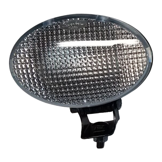
Light Kit
Power Max
Model No. 107-3827
Save these instructions with your Operator's Manual for
future reference.
Contents of the Kit
DESCRIPTION
Headlamp
Wire harness
U-clamp
Bracket
Washers
Nut, 5/16 in.
Locknuts, 1/4 in.
Serrated flange locknut
Plastic cable tie
Installing the Light Kit
1. Secure the ring terminal of the wire harness to the
right rear engine mounting bolt with a serrated flange
locknut provided in the kit (Fig. 1).
5
6
Figure 1
1. Right rear engine
mounting bolt
2. Serrated flange locknut
3. Ring terminal
2003—The Toro Company
8111 Lyndale Ave., Bloomington, MN 55420, USA
Snowthrowers with Alternator
QUANTITY
1
1
1
1
2
1
2
1
1
4
1
2
3
4. Alternator connector
5. Wire harness connector
6. Wire harness
Printed in the USA
All Rights Reserved
Installation Instructions
Note: Position the ring terminal so that the wire
harness is routed toward the rear of the snowthrower
(Fig. 1).
2. Remove the rubber boot from the alternator connector
that hangs over the electric starter (Fig. 1).
3. Securely connect the wire harness connector to the
alternator connector (Fig. 1).
4. Secure the wire harness to the lower right side of the
handle assembly with a plastic cable tie (provided in
the kit) about an inch (2.5 cm) below the bottom end
of the upper handle (Fig. 2).
1
3
Figure 2
1. Upper handle
2. Wire harness
Form No. 3351-124
2
3. Plastic cable tie
Original Instructions (GB)
Advertisement

Related Manuals for Toro Power Max 107-3827


Summary of Contents for Toro Power Max 107-3827
- Page 1 1. Right rear engine 4. Alternator connector mounting bolt 5. Wire harness connector 2. Serrated flange locknut 6. Wire harness 3. Ring terminal 2003—The Toro Company Printed in the USA Original Instructions (GB) 8111 Lyndale Ave., Bloomington, MN 55420, USA All Rights Reserved...
- Page 2 5. Secure the bracket to the right side of the handle using the U-clamp, 2 washers, and 2 locknuts (1/4 in.) provided in the kit (Fig. 3). Figure 3 1. Headlamp 5. Handle 2. Bracket 6. U-bolt 3. Nut (5/16 In.) 7.
-
Page 3: Inhalt Des Kits
2. Nehmen Sie den Gummischuh vom Lichtmaschinen- anschluss ab, der über dem Elektrostart hängt (Bild 1). 3. Befestigen Sie den Kabelbaumanschluss am Lichtmaschinenanschluss (Bild 1). 2003 – The Toro Company Druck: USA Übersetzung des Originals (D) 8111 Lyndale Ave., Bloomington, MN 55420, USA... - Page 4 4. Befestigen Sie den Kabelbaumanschluss mit einer Kunststoffkabelbinde (aus dem Kit) unten rechts am Griff, ungefähr 2,5 cm unter dem unteren Ende des oberen Griffs (Bild 2). Bild 3 Bild 2 1. Scheinwerfer 5. Griff 1. Oberer Griff 3. Kunststoffkabelbinde 2.
- Page 5 électrique (Fig. 1). 3. Fixez solidement le connecteur du faisceau de câblage au connecteur de l’alternateur (Fig. 1). 2003 – The Toro Company Imprimé aux États-Unis Traduction de l’original (F) 8111 Lyndale Ave., Bloomington, MN 55420, États-Unis...
- Page 6 4. Fixez le faisceau de câblage au côté inférieur droit de l’ensemble guidon avec un serre-câble en plastique (fourni avec le kit) à environ 2,5 cm au-dessous de l’extrémité inférieure de la partie supérieure du guidon (Fig. 2). Figure 3 Figure 2 1.
-
Page 7: Contenuto Del Kit
(Fig. 1). 3. Collegate saldamente il connettore del cablaggio preassemblato al connettore dell’alternatore (Fig. 1). 2003 – The Toro Company Stampato negli USA Traduzione del testo originale (I) 8111 Lyndale Ave., Bloomington, MN 55420, USA... - Page 8 4. Fissate il cablaggio preassemblato sul lato destro del gruppo stegola, in basso, con una fascetta in plastica per cavi (a corredo), circa 2,5 cm. sotto l’estremità inferiore della stegola superiore (Fig. 2). Figura 2 Figura 3 1. Stegola superiore 3.
- Page 9 3. Ringkobling 6. Ledningsfastspenner Obs: Plasser ringkoblingen slik at ledningsfast- spenneren ledes mot baksiden av snøfreseren (fig. 1). 2003 – The Toro Company Trykt i USA Oversettelse av originalen (N) 8111 Lyndale Ave., Bloomington, MN 55420, USA Med enerett...
- Page 10 5. Fest braketten til høyre side av håndtaket ved hjelp av U-klemmen, to skiver og to låsemutre (1/4 tomme) som medfølger i settet (fig. 3). Figur 3 1. Frontlys 5. Håndtak 2. Brakett 6. U-bolt 3. Mutter (5/16 tomme) 7. Kabelsnor i plast 4.
-
Page 11: Satsens Innehåll
5. Ledningsnätanslutning 3. Ringkoppling 6. Ledningsnät Observera: Placera ringkopplingen så att ledningsnätet är draget mot snöslungans bakre del (fig. 1). Översättning av originalet (S) 2003 – The Toro Company Tryckt i USA 8111 Lyndale Ave., Bloomington, MN 55420, USA Med ensamrätt... - Page 12 5. Montera fästet på handtagets högra sida med U-klämman, två brickor och två låsmuttrar (1/4”) som medföljer i satsen (fig. 3). Figur 3 1. Strålkastare 5. Handtag 2. Fäste 6. U-bult 3. Mutter (5/16”) 7. Kabelband i plast 4. Ledningsnät 8.
- Page 13 2. Hammastettu 5. Johdinsarjan liitin laippalukkomutteri 6. Johdinsarja Huomautus: Sijoita rengasliitin siten, että johdinsarja kulkee lumilingon takaosaan päin (kuva 1). 2003 – The Toro Company Painettu Yhdysvalloissa Käännös alkutekstistä (SF) 8111 Lyndale Ave., Bloomington, MN 55420, USA Kaikki oikeudet pidätetään...
- Page 14 5. Kiinnitä kannatin kahvan oikealle puolelle U-liittimellä, kahdella aluslevyllä ja kahdella 1/4 tuuman lukkomutterilla (pakkauksessa) (kuva 3). Kuva 3 1. Ajovalo 5. Kahva 2. Kannatin 6. U-pultti 3. Mutteri (5/16 tuumaa) 7. Muovinen nippuside 4. Johdinsarja 8. Lukkomutterit, 1/4” 6. Kiinnitä ajovalo kannattimeen (kuva 3) mukana toimitetulla 5/16 tuuman mutterilla.