Table of Contents
Advertisement
Quick Links
Advertisement
Table of Contents

Related Manuals for Datex-Ohmeda Avance


Summary of Contents for Datex-Ohmeda Avance
- Page 1 Avance User’s Reference Manual Software Revision 8.X...
- Page 2 Datex-Ohmeda, Inc., a General Electric Company, doing business as GE Healthcare. User Responsibility This Product will perform in conformity with the description thereof contained in this User’s Reference manual and accompanying labels and/or inserts, when assembled, operated, maintained, and repaired in accordance with the instructions provided.
-
Page 3: Table Of Contents
Table of Contents 1 Introduction Intended use ........1-2 Symbols used in the manual or on the equipment . - Page 4 Avance Using the ComWheel ......2-13 Using quick keys ......2-13 Using Select Page menu .
- Page 5 Table of Contents Setting apnea time ......3-22 Viewing alarm history ......3-22 Spirometry .
- Page 6 Avance System ........5-8 Circuit .
- Page 7 Maintenance summary and schedule ....9-4 Datex-Ohmeda approved service ....9-4...
- Page 8 Avance Circuit O2 cell replacement ......9-6 Calibration menu ....... . . 9-7 Flow and pressure calibration .
- Page 9 Table of Contents Battery information ......11-9 Flow specifications ....... 11-9 Breathing system specifications .
- Page 10 Avance Setting graphical trends pages ....12-4 Display settings ....... . . 12-6 Setting colors and units .
-
Page 11: Introduction
1 Introduction In this section Intended use ........1-2 Symbols used in the manual or on the equipment . -
Page 12: Intended Use
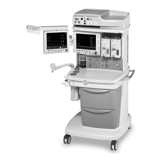
Optional, integrated features include auxiliary O2 and suction control. The Avance system offers improved usability through integration of ventilation, gas delivery and gas monitoring (E and M-Series respiratory gas module capable) on a full-color 12-inch display. - Page 13 1 Introduction Note Configurations available for this product depend on local market and standards requirements. Illustrations in this manual may not represent all configurations of the product. This manual does not cover the operation of every accessory. Refer to the accessory documentation for further information.
-
Page 14: Symbols Used In The Manual Or On The Equipment
Avance Symbols used in the manual or on the equipment Symbols replace words on the equipment, on the display, or in Datex-Ohmeda manuals. Warnings and Cautions tell you about dangerous conditions that can occur if you do not follow all instructions in this manual. - Page 15 1 Introduction Serial number Stock number Equipotential Lamp, lighting, illumination Variability Variability in steps Suction bottle outlet Vacuum inlet Maximum Vacuum Exhaust Bellows volumes are approximate Plus, positive polarity Minus, negative polarity Bag position/manual ventilation Mechanical ventilation Inspiratory flow Expiratory flow Movement in one direction Movement in two directions Lock...
- Page 16 EEC) for Medical Devices when they are used as specified in their User’s Reference manuals. The xxxx is the certification number of the Notified Body used by Datex-Ohmeda’s Quality Systems. Date of manufacture Manufacturer Indicates that the waste of electrical...
- Page 17 1 Introduction Alarm silence touch key (Tec 6 Plus) When moving or transporting anesthesia machine, place the display arm in the transport position as shown. Maximum mass of configured mobile equipment M1204616...
-
Page 18: Typeface Conventions Used
Avance Typeface conventions used Names of hard keys on the display and modules are written in bold Normal Screen typeface; for example, Menu items are written in bold italic typeface; for example, Vent Setup. Messages that are displayed on the screen are enclosed in single quotes;... -
Page 19: Abbreviations
1 Introduction Abbreviations Abbreviation Definition Anesthetic agent Advanced breathing system ACGO Auxiliary Common Gas Outlet AGSS Anesthesia Gas Scavenging System Alt O2 Alternate O2 Adjustable pressure-limiting Apnea Common Gas Outlet Carbon dioxide Compl Compliance CPAP/PSV Constant Positive Airway Pressure/Pressure Support Ventilation End-tidal concentration EtCO2... - Page 20 Avance Abbreviation Definition Oxygen Pair Air supply pressure Paux Auxiliary pressure Airway pressure Pressure controlled ventilation PCV-VG Pressure controlled ventilation - volume guaranteed PEEP Positive end expiratory pressure PEEPe Extrinsic positive end expiratory pressure Pexp Expiratory pressure Pressure-flow loop Pinsp...
-
Page 21: System Information
1 Introduction System information System classification This system is classified as follows. • Class I Equipment. • Type B Equipment. • Type BF Equipment. • Ordinary Equipment. • Not for use with flammable anesthetics. • Continuous operation. Device standards Devices used with this anesthesia system shall comply with the following standards where applicable: •... -
Page 22: System Safety
Avance System safety Preparing for use WARNING Read each component’s User’s Reference manual and understand the following before using this system: • All system connections. • All warnings and cautions. • How to use each system component. • How to test each system component. -
Page 23: Inspecting The System
1 Introduction Be aware of the risks and precautionary measures related to phthalates. The following types of procedures may increase the risk of exposure to phthalates when a device containing phthalates is used for the treatment of children or treatment of pregnant or nursing women: •... -
Page 24: Electrical Safety
Avance • The necessary emergency equipment is available and in good condition. • Equipment for airway maintenance, manual ventilation, tracheal intubation, and IV administration is available and in good condition. • Applicable anesthetic and emergency drugs are available. • The casters are not loose and the brakes are set and prevent movement. - Page 25 1 Introduction An operator of the medical electrical system must not touch non-medical electrical equipment and the patient simultaneously. This may cause an unsafe electrical shock to the patient. Use of portable phones or other radio frequency (RF) emitting equipment (that exceed electromagnetic interference levels specified in IEC 60601-1-2) near the system may cause unexpected or adverse operation.
- Page 26 Avance 1-16 M1204616...
-
Page 27: System Controls And Menus
2 System controls and menus In this section System overview........2-2 Advanced breathing system components . -
Page 28: System Overview
Avance System overview 1. Light switch 7. Integrated suction (optional) 2. Dovetail 8. Brake 3. Vaporizer 9. O2 flush button 4. Alternate O2 control 10. Advanced breathing system 5. System switch 11. Auxiliary O2 flow control (optional) 6. Mains indicator 12. - Page 29 2 System controls and menus 1. Outlet circuit breaker 7. AGSS (Anesthesia Gas Scavenging System) 2. Isolated electrical outlet (optional) 8. Equipotential stud 3. Cable access door 9. Mains inlet 4. Vacuum connection 10. System circuit breaker 5. Collection bottle connection 11.
-
Page 30: Using The Brakes
Avance Using the brakes Brakes on the casters hold the system in place. 1. Push down on the brake to lock the casters. 2. Lift up on the brake to release the brake. The casters are unlocked. Using the O2 flush The O2 flush button supplies a high flow of O2 to the breathing system. -
Page 31: Advanced Breathing System Components
2 System controls and menus Advanced breathing system components 1. Expiratory check valve 9. Manual bag port 2. Inspiratory check valve 10. Adjustable pressure-limiting (APL) valve 3. Inspiratory flow sensor 11. Bag/Vent switch 4. Expiratory flow sensor 12. Bellows assembly 5. -
Page 32: Using The Bag Support Arm
Avance 1. Bag support arm 2. Auxiliary Common Gas outlet (ACGO) switch 3. ACGO port 4. EZchange canister module (CO2 bypass) 5. EZchange canister release 6. Condenser drain button 7. Condenser Figure 2-4 • Breathing system options Using the bag Use the optional bag support arm to hold the breathing circuit bag. -
Page 33: Vaporizer Controls
2 System controls and menus Vaporizer controls Refer to the vaporizer User’s Reference manual for more detailed information on the vaporizer. 1. Lock lever 2. Concentration control and release 3. Indicators 4. Silence alarm touch key Figure 2-5 • Vaporizer controls M1204616... -
Page 34: Display Controls
Avance Display controls Silence Alarms key Silences any active, silenceable high and medium priority alarms or to suspend/ acknowledge any non-active medium or high priority alarms. Alarm is silenced for 120 seconds or alarm is suspended for 90 seconds. Menu keys Shows corresponding menu. -
Page 35: Menu Keys
2 System controls and menus Menu Keys 1. Alarms Setup 2. Help 3. Trends 4. Main Menu 5. Checkout 6. Start/End Case 7. Spirometry 8. Vent Setup 9. Gas Setup 10. Procedures Figure 2-7 • Menu keys M1204616... -
Page 36: Anesthesia System Display
Avance Anesthesia system display Plug in power Timer: cable. On battery. cmH2O Measured Ppeak Pmean l/min PEEP RR /min Fi % Et % Agent MAC 40 EtCO2 %s FiCO2 %s EtO2 % FiO2 % Fresh Gas: O2+Air PCV-VG: Ventilator On... -
Page 37: Waveform Fields
2 System controls and menus Waveform fields Up to three waveforms can be shown on the normal screen view. Each waveform can be set to show specific information such as Paw, agent, flow, or CO2 data. The corresponding numeric information shows in the measured values field to the right of the waveform. -
Page 38: Display Navigation
Avance Display navigation Use the menus, ComWheel, quick keys, and Select Page menu to navigate the display. cmH2O Main Menu Ppeak Pmean Trends System Status PEEP RR /min Cardiac Bypass Fresh Gas Usage Screen Setup Fi % Et % Parameters Setup... -
Page 39: Using Menus
2 System controls and menus Using menus Use the menu keys to access the corresponding menus. Use the ComWheel to navigate the menus. When a menu key is selected, the menu field overlays the normal view and the waveform fields start at the right edge of the menu. -
Page 40: Using Select
Avance Using Select Page Use the Select Page menu to switch the normal screen view. A menu default screen view (case type) and four preset normal screen views are available. See the “Super user mode” section for information on setting the normal screen views. - Page 41 3 Operation In this section System operation safety ......3-2 Turning on the system ......3-4 Start a case.
-
Page 42: System Operation Safety
Avance System operation safety WARNING Do not use antistatic or electrically-conductive breathing tubes or masks. They can cause burns if used near high- frequency surgical equipment. Explosion Hazard. Do not use this system with flammable anesthetic agents. Ventilator alarms indicate potential hazard conditions. - Page 43 3 Operation Unplug the system power cord to run the system on the battery power if the integrity of the protective earth conductor is in doubt. The top shelf weight limit is 34 kg (75 lb). Do not subject the system to excessive shock and vibration.
-
Page 44: Turning On The System
Avance Turning on the system 1. Plug the power cord into an electrical outlet. Make sure the system circuit breaker is on. • The mains indicator is lit when AC power is connected. • Battery is charging if it is not already fully charged. -
Page 45: Start A Case
3 Operation Start a case Use the Start Case menu to set up the case and to start the gas flow. A case can be started using default settings or using custom settings. The default settings are configured by the Super User. See the “Super user mode”... -
Page 46: Minimum Alveolar Concentration
Avance Minimum Alveolar The adjusted Minimum Alveolar Concentration (MAC) is calculated Concentration based on the patient age entered in the Start Case menu. The default patient age of selected case type is used if no patient age is entered. The MAC value is calculated from the exhaled gas concentration and the related affects based on the age of the patient. - Page 47 3 Operation 4. To change ventilation settings or the ventilation mode, push the Vent Setup key. Make the change. Alarms Setup 5. To change alarm settings, push the key. Make the change. 6. To change the gas settings or the circuit type, push the Setup key.
-
Page 48: End A Case
Avance End a case Use the End Case menu to stop gas flow and end the patient alarms. End Case End Case Now Normal Screen 1. Set the Bag/Vent switch to Bag. Start/End Case 2. Push the key. 3. Select End Case Now to put the system in standby (stops gas flow and patient alarms). -
Page 49: Ventilator Setup
3 Operation Ventilator setup Use the Vent Setup menu to set the ventilation mode and ventilator settings. WARNING Most anesthetic agents will cause patients to have reduced ventilatory responses to carbon dioxide and to hypoxemia. Therefore, triggered modes of ventilation may not produce adequate ventilation. - Page 50 Avance 2. Select the desired mode and push the ComWheel to enter the adjustment window for that mode. 3. Use the ComWheel to navigate the adjustment window and to change a value. 4. Select Confirm to activate the mode. 3-10...
-
Page 51: Gas Setup
3 Operation Gas setup Use the Gas Setup menu to adjust the O2% and total flow, to change the balance gas, and to change the circuit type. Gas Setup Adjust Settings Gas: Circuit: Circle Non-Circle Normal Screen Changing gas Gas Setup 1. -
Page 52: Using The Circle Circuit
Avance 2. Select Circle or Non-Circle and push the ComWheel to enter the adjustment window. 3. Confirm or change and confirm the settings. Using the circle Use the circle circuit mode to combine fresh gas with recirculated gas circuit from the CO2 absorber. The combined gas flows out through the inspiratory port. - Page 53 3 Operation Note The fresh gas oxygen concentration may not reflect FiO2 when using these types of circuits. Use an external O2 monitor when using a rebreathing circuit with the non-circle circuit. 3-13 M1204616...
-
Page 54: Main Menu
Avance Main Menu Use the Main Menu to access menus and settings for Trends, System Status, Cardiac Bypass, Fresh Gas Usage, Screen Setup, Parameters Setup, Calibration, and Super User. Note System Status shows the status of gas supplies, electrical supplies, and software settings. -
Page 55: Fresh Gas Usage
3 Operation Using manual ventilation 1. Set the Bag/Vent switch to Bag. cardiac bypass Main Menu 2. Push the key. 3. Set Cardiac Bypass to On. The general message ‘Cardiac Bypass’ shows in the waveforms and in the general message field when manual ventilation cardiac bypass is active. - Page 56 Avance Screen Setup Waveform Field 1 Paw Waveform Field 2 Flow Waveform Field 3 CO2 Digit Field AA Fresh Gas Controls O2% Split Screen None Sweep Speed Fast Brightness 4 Time and Date Previous Menu Setting waveform fields The waveforms can be set to show agent, CO2, flow, Paw, or set to off.
- Page 57 3 Operation 3. Select O2% or Flow. When set to O2%, balance gas adjusts automatically when either the O2% or the total flow is changed using the gas quick keys. When set to Flow, balance gas and the O2% are controlled individually using the gas quick keys.
- Page 58 Avance Time and Date Hour Minutes Zero Seconds Month Year Clock Format 24 h Previous Menu Main Menu 1. Push the key. 2. Select Screen Setup -Time and Date. 3. Select the item to change. Make the change. The clock format factory default is 24 hours.
-
Page 59: Trends
3 Operation Trends Use the Trends menu to view patient trends and set the time scale. There are three views for patient trends: measured (numerical), settings, and graphical. Trend information is saved every 1 minute for the most recent 24 hours. Trends Cursor Next Page... -
Page 60: Alarm Setup
Avance Alarm setup Use the Alarm Setup menu to set and adjust alarm limits, alarm volume, and other alarm settings and to view alarm history. Setting Leak Audio to Off silences audio alarms for small leaks. Leak Audio is automatically set to On and cannot be changed when either the Low MV alarm limits are off or the MV/TV Alarms is set to Off. -
Page 61: Setting Mv/Tv Alarms
3 Operation • If mechanical ventilation is started, the volume apnea alarms are active. • If manual ventilation is restarted, a pop-up confirmation window appears to resume the Off setting. 3. To turn the volume apnea alarms on, select Volume Apnea and set to On. -
Page 62: Setting Auto Mv Limit
Avance 2. To turn off the CO2 alarms, select CO2 Alarms and set to Off. The ‘CO2 Alarms Off’ message shows in the general message field. The CO2 alarm limit waveform numerics show as dashes during a case. The alarms remain disabled until the Bag/Vent switch is set to ventilator, the case is ended, or the CO2 Alarms is set to On. - Page 63 3 Operation 2. Select Alarm History. The list of alarms show in the window. Back is selected by default. 3. Push the ComWheel to return to the Alarm Setup menu. Normal Screen 4. Push the key or select Previous Menu. 3-23 M1204616...
-
Page 64: Spirometry
Avance Spirometry Use the Spirometry menu to: • Set the loop type. • Adjust the loop scaling. • Access the Spirometry Setup menu. • Save a loop to memory. • View a saved loop. • Erase a saved loop. There are three types of spirometry loops: Pressure-Volume (P-V), Flow-Volume (F-V) and Pressure-Flow (P-F). -
Page 65: Setting Loop Type
3 Operation Spirometry Loop Type Scaling Spiro Setup Save Loop Reference Loop None Erase Loop None Previous Menu Setting loop type Spirometry 1. Push the key. 2. Select Loop Type and set the loop type. • Set to P-F for Paw-Flow. •... -
Page 66: Spirometry Setup
Avance 2. Select Scaling. 3. Set the scale type to AUTO, Linked, or Indep. Normal Screen 4. Push the key or select Previous Menu. Spirometry setup Use the Spirometry Setup menu to: • Set the patient and sensor type. •... -
Page 67: Storing, Viewing, Erasing Spirometry Loops
3 Operation When the airway module is selected as the data source, make sure that a D-lite or Pedi-lite sensor is properly connected on the airway module. If the sensor is not properly connected, the waveform shows no flow and the gas monitor samples room air. Spirometry 1. -
Page 68: Procedures
Avance Procedures Use the Procedures menu to pause the gas flow, perform or change the settings for a vital capacity procedure, or perform or change the settings for a cycling procedure. Note Vital Capacity shows in the menu if it is set to Yes in the Super User menu. -
Page 69: Vital Capacity
3 Operation Vital capacity Use the Vital Capacity procedure to deliver a pressure breath for a set time. The Vital Capacity procedure provides a simple way to delivery one pressure breath during mechanical ventilation without making multiple ventilator setting changes. The PEEP on Exit setting provides a way to change the ventilation PEEP setting automatically at the end of the Vital Capacity procedure. -
Page 70: Cycling
Avance Cycling Use the Cycling procedure to delivery pressure breaths through a series of ventilation steps. The Cycling procedure provides a flexible way to deliver pressure breaths during ventilation without making multiple ventilator setting changes. Up to seven preset steps with multiple breaths are available. - Page 71 3 Operation 8. When finished changing settings, select Confirm. Adjust Settings is selected by default. 9. Perform a procedure if desired. Normal Screen 10. Push the key or select Previous Menu. 3-31 M1204616...
-
Page 72: Alternate O2 Control
Avance Alternate O2 control WARNING The Alternate O2 control is not an auxiliary source of O2. When Alternate O2 control is enabled, flow from the electronic mixer is stopped. O2 is flowing through the Alternate O2 control to the breathing system. To activate anesthetic agent flow to the breathing system, set the agent to the desired concentration. -
Page 73: Ezchange Canister Mode
3 Operation EZchange canister mode Use the optional EZchange canister mode for continued ventilation of the patient while changing the absorber canister. The EZchange canister mode seals the breathing circuit when the canister holder is down. While the absorber canister is out of the breathing circuit, the patient re-breaths exhaled gases without any gas passing through the absorbent. - Page 74 Avance 3. Install a canister with fresh absorbent into the holder. 4. Push the canister back up and snap it into absorber position. The exhaled gas flows through the absorber, removing CO2. Note Make sure that the absorber canister has side rails. If the canister does not have side rails, it will not work in the EZchange canister holder.
-
Page 75: Condenser
3 Operation Condenser Use the optional condenser to remove water in the system that is produced from the reaction of CO2 gas with the absorbent. The condenser is connected between the outlet of the absorber canister and the inlet of the circuit module. Moisture in the gas is condensed into water droplets, which run into the condenser’s reservoir. -
Page 76: Auxiliary Common Gas Outlet
Avance Auxiliary Common Gas Outlet Use the optional Auxiliary Common Gas Outlet (ACGO) switch to direct the fresh gas flow through the ACGO port on the front of the system. The ACGO may be used to provide fresh gas to an auxiliary manual breathing circuit. -
Page 77: Preoperative Checkout
4 Preoperative checkout In this section Every day before your first patient ....4-2 Before every patient ....... 4-3 M1204616... -
Page 78: Every Day Before Your First Patient
Avance Every day before your first patient Check that necessary emergency equipment is available and in good condition. Check that the equipment is not damaged and that components are correctly attached. Check that pipeline gas supplies are connected and cylinders are installed. -
Page 79: Before Every Patient
4 Preoperative checkout Before every patient Note This check does not need to be done before the first case of the day if the “Every day before your first patient” checklist was done. Check that necessary emergency equipment is available and in good condition. - Page 80 Avance M1204616...
-
Page 81: Preoperative Tests
5 Preoperative tests In this section Vaporizer installation ......5-2 Flow and pressure calibration ......5-3 Circuit compliance compensation . -
Page 82: Vaporizer Installation
Avance Vaporizer installation WARNING Use only the Datex-Ohmeda Selectatec series vaporizers Tec 4 or greater. Do not use a vaporizer that lifts off of the manifold when the lock lever is in the locked position. Do not use this anesthesia system if more than one vaporizer can be turned on at the same time. -
Page 83: Flow And Pressure Calibration
5 Preoperative tests Flow and pressure calibration Calibrate the flow sensors by removing them from the system. On- Main Menu screen instructions are available through - Calibration - Flow and Pressure. Important Room temperature fluctuations of more than 5°C may affect sensor measurements. -
Page 84: Circuit Compliance Compensation
Avance Circuit compliance compensation The ventilator adjusts gas delivery and monitoring to compensate for the compliance of the patient circuit if: • The system has a gas analyzer installed. • The Circuit Compliance is set to On in the Super User - Ventilator Settings menu. -
Page 85: Checkout Menu
5 Preoperative tests Checkout menu The Checkout menu shows on the display after turning on the system. To access the Checkout menu between cases, push the Checkout key. Step-by-step instructions show in the right window next to the Checkout menu during the checks. Use the Checkout menu to: •... -
Page 86: Machine Check
Avance Machine check The Machine Check or the individual checks must be performed at least once within every 24-hour period. Perform the Machine Check at the start of each day. The machine check runs automatically and beeps to indicate when it is finished or if interaction is required. -
Page 87: Machine Check - Circuit O2
5 Preoperative tests 4. (ACGO option only.) Set the ACGO switch to Circle. 5. Select Start. The display shows the checks being run. • The system beeps when the check is done. • The results are shown on the display. 6. -
Page 88: Individual Checks
Avance Individual checks The Machine Check or the individual checks must be performed at least once within every 24-hour period. Individual checks allow the user to perform any combination of single checks. These checks are helpful if there is a specific problem/alarm and the user wishes to test only that portion of the system. -
Page 89: Circuit O2 Cell
5 Preoperative tests Circuit O2 cell The Circuit O2 Cell check measures the O2%. 1. Open the patient Y. 2. Set the Bag/Vent switch to Vent. 3. (ACGO option only.) Set the ACGO switch to Circle. 4. The display will show the O2%. Do not select Done when 21 is first displayed. -
Page 90: Positive Low Pressure Leak Test (Acgo Systems Only)
Avance Positive low pressure leak test (ACGO systems only) Note For ACGO machines, perform either a negative Low P Leak check in the Checkout menu or positive low-pressure leak check depending on local requirements. CAUTION Do a positive-pressure leak test at the ACGO port only. -
Page 91: Vaporizer Back Pressure Test
5 Preoperative tests Vaporizer back pressure test WARNING Anesthetic agent comes out of the circuit during this test. Use a safe, approved procedure to collect and remove the agent. 1. Set the System switch to On. 2. Start a case. 3. - Page 92 Avance 5-12 M1204616...
-
Page 93: Airway Modules
6 Airway modules In this section Airway modules ........6-2 Parameters setup . -
Page 94: Airway Modules
Avance Airway modules The optional compact airway modules measure and monitor gases delivered to the patient and exhaled through the breathing circuit. The modules consist of an infrared sensor for measuring CO2, N2O, and anesthetic agents; a paramagnetic O2 sensor; and a gas sampling system with the D-fend water separation system. - Page 95 6 Airway modules Use only airway modules that have anesthetic agent monitoring and O2 monitoring on this system. The following modules can be used on this system: E-CAiO, E-CAiOV, E-CAiOVX, M-CAiO, M-CAiOV, and M-CAiOVX. (E series modules must be software version 4.5 and above.
-
Page 96: Connection To A Patient
Avance Connection to a 1. Check that the airway gas module is installed. patient 2. Check that the airway adapter connections are tight and that the adapter is correctly installed. 3. Check that the water trap container is empty and properly attached. -
Page 97: Parameters Setup
6 Airway modules Parameters setup Use the Parameters Setup menu to change the monitoring settings Main of the data source, CO2, O2, agent, and spirometry. Push the Menu key. Select Parameters Setup. Data source Several monitoring parameters can be obtained from the ventilator or the airway module. -
Page 98: Automatic Agent Identification
Avance Automatic agent identification Airway modules with agent identification will automatically identify and select Halothane, Enflurane, Isoflurane, Sevoflurane, and Desflurane. The inspiratory and expiratory concentrations of the agent appear in the number field or the agent waveform field if selected. -
Page 99: Calibration
6 Airway modules Calibration Calibrate airway modules once every six months or whenever there are indications of errors in the gas readings. Use a Datex-Ohmeda calibration gas and regulator to calibrate the modules. See the “Parts” section for the stock numbers of the calibration gas and regulator. - Page 100 Avance 10. If adjustments are needed: • Do not close the regulator until all the adjustments have been made. • Select the gas to be adjusted and press the ComWheel. • Use the ComWheel to change the value until it matches the calibration gas cylinder value.
-
Page 101: Alarms And Troubleshooting
7 Alarms and troubleshooting CAUTION No repair should ever be attempted by anyone not having experience in the repair of devices of this nature. See the “Repair policy” in the “User maintenance” section. WARNING If an alarm occurs, safeguard the patient first before performing troubleshooting or doing repair procedures. -
Page 102: Alarms
Avance Alarms Alarms are divided into technical alarms and parameter alarms. These alarms may be high priority, medium priority, or informational. When an alarm occurs during a case, an alarm tone sounds and the alarm message is displayed in the alarm message field. The alarm tone is approximately 52 to 70 db(A). -
Page 103: Display Changes During Alarms
5 minutes of battery power remaining. Red indicates less than 5 minutes battery power remaining. Internal failure ‘Internal problem prevents normal operation.’ shows on the display during a software or hardware failure that requires service. If this message occurs, contact a Datex-Ohmeda trained service representative. M1204616... -
Page 104: List Of Alarms
Air pipeline pressure is less than Ensure the air pipeline and cylinder are pressure low 252 kPa (36 psi) and the air properly connected. cylinder pressure dropped below Contact a Datex-Ohmeda trained service 2633 kPa (381 psi) for one representative. second. Apnea Medium Apnea time delay (10-30 Check for leaks in the patient circuit. - Page 105 Start a new case. sensors Cannot monitor Medium Air pipeline pressure is invalid. Check pipeline supply pressure. Air pipeline Contact a Datex-Ohmeda trained service representative. Cannot monitor Informational Hardware failure. Contact a Datex-Ohmeda trained service gas supplies representative.
- Page 106 Avance Message Priority Cause Action Display panel Medium Communication lost between Turn the system off and back on. controls failure panel and key pad. EtCO2 high High EtCO2 is greater than high alarm Check the patient and EtCO2 settings. Check limit.
- Page 107 Inspiration Medium High airway pressure. Check system for blockages. stopped Internal failure. High Power controller software failure. Contact a Datex-Ohmeda trained service System may representative. shut down. Internal failure. Medium Power controller software failure. Contact a Datex-Ohmeda trained service System may representative.
- Page 108 Avance Message Priority Cause Action Memory Informational Software error. Contact a Datex-Ohmeda trained service (EEPROM) representative. failure Module fail. No Medium Airway module hardware failure. Replace module. CO2, AA, O2 data. Module not Informational The monitoring module detected Remove the incompatible module. Use a...
- Page 109 Airway module sample line is Replace airway module sample line. blocked blocked. Service Informational Calibration data is corrupt. Contact a Datex-Ohmeda trained service calibration representative. advised Set Alt O2 flow! Medium Software or hardware failure Contact a Datex-Ohmeda trained service Check agent prevents mixed gas delivery.
- Page 110 Using battery. Medium Mains supply is OK, but the Shut down the system as soon as possible. Power system is running on the battery. Contact a Datex-Ohmeda trained service Controller fail. representative. Ventilate High Software or hardware failure Use a manual bag to ventilate the patient or manually! prevents mechanical ventilation.
- Page 111 Shut down PSV. Informational priority alarm when system as soon as possible. Contact a Bag/Vent switch is in Vent and Datex-Ohmeda trained service not running PCV, PSVPro, SIMV- representative. PC, CPAP/PSV, PCV-VG mode; Bag/Vent switch is in Bag; or Non-circle circuit or ACGO is selected.
-
Page 112: Alarm Ranges
Avance Alarm ranges The alarms names are listed in order they appear on the Alarm Limits page accessible from the Alarm Setup menu. See the “Super user mode” section for more information on the alarm default settings. Alarm Range Increment... - Page 113 7 Alarms and troubleshooting Alarm Range Increment EtSEV Low Off, 0.1 - 9.9% 0.1% EtDES High 0.1 - 20%, Off 0.1% EtDES Low Off, 0.1 - 19.9% 0.1% EtENF High 0.1 - 7.0%, Off 0.1% EtENF Low Off, 0.1 - 6.9% 0.1% EtHAL High 0.1 - 7.0%, Off...
-
Page 114: Alarm Tests
Avance Alarm tests Test the system to verify that alarms are functioning. Note If an airway module is installed, the FiO2 readings are taken from the module instead of from the O2 cell. A sample line must be connected from the airway module to the breathing circuit in order to test the O2 alarms. - Page 115 7 Alarms and troubleshooting 9. Test the Ppeak low. Leak? alarm: • Unblock the patient connection. • Set the Bag/Vent switch to Vent. • Set the tidal volume and total flow to minimum. • Other alarms such as MVexp low can occur. •...
-
Page 116: Breathing System Problems
Breathing System Cleaning and Sterilization” User’s Reference manual. The bellows fills when the Bag/ Leak through Bag/Vent switch. Contact a Datex-Ohmeda trained service Vent switch is set to Bag or the representative to repair the system. bag fills when the switch is set to Vent. -
Page 117: Electrical Problems
7 Alarms and troubleshooting Electrical problems WARNING If a circuit breaker opens frequently, do not use the system. Have a Datex-Ohmeda trained service representative repair the system. Symptom Problem Solution Mains indicator is not on. The electrical power cable is not Connect the power cable. -
Page 118: Pneumatic Problems
A vaporizer malfunction (the leak Send the vaporizer to a stops if you use a different Datex-Ohmeda Service Center for vaporizer in the same position). repair. A port valve malfunction (the leak Contact a Datex-Ohmeda trained... -
Page 119: Setup And Connections
8 Setup and connections In this section Setup safety ........8-2 Setting up the absorber canister . -
Page 120: Setup Safety
Avance Setup safety WARNING Datex-Ohmeda strongly recommends the use of O2 monitoring and anesthetic agent monitoring with this equipment. Failure to use monitoring could result in injury to the patient. Refer to local standards for mandatory monitoring. Always make sure that the pipeline supply hoses and the breathing circuit components are not toxic and will not: •... - Page 121 8 Setup and connections Use only reservoir bags that comply with EN1820 on this system. Use only breathing tubes that comply with EN12342 on this system. A malfunction of the medical gas central supply system may cause all connected devices to stop. Always connect the expiratory flow sensor.
-
Page 122: Setting Up The Absorber Canister
Avance Setting up the absorber canister The absorber canister is available in two versions: Disposable Multi Absorber and Reusable Multi Absorber. Both are removed and installed on the breathing system in the same way. Each canister holds 800 grams of loose absorbent. The manufacturer recommends MedisorbTM absorbent. -
Page 123: When To Change The Absorbent
8 Setup and connections WARNING Obey applicable safety precautions: • Do not use the absorber with chloroform or trichloroethylene. • The Disposable Multi Absorber is a sealed unit which should not be opened or refilled. • Avoid skin or eye contact with the contents of the absorber. -
Page 124: Removing A Canister
Avance Removing a canister 1. Hold the canister by the handle and push on the release latch to unlock the canister. 2. Remove the canister by tilting it downward and off the two support pins. Removing an 1. Hold the canister by the handle and push the canister cradle release latch to unlock the canister cradle. -
Page 125: Filling The Reusable Multi Absorber Canister
8 Setup and connections Filling the Reusable 1. Turn the canister upside down and, using your thumbs, turn the Multi Absorber cover locking ring counterclockwise to unlock it. canister 2. Push up to release the seal. 3. Lift off the cover to remove it. 4. - Page 126 Avance 6. Place a new filter in the bottom of the canister, pour absorbent into the canister and place a new filter over the absorbent before closing and locking the cover. Wipe off any absorbent dust. 7. Align the cover slots with the canister locking tabs and press the cover down into place.
-
Page 127: Electrical Connections
8 Setup and connections Electrical connections Mains inlet Arrow shows the mains power inlet and cord. Outlets Labels show outlet voltage ratings and circuit breaker amp ratings. These are isolated outlets. Regularly test the leakage current. M1204616... -
Page 128: Serial Port
Avance Serial port The system has an RS-232C electrical interface. The RS-232C connector allows serial input/output of commands and data. The 15- pin connector is located on the back of the display unit. The 15-pin female D connector - Data Communications Equipment configuration (DCE): •... -
Page 129: Pneumatic Connections
8 Setup and connections Pneumatic connections CAUTION Use only medical grade gas supplies. Other types of gas supplies may contain water, oil, or other contaminants which could affect the operation of the pneumatic system. The gas supplies provide gas to these devices through internal connections: •... - Page 130 Avance Scavenging the ACGO A sample of the fresh gas is diverted to the airway module or the O2 sample flow cell in the breathing system to show the O2 numerics on the screen. This sample flow should be scavenged when an auxiliary manual breathing circuit is used with N2O or volatile anesthetics.
-
Page 131: Sample Gas Return Port
8 Setup and connections Sample gas return Connect the Datex-Ohmeda sample gas exhaust tube to the gas port return port. Exhaust gas will be directed to the scavenging system. 8-13 M1204616... -
Page 132: Vacuum Suction Regulator (Optional)
Avance Vacuum suction The vacuum suction regulator uses an external vacuum supply. regulator (optional) Connect the vacuum connection to the source vacuum supply. Connect the collection bottle connection to the collection bottle. 1. External vacuum connection 2. Overflow safety trap 3. -
Page 133: Auxiliary O2 Flowmeter (Optional)
8 Setup and connections Auxiliary O2 flowmeter (optional) 1. Auxiliary O2 outlet 2. Auxiliary O2 flow control Figure 8-4 • Auxiliary O2 flowmeter 8-15 M1204616... -
Page 134: Installing Gas Cylinders
Avance Installing gas cylinders CAUTION Do not leave gas cylinder valves open if the pipeline supply is in use. Cylinder supplies could be depleted, leaving an insufficient reserve supply in case of pipeline failure. Installing cylinders 1. Locate the cylinder wrench. -
Page 135: Performing A High-Pressure Leak Test
8 Setup and connections Performing a high- 1. Turn on the system. pressure leak test 2. Disconnect pipeline supplies. 3. Turn off the auxiliary O2 flowmeter and the venturi suction. 4. Open the cylinder. 5. Record the cylinder pressure. 6. Close the cylinder. •... -
Page 136: Attaching Equipment To The Top Of The Machine
Avance Attaching equipment to the top of the machine WARNING The top of the machine has a weight limit of 34 kg (75 lb). Check the stability of the system in its final configuration. Make sure that weight is evenly distributed throughout the system. -
Page 137: Passive Agss
8 Setup and connections Passive AGSS WARNING Always verify the proper operation of any gas scavenging system. Make sure that the scavenging system is not occluded. The optional passive anesthesia gas scavenging system (AGSS) is for use in operating room environments that do not have an active gas extraction system for waste gas disposal. -
Page 138: Active Agss
Avance Active AGSS WARNING Always verify the proper operation of any gas scavenging system. Make sure that the scavenging system is not occluded. There are several versions of the optional active Anesthesia Gas Scavenging System (AGSS) available depending on the hospital’s type of waste gas disposal system. -
Page 139: Connecting Active Adjustable Agss
8 Setup and connections 2. With the AGSS operating, verify that the flow indicator ball on the flow indicator rises to the green zone, indicating adequate flow. Note The ball in the upper red zone indicates excessively high extraction flow. The ball in the lower red zone indicates extraction flow rate is too low or a blocked filter. - Page 140 Avance 4. Use the needle valve to adjust the flow rate to match the amount of gas being scavenged. Use the visual indicator bag when adjusting the flow rate. The bag should remain partially inflated when the flow rate is adequate.
-
Page 141: User Maintenance
9 User maintenance In this section Maintenance safety....... . 9-2 Repair policy . -
Page 142: Maintenance Safety
Avance Maintenance safety CAUTION Do not attempt to repair this device without appropriate training in the repair of devices of this nature. Equipment damage could occur. WARNING To help prevent fires: • Do not use lubricants that contain oil or grease. They may burn or explode in high O2 concentrations. -
Page 143: Repair Policy
Replace damaged parts with components manufactured or sold by Datex-Ohmeda. Then test the unit to ascertain that it complies with the manufacturer’s published specifications. Contact the local Datex-Ohmeda Field Service Representative for service assistance. -
Page 144: Maintenance Summary And Schedule
Datex-Ohmeda This is the minimum level of maintenance recommended by approved service Datex-Ohmeda. Local regulations may contain additional maintenance requirements. Datex-Ohmeda advocates compliance with local regulations which meet or exceed this minimum level of maintenance. M1204616... - Page 145 9 User maintenance Minimum Frequency Maintenance 12 months Have a Datex-Ohmeda trained service representative complete the scheduled service maintenance checks, test, calibrations, and parts replacements as defined in the Technical Reference manual. M1204616...
-
Page 146: Circuit O2 Cell Replacement
Avance Circuit O2 cell replacement WARNING Handle and dispose of O2 cells according to site biohazard policies. Do not incinerate. Note It may take a new O2 cell 90 minutes to stabilize. If the O2 cell calibration fails after a new O2 cell had been installed, wait 90 minutes and repeat the calibration. -
Page 147: Calibration Menu
9 User maintenance Calibration menu Main Menu Access the Calibration menu by pushing the key and selection Calibration from the Main Menu. Select the calibration procedure and follow the instructions shown. Note The Calibration menu is not available during a case. See “Calibration”... -
Page 148: Airway Gas Calibration
5. The display will show the test running on light 1 and then on light 2. If the display goes completely blank during the test, one of the lights has failed. Contact a Datex-Ohmeda trained service representative to replace the backlights. -
Page 149: How To Help Prevent Water Buildup
9 User maintenance How to help prevent water buildup Pooled water in the flow sensors or water in the sensing lines may cause false alarms. Small beads of water or a foggy appearance in the flow sensors is okay. Water results from exhaled gas and the chemical reaction between CO2 and the absorbent that takes place within the absorber canister. - Page 150 Avance 9-10 M1204616...
-
Page 151: 10 Parts
10 Parts Note This section lists user-replaceable parts only. For other components, refer to the Technical Reference manual. In this section Flow sensor module ......10-2 Breathing circuit module . -
Page 152: Flow Sensor Module
Avance Flow sensor module Item Description Stock number Flow sensor module (does not include flow 1407-7001-000 sensors) Flow sensor cover 1407-3000-000 Flow sensor cuff 1407-3004-000 Flow sensor, disposable (plastic) 1503-3858-000 Flow sensor, autoclavable (metal) 1503-3244-000 10-2 M1204616... -
Page 153: Breathing Circuit Module
10 Parts Breathing circuit module Item Description Stock number Breathing circuit module (does not include O2 1407-7002-000 cell, o-ring, or cable) Check valves circuit lens 1407-3101-000 Check valve assembly 1406-8219-000 O-ring for O2 cell or plug 1406-3466-000 O2 cell (includes o-ring) 6050-0004-110 Cable, O2 cell 1009-5570-000... -
Page 154: Bellows
Avance Bellows Item Description Stock number Bellows housing 1500-3117-000 Bellows 1500-3378-000 1500-3351-000 Pressure relief valve assembly 1500-3377-000 Latch, rim 1500-3352-000 Manifold, bellows base 1407-3702-000 Bellows base with latch 1407-7006-000 Seal, base 1500-3359-000 Diaphragm, APL 1406-3331-000 Poppet, APL valve 1406-3332-000 Cage, APL... -
Page 155: Complete Advanced Breathing System
10 Parts Complete Advanced Breathing System Item Description Stock number Complete breathing system assembly includes: • Flow sensor module (does not include flow sensors) • Breathing circuit module (does not include APL valve,O2 cell, o-ring, or cable) • Complete bellows base •... -
Page 156: Absorber Canister
Avance Absorber canister Item Description Stock number Multi absorber, reusable (includes 40 pack of 1407-7004-000 foam) (does not include absorbent) Cover assembly, CO2 canister 1009-8240-000 Foam, CO2 canister (pack of 40) 1407-3201-000 O-ring 1407-3204-000 Canister, CO2 with handle 1407-3200-000 Multi absorber, disposable, white to violet, (pack... -
Page 157: Exhalation Valve Assembly
10 Parts Exhalation valve assembly Description Stock number Exhalation valve assembly 1407-7005-000 10-7 M1204616... -
Page 158: Agss
Avance AGSS Description Stock number Common Cap 3.18 barb silicone 1406-3524-000 Connector, inlet 30 mm male to 19 mm male M1003947 Connector, inlet 30 mm male to 30 mm male M1003134 O-ring for connector, 21.95 ID 1406-3558-000 O-ring for receiver, 22 ID 1407-3104-000 O-ring for thumbscrews, 4.47 ID... -
Page 159: Ezchange Canister System
10 Parts EZchange canister system Item Description Stock number EZchange canister module, includes valve and 1407-7021-000 Valve 1407-7023-000 1407-3130-000 Condenser 1407-7024-000 EZchange canister module with condenser 1407-7027-000 10-9 M1204616... -
Page 160: Condenser
Avance Condenser Item Description Stock number Condenser assembly (includes module and condenser) 1407-7026-000 Condenser module 1407-7025-000 Condenser 1407-7024-000 10-10 M1204616... -
Page 161: Test Tools And System Parts
10 Parts Test tools and system parts Description Stock number Airway module calibration gas 755583 Airway module calibration gas (U.S. variant only) 755571 Airway module exhaust line 8004463 Calibration gas regulator 755534 Calibration gas regulator (U.S. variant only) M1006864 Cylinder gasket (pin indexed cylinders only) 0210-5022-300 Cylinder wrench (DIN 477 and high-pressure hose) 1202-3651-000... - Page 162 Avance 10-12 M1204616...
-
Page 163: 11 Specifications And Theory Of Operation
11 Specifications and theory of operation Note All specifications are nominal and subject to change without notice. Note All displayed values are shown at ambient temperature and pressure dry. In this section System pneumatic circuits ......11-2 Pneumatic specifications . -
Page 164: System Pneumatic Circuits
Avance System pneumatic circuits 11-2 M1204616... - Page 165 11 Specifications and theory of operation 1. Auxiliary O2, 0-10 l/min (optional) 37. APL valve 0-70 cmH2O 2. 241 kPa (35 psi) secondary O2 regulator 38. Optional factory connection 3. Pipeline: O2, Air, N2O 39. Default factory connection 4. Cylinder: O2, Air, N2O 40.
-
Page 166: Gas Supplies
Avance Gas supplies Pressurized gas supplies enter the system through a pipeline or cylinder connection. All connections have indexed fittings, filters, and check valves. A regulator decreases the cylinder pressures to the appropriate system pressure. A pressure relief valve helps protect the system from high pressures. -
Page 167: Ezchange Canister
11 Specifications and theory of operation EZchange canister When activated, this mode permits continued ventilation and rebreathing of exhaled gases without any gas passing through the absorbent. Condenser The condenser removes water in the system that is produced from the reaction of CO2 gas with the absorbent. When fresh gas flow settings of less than the patient minute volume are used during ventilation, the amount of re-breathed gas increases. -
Page 168: Electrical Block Diagram
Avance Electrical block diagram 1. Power cord 36. Air pipeline pressure transducer 2. AC inlet and breaker 37. N2O pipeline pressure transducer 3. Inrush board 38. O2 pipeline pressure transducer 4. Transformer 39. Second O2 cylinder pressure transducer 5. Fuse block 40. - Page 169 11 Specifications and theory of operation 7. Line filter 42. Vent engine board 8. Power controller board 43. Flow control valve with cable 9. Power supply fan with cable 44. Gas inlet valve with cable 10. Power supply with batteries 45.
-
Page 170: Electrical Power
Avance Electrical power Supply voltage 100-120 or 220-240 Vac +/-10% at 50 or 60 Hz Inlet circuit breakers 100-120 Vac 220-240 Vac 15 A Outlet circuit 110-120 Vac Japan 220-240 Vac breakers (3) 2 A (2) 2 A (3) 1 A... -
Page 171: Battery Information
11 Specifications and theory of operation Battery information The system is not a portable unit; a sealed lead acid battery supplies backup power in the event of a power failure. • Capacity to operate for 90 minutes under typical operating conditions;... -
Page 172: Breathing System Specifications
Avance Breathing system specifications Volume Ventilator side 2730 ml; bag side 1215 ml With EZchange canister system and condenser: ventilator side 3445 ml; bag side 1930 ml Absorbent 950 ml canister Connections Auxiliary Common Gas Outlet: ISO 5356 type connector on the front of the system (standard 22 mm OD or 15 mm ID conical friction fit connectors). -
Page 173: Gas Scavenging
11 Specifications and theory of operation Pressure flow data (APL valve completely open) Flow (l/min) Flow (l/s) APL pressure cmH2O 0.05 0.78 0.17 1.14 0.51 1.43 2.61 1.17 3.21 Gas scavenging All scavenging Positive pressure relief 10 cmH2O Passive scavenging Negative pressure relief 0.3 cmH2O Outlet connector... -
Page 174: Physical Specifications
Avance Physical specifications All specifications are approximate values and can change without notice. CAUTION Do not subject the system to excessive shock and vibration. Do not place excessive weight on flat surfaces or drawers. System Height 137 cm Width 77 cm... -
Page 175: Airway Module Specifications
11 Specifications and theory of operation Airway module specifications Use only airway modules that have anesthetic agent monitoring and O2 monitoring on this system. The following modules can be used on this system: E-CAiO, E-CAiOV, E-CAiOVX, M-CAiO, M-CAiOV, and M-CAiOVX. (E Series modules must be software version 4.5 and above. -
Page 176: Typical Performance
Avance Typical performance Measurement range 0 to 15 vol% (0 to 15 kPa, 0 to 113 mmHg). Measurement rise time less than 400 ms typical. Accuracy +/- (0.2 vol% + 2% of reading). Gas cross effects less than 2 vol% (O2, N2O, anesthetic agents). -
Page 177: Suction Regulators (Optional)
11 Specifications and theory of operation Suction regulators (optional) Venturi Suction Regulator Performance Category Pharyngeal Suction Supply Air or O2 from system gas supply Drive Gas Consumption* 28 l/min with pipeline drive gas at 280 kPa 52 l/min with pipeline drive gas at 600 kPa Maximum Vacuum* 600 mmHg with pipeline drive gas at 280 kPa 550 mmHg with pipeline drive gas at 600 kPa... -
Page 178: Ventilator Theory
Avance Ventilator theory The ventilator pneumatics are at the rear of the breathing system. A precision valve controls gas flow to the patient. During inspiration, this gas flow closes the exhalation valve and pushes the bellows down. During expiration, a small flow pressurizes the exhalation diaphragm to supply PEEP pressure. -
Page 179: O2 Monitoring Theory Of Operation
11 Specifications and theory of operation O2 monitoring theory O2 monitoring measures O2 concentration in the patient circuit. The of operation O2 concentration measured from the O2 cell is shown on the ventilator display. The O2 cell is an electrochemical device (galvanic cell). Oxygen diffuses through a membrane into the cell and oxidizes a base metal electrode. - Page 180 Avance Volume control mode Volume control supplies a set tidal volume. The ventilator calculates a flow based on the set tidal volume and the length of the inspiratory time (TI) to deliver that tidal volume. It then adjusts that output by measuring delivered volumes at the flow sensors.
- Page 181 11 Specifications and theory of operation Pressure control mode Pressure control supplies a constant set pressure during inspiration. The ventilator calculates the inspiratory time from the frequency and I:E ratio settings. A high initial flow pressurizes the circuit to the set inspiratory pressure.
- Page 182 Avance SIMV/PSV mode Synchronized Intermittent Mandatory Ventilation/Pressure Support is a mode in which periodic volume breaths are delivered to the patient at preset intervals (time-triggered). Between the machine delivered breaths, the patient can breathe spontaneously at the rate, tidal volume and timing that the patient desires.
- Page 183 11 Specifications and theory of operation PSVPro mode PSVPro is pressure supported ventilation with apnea backup. PSVPro is a spontaneous mode of ventilation that provides a constant support pressure once the ventilator senses that the patient has made an inspiratory effort. In this mode, the clinician sets the Pressure Support (Psupport) and PEEP levels.
- Page 184 Avance 1. Paw 2. PEEP 3. Time Figure 11-4 • PSVPro diagram When the ventilator switches to the backup mode, the alarm text ‘Backup Mode active’ shows as an information message until PSVPro is reinstated or until another ventilation mode is selected. PSVPro...
- Page 185 11 Specifications and theory of operation SIMV-PC mode Synchronized Intermittent Mandatory Ventilation, Pressure Control is a mode in which a relatively slow mandatory breathing rate is set with pressure-controlled breathing. This mode combines mandatory breaths with spontaneous breath support. If a trigger event occurs within the synchronization window, a new pressure-controlled breath is initiated.
- Page 186 Avance PCV-VG mode In PCV-VG, a tidal volume is set and the ventilator delivers that volume using a decelerating flow and a constant pressure. The ventilator will adjust the inspiratory pressure needed to deliver the set tidal volume breath-by-breath so that the lowest pressure is used.
- Page 187 11 Specifications and theory of operation CPAP/PSV mode Constant positive airway pressure/pressure support ventilation mode mode is used on spontaneously breathing patients. This mode of ventilation provides a constant support pressure once the ventilator senses that the patient has made an inspiratory effort. In this mode, the clinician sets the Pressure Support (Psupport) and PEEP levels.
- Page 188 Avance 1. Paw 2. PEEP 3. Time Figure 11-7 • CPAP/PSV waveform Ventilation modes The ventilation mode factory default settings show in the following table. A * indicates the setting is not used for the ventilation mode. factory default settings...
-
Page 189: Ventilation Mode Transition
11 Specifications and theory of operation Ventilation mode Ventilation settings selectable through the Vent Setup menu are set transition to the factory default at start up of the system and at the end of each case. The ventilation settings remain at the factory default until changed by the user. -
Page 190: Ventilator Operating Specifications
Avance Ventilator operating specifications Pneumatics Gas source Anesthesia system Gas composition Medical Air or O2 Nominal supply pressure 350 kPa (50 psi) Pressure range at inlet 240 to 700 kPa (35 to 102 psi) Peak gas flow 120 l/min at 240 kPa (35 psi), 0.75... -
Page 191: Ventilator Accuracy Data
11 Specifications and theory of operation Ventilator accuracy data The following accuracy data are based on patient conditions and settings described in ASTM F1101. The ventilator is assumed to be operating in volume mode. For the following to be true, the ventilator is operating with 100 percent oxygen in the breathing system;... -
Page 192: Electromagnetic Compatibility (Emc)
Avance Electromagnetic compatibility (EMC) WARNING Changes or modifications to this equipment not expressly approved by the manufacturer could cause EMC issues with this or other equipment. Contact the manufacturer for assistance. This device is designed and tested to comply with applicable regulations regarding EMC as follows. - Page 193 11 Specifications and theory of operation Guidance and The system is suitable for use in the specified electromagnetic manufacturer’s environment. The customer and/or the user of the system should assure that it is used in an electromagnetic environment as described declaration - below.
- Page 194 Avance Radiated immunity Electromagnetic environment guidance Immunity test IEC 60601-1-2 test Level Compliance level Recommended separation distance Portable and mobile RF communications equipment should be used no closer to any part of the system, including cables, than the recommended separation...
-
Page 195: Recommended Separation Distances
11 Specifications and theory of operation Recommended The system is intended for use in the electromagnetic environment in separation distances which radiated RF disturbances are controlled. The customer or the user of the system can help prevent electromagnetic interference by maintaining a minimum distance between portable and mobile RF communications equipment (transmitters) and the system as recommended below, according tho the maximum power of the... - Page 196 Avance 11-34 M1204616...
-
Page 197: 12 Super User Mode
12 Super user mode In this section Super user menu ....... . 12-2 Cumulative gas usage . -
Page 198: Super User Menu
Avance Super user menu WARNING Do not enter the Super User menu when a patient is connected to the system. Gas flow will cease, and the system must be powered down in order to restart gas flow. Changes made to the super user mode affect the system configuration. -
Page 199: Cumulative Gas Usage
12 Super user mode Cumulative gas usage Use the Cumulative Usage menu to view the total fresh gas usage since the last reset or to reset the gas usage to 0. Cumulative Usage Reset Usage Desflurane Enflurane Halothane Isoflurane Sevoflurane O2 (*1000 l) Air (*1000 l) N2O (*1000 l) -
Page 200: Trends Setup
Avance Trends setup Use the Trends Setup menu to set the default trend selection for the user Trends menu. Trends Setup Default Trend Num Num, Graph, Set Graphical Trends Previous Menu Setting the default Main Menu 1. Push the key. - Page 201 12 Super user mode Page 1 Field 1 Pres Field 2 TVexp Field 3 CO2 Previous Menu Default settings for Fields on each Page menu Page 1 Page 2 Page 3 Page 4 Page 5 Field 1 Pres rr+co2 Field 2 TVexp Compl Field 3...
-
Page 202: Display Settings
Avance Display settings Use the Display Settings menu to access the Colors and Units menu and the Page Setup menu. To turn on or off the alarm limits showing next to measured values on the normal screen and to set the default style of the fresh gas controls. -
Page 203: Page Setup
12 Super user mode Setting colors Set the colors of the parameter waveform information, digit fields, and trends through the Colors menu. Colors Paw Yellow Yellow, White, Green, Red, Blue Flow Green Yellow, White, Green, Red, Blue Resp White Yellow, White, Green, Red, Blue CO2 White Yellow, White, Green, Red, Blue Previous Menu... - Page 204 Avance 5. Select an item to change. Make the change. Name can be set to any 10 characters from the list. Waveform Fields can be set to AA, CO2, Flow, Paw, or Off. Digit Field can be set to Supply, Flow, or AA.
-
Page 205: Ventilator Settings
12 Super user mode Ventilator settings Use the Ventilator Settings menu to select the default user settings for VCV Cardiac Bypass, Circuit Compliance, and Sample Compensation. Ventilator Settings VCV Cardiac Bypass No Yes, No Circuit Compliance On On, Off Sample Compensation On On, Off Previous Menu Set the VCV Cardiac Bypass to Yes to enable alveolar support... -
Page 206: Alarm Settings
Avance Alarm settings Use the Alarm Settings menu to set the External Gas Monitor and Apnea Alarm Filter and to access the Volume Apnea Setup menu. Alarm Settings External Gas Monitor No Yes, No Apnea Alarm Filter Disable Enable, Disable... - Page 207 12 Super user mode 4. Set Volume Apnea Selection to Enable or Disable. Set to Enable to allow the user to turn the volume apnea alarm on or off from the Start Case menu and the Alarm Setup menu. Set to Disable to set the volume apnea alarms to be always on during manual ventilation.
-
Page 208: Parameter Settings
Avance Parameter settings Use the Parameter Settings menu to set the volume conditions and the CO2 humidity compensation. Parameter Settings TV Based on ATPD ATPD, BTPS CO2 Numbers Dry Dry, Wet Previous Menu Setting volume Main Menu 1. Push the key. -
Page 209: Defaults
12 Super user mode Defaults Use the Defaults menu to set the default case types that show on the user’s Start Case menu, set lung mechanics procedures available through the user Procedures menu, and restore factory defaults. Factory defaults are the settings installed by the manufacturer. These cannot be changed. - Page 210 Avance 8. Repeat to set the defaults for the other default case types. 9. When done, select Previous Menu. 10. Continue selecting Previous Menu to return to the desired menu. Setting case name Main Menu 1. Push the key. 2. Select Super User and enter the password.
- Page 211 12 Super user mode Default settings for default case types ADULT PEDIATRIC LOCAL CUSTOM 1 Pinsp PEEP Pmax Rise Rate Auto O2 % Total Flow 6.00 6.00 0.20 6.00 Sweep Speed Fast Fast Fast Fast Split Screen Waveform Field 1 Waveform Field 2 Flow Flow...
- Page 212 Avance Case type ventilator Each case type has multiple ventilation settings. The default settings ventilation settings for each available ventilation mode for each default case type show in the following tables. Changes to the ventilation settings are case type specific. Changes to the ventilator settings in a case type does not carry over to other case types.
-
Page 213: Lung Mechanics
12 Super user mode Lung mechanics Use the Lung Mechanics menu to set the procedures available to the user and to set the ventilation procedures on the user’s Procedures menu. Lung Mechanics Show Vital Capacity Yes Yes, No Show Cycling No Yes, No Procedures: Vital Capacity Settings... - Page 214 Avance 4. Select Vital Capacity Settings. 5. Select an item to change. Make the change. • Show PEEP on Exit must be set to Yes to select the PEEP on Exit setting. 6. Repeat to change other settings. 7. When done, select Previous Menu.
- Page 215 12 Super user mode 5. If needed, select a procedure to change. 6. Select Adjust Settings to enter the procedure window. The first item in the first step is selected. 7. Select an item to change and make the change. 8.
- Page 216 Avance 12-20 M1204616...
- Page 217 Index Alarm setup 3-20 Auto MV limit 3-22 Abbreviations CO2 alarms 3-21 Absorber canister MV/TV alarms 3-21 changing absorbent setting alarm limits 3-20 filling volume apnea 3-20 parts 10-6 Alarm tests 7-14 removing Anesthesia system display 2-10 setup Auto MV limit 3-22 ACGO 3-36...
- Page 218 Avance Circuit compliance compensation CO2 alarms 3-21 Gas scavenging Condenser specifications 11-11 operation 3-35 Gas setup 3-11 parts 10-10 Gas supplies 11-4 theory 11-5 specifications 11-5 Configuring case defaults 12-13 Connections electrical pneumatic 8-11 High-pressure leak test 8-17 Controls How to attach equipment to the top of the...
- Page 219 Index specifications 11-11 the ACGO sample flow 8-12 O2 cell Screen setup 3-15 calibration Select Page 2-14 replacement Serial port 8-10 theory 11-17 Service schedule O2 flow Setting alarm limits 3-20 start Setting gas controls 3-16 Outlets Setup changing circuit type 3-11 changing gas and settings 3-11...
- Page 220 Avance Symbols Venturi suction regulator 8-14 System Vital capacity 3-29 inspection Volume apnea 1-13 3-20 integral system components 1-11 not integral system components 1-11 overview Water buildup pneumatic circuits 11-2 prevention preparing for use 1-12 Waveform 2-11 safety 1-12 setup...
- Page 221 For a period of twelve (12) months from the date of original delivery to Buyer or to Buyer’s order, but in no event for a period of more than two years from the date of original delivery by Datex-Ohmeda to a Datex-Ohmeda Authorized Dealer, this Product, other than its...
- Page 222 Avance User’s Reference Manual English M1204616 08 10 001 18 05 02 Printed in USA...
Need help?
Do you have a question about the Avance and is the answer not in the manual?
Questions and answers