Table of Contents
Advertisement
Quick Links
Datex-Ohmeda Cardiocap
Technical Reference Manual
Document Number M1031914
nd
2
edition
9 May 2007
Datex-Ohmeda, Inc.
P.O. Box 7550, Madison
WI 53707-7550, USA
Tel. +1-608-221-1551
Fax +1-608-222-9147
/5
™
Tel. +358 10 39411 Fax +358 9 146 3310
Copyright © 2007 General Electric company. All rights reserved.
GE Healthcare Finland Oy
Helsinki, Finland
P.O. Box 900
FI-00031 GE
www.gehealthcare.com
Advertisement
Chapters
Table of Contents
Troubleshooting

Related Manuals for Datex-Ohmeda Cardiocap/5 Series


Summary of Contents for Datex-Ohmeda Cardiocap/5 Series
- Page 1 Datex-Ohmeda Cardiocap ™ Technical Reference Manual Document Number M1031914 edition 9 May 2007 Datex-Ohmeda, Inc. GE Healthcare Finland Oy Helsinki, Finland P.O. Box 7550, Madison P.O. Box 900 WI 53707-7550, USA FI-00031 GE Tel. +1-608-221-1551 Tel. +358 10 39411 Fax +358 9 146 3310 Fax +1-608-222-9147 www.gehealthcare.com...
- Page 2 NOTICE Intended use The Datex-Ohmeda Cardiocap/5 and accessories are indicated for indoor monitoring of hemodynamic (ECG, impedance respiration, NIBP, temperature, SpO , and invasive pressure), respiratory (CO O, respiration rate, anesthetic agent, and agent identification), ventilatory (airway pressure, volume, and flow), and relaxation status (NMT) of all hospital patients.
- Page 3 Anesthesia and Critical Care Software Measurement Parameters Parameter Unit (NESTPR) Invasive Pressures and Second Temperature Option (N-XP) Nellcor Pulse Oximetry Option (N-XNSAT) Datex-Ohmeda Enhanced Pulse Oximetry Option (N-XOSAT) Airway Gas Options (N-XC, N-XCO, N-XCAiO) Patient Spirometry Option (N-XV) NeuroMuscular Transmission Option (N-XNMT) Service Procedures...
-
Page 5: Table Of Contents
NESTPR unit ....................1-3 PVX unit for Patient Spirometry (N-XV option)..........1-4 CAiO unit (N-XC, N-XCO, and N-XCAiO options) ..........1-4 Datex-Ohmeda enhanced pulse oximetry (N-XOSAT option)......1-4 Nellcor® compatible pulse oximetry (N-XNSAT option)........1-4 NeuroMuscular Transmission (N-XNMT option) ..........1-4 1.3.2 Communication.................. - Page 6 1.7.1 Classifications ..................1-14 According to IEC 60601-1 .................1-14 Classification according to EU Medical Device Directive .......1-15 1.7.2 Pulse oximetry, Datex-Ohmeda enhanced (N-XOSAT) ........1-15 1.7.3 Pulse oximetry, Nellcor compatible (N-XNSAT) ..........1-16 1.7.4 Invasive blood pressure (N-XP) ..............1-16 1.7.5 Airway gases (N-XC, N-XCO, and N-XCAiO)...........1-16 General ....................1-16...
- Page 7 Contents Table of Figures Figure 1-1. Cardiocap/5 monitor structure................ 1-3...
-
Page 9: Chapter 1. Overview
The Technical Reference Manual is for use by service personnel who are qualified to perform service and maintenance procedures on the Datex-Ohmeda Cardiocap/5. The information in this manual is believed to be accurate and reliable, however, the manufacturer assumes no responsibility for its use. -
Page 10: Cardiocap/5 Models And Features
The F-MX model can also be configured with one of the following built-in options: N-XNSAT Nellcor® compatible pulse oximetry (SpO N-XOSAT Datex-Ohmeda enhanced pulse oximetry (SpO 1.2.2 Options for hemodynamic model with airway gas measurement (F-MXG) The F-MXG measures NIBP, ECG (3-lead and 5-lead), pulse oximetry (SpO ), temperature (T1), impedance respiration, and airway gases. -
Page 11: Monitor Structure
Overview 1.3 Monitor structure The Cardiocap/5 can be equipped with several factory-configured options. The block diagram and descriptions that follow represent the maximum functionality of the monitor with all options installed. Figure 1-1. Cardiocap/5 monitor structure The main software and measurement technologies are based on AS/3 hardware and software. Some parameter-measuring unit boards are interchangeable with AS/3 module boards, however, the units cannot be replaced with the corresponding modules as the hardware of the assemblies is different. -
Page 12: Pvx Unit For Patient Spirometry (N-Xv Option)
, anesthetic agents (AA) and also identifying the present anesthetic agent. Datex-Ohmeda enhanced pulse oximetry (N-XOSAT option) The OSAT unit measures oxygen saturation and pulse rate using Datex-Ohmeda enhanced pulse oximetry technology. Nellcor® compatible pulse oximetry (N-XNSAT option) The NSAT unit measures oxygen saturation and pulse rate using signal processing electronics and software that are based on Nellcor stand-alone oximeters. -
Page 13: Distributed Processing
Overview Distributed processing The parameter and airway measuring units contain their own microprocessor systems for performing low level functions, such as waveform filtering and pneumatics control. At the same time, the main CPU performs higher level tasks (trending and alarm control, for example). 1.3.4 Display The main CPU directly controls the monitor display, a 10.4 inch color LCD. -
Page 14: Symbol Definitions
Cardiocap/5 Technical Reference Manual 1.4 Symbol definitions Symbols on equipment Attention! Read accompanying instructions, including all warnings and cautions, before using this device. This symbol has the following meanings when it appears on the screen: On the front panel indicates that protection against cardiac defibrillator discharge is •... -
Page 15: Symbols On Screens
Overview ESD warning symbol for electrostatic sensitive devices. Pins of connectors identified with the ESD warning symbol should not be touched. Connections should not be made to these connectors unless ESD precautionary procedures are used. See "Safety precautions: ESD precautionary procedures" in the “User’s Reference Manual”... -
Page 16: Safety Precautions
Cardiocap/5 Technical Reference Manual 1.5 Safety precautions 1.5.1 Warnings Refer to the User’s Reference Manual for additional warnings to be observed while monitoring a patient. A WARNING indicates a situation in which the user or the patient may be in danger of injury or death. -
Page 17: Electrical Shock Hazard
Ventilation Rate Responsive Pacemakers. In this case, set the pacemaker rate responsive mode off or turn the monitor impedance respiration measurement off. Temperature probes To prevent injury, use Datex-Ohmeda temperature probes only. Cleaning and service Only trained personnel with proper tools and test equipment should perform the tests and repairs described in this manual. -
Page 18: Accessories
Cardiocap/5 Technical Reference Manual Always perform an electrical safety check and a leakage current test on the monitor after service. Handle the water trap and its contents as you would any body fluid. Infectous hazard may be present. Accessories Use only accessories, mounts and defibrillator-proof cables and invasive pressure transducers approved by GE Healthcare. -
Page 19: Batteries
Overview Do not apply pressurized air to any outlet or tubing connected to the monitor. Clean the fan dust filter on the rear panel once a month or whenever necessary. Electrostatic discharge through the PC boards may damage the components. Before handling printed circuit boards, wear a static control wrist strap. -
Page 20: Esd Precautionary Procedure Training
Cardiocap/5 Technical Reference Manual located close to the equipment. When working with the equipment and specifically when the ESD sensitive parts of the equipment may be touched, a grounded wrist strap intended for use with ESD sensitive equipment should be worn. Refer to the documentation provided with the wrist straps for details of proper use. -
Page 21: Mechanics
Measurement accuracy: 25 to 45.0 °C ± 0.1 °C (77 to 113 °F ± 0.2 °F) 10 to 24.9 °C ± 0.2 °C (50 to 76.8 °F ± 0.4 °F) Probe type: Compatible with Datex-Ohmeda temperature probes only 1.6.4 ECG Waveform display (with 50 Hz power supply frequency): Monitoring filter: 0.5 to 30 Hz... -
Page 22: Impedance Respiration
50 to 80% ± 3 digits; Below 50% unspecified NOTE: SpO measurement accuracy is based on deep hypoxia studies using Datex-Ohmeda FingerSat sensors on volunteered subjects. Arterial blood samples were analyzed by a Radiometer OSM CO-oximeter. Refer to the sensor instructions for specific SpO accuracy data. -
Page 23: Classification According To Eu Medical Device Directive
Classification according to EU Medical Device Directive The monitor is classified as IIb. • 1.7.2 Pulse oximetry, Datex-Ohmeda enhanced (N-XOSAT) Display update time: 5 seconds Averaging time: 12 seconds Plethysmographic waveform scaling: automatic Calibration range: 70 to 100%... -
Page 24: Pulse Oximetry, Nellcor Compatible (N-Xnsat)
Cardiocap/5 Technical Reference Manual 1.7.3 Pulse oximetry, Nellcor compatible (N-XNSAT) Display update time: 5 seconds Averaging time: 5 to 7 seconds Plethysmographic waveform scaling: automatic Calibrated against functional saturation Measurement range: 1 to 100% Measurement accuracy (% SpO ±1 SD): 70 to 100% (±... -
Page 25: Respiration Rate (Rr)
Overview Automatic compensation for pressure, CO O and CO collision broadening effect Warm-up time: 2 minutes for operation with CO , and N 5 minutes for operation of anesthetic agents 30 minutes for full specifications Autozeroing interval: immediately after “Calibrating gas sensor” message and 2, 5, 10, 15, 30, 45, 60 minutes after start-up, then every 60 minutes Respiration rate (RR) Measurement range: 4 to 60 breaths/minute... -
Page 26: Mac
Cardiocap/5 Technical Reference Manual Range: 0 to 9.9 MAC Equation: %(ETAA) ETN O MAC(AA) = x(AA) where x(AA): Hal = 0.75%, Enf = 1.7%, Iso = 1.15%, Sev = 2.05%, Des = 6.0%. Normal conditions After 30-minute warm-up period: Ambient temperature: 18 to 28 °C, within ± 5 °C of calibration Ambient pressure: 500 to 800 mmHg, ±... -
Page 27: Patient Spirometry (N-Xv)
Overview Parameter Accuracy under Condition ± (0.3 vol% + 4% of reading); at 5 vol% error ± 0.5 vol% ± (2 vol% + 2% of reading) ± (3 vol% + 3% of reading Agents (Des, Enf, Hal, Iso, Sev) ± (0.2 vol% + 10% of reading) Accuracy under Condition Parameter ±... -
Page 28: Conditions Exceeding Normal
Cardiocap/5 Technical Reference Manual Detection through D-lite™ or Pedi-lite™ flow sensor and gas sampler: Measurement D-lite flow sensor (adult) Pedi-lite flow sensor (pediatric) Tidal volume Measurement range 150 to 2000 ml 15 to 300 ml 1 ml 1 ml Resolution ±... -
Page 29: Stimulator
Overview Stimulator Stimulus pulse: Square wave, constant current Pulse width: 100, 200 or 300 µs Stimulus current range (supramax and manual): 10 to 70 mA with 5 mA steps Stimulus current accuracy: 10% or ±3 mA (whichever is greater) Maximum load: 3 kΩ Maximum voltage: 300 V Regional block mode Stimulation modes: Single twitch... - Page 30 Cardiocap/5 Technical Reference Manual 1-22...
- Page 31 Contents Chapter 2. Installation and Functional Check 2.1 Introduction................. 2-1 2.2 Installation ................2-1 2.2.1 Front panel components................2-1 Patient connectors panel (F-MX)..............2-2 Patient connectors panel (F-MXG) ..............2-3 2.2.2 Rear panel ....................2-4 2.2.3 Connection to network ................2-5 2.2.4 Sample gas exhaust connections ..............
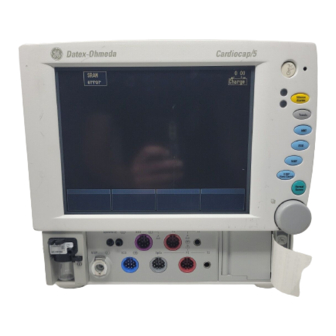
- Page 32 Cardiocap/5 Technical Reference Manual Table of Figures Figure 2-1. Cardiocap/5 monitor (F-MXG) .................2-1 Figure 2-2. Patient connections—Hemodynamic (F-MX)............2-2 Figure 2-3. Patient connections—Hemodynamic with gas (F-MXG)........2-3 Figure 2-4. Rear panel (F-MXG)..................2-4 Figure 2-5. Scavenging through ventilator reservoir ............2-5 Figure 2-6. Connecting sample gas outlet directly to an anesthesia gas scavenging system...2-6 Figure 2-7.
-
Page 33: Chapter 2. Installation And Functional Check
Installation and Functional Check 2. INSTALLATION AND FUNCTIONAL CHECK 2.1 Introduction This chapter includes the information needed to install and check the monitor. Information for connecting other equipment, such as a printer or computer, is also included. If you need assistance concerning the installation, please contact your authorized distributor. -
Page 34: Patient Connectors Panel (F-Mx)
Figure 2-2. Patient connections—Hemodynamic (F-MX) (1) NIBP (2) ECG (3) SpO NOTE: Connector type depends on which SpO option is installed: Connector for Datex-Ohmeda standard pulse oximetry Connector for Datex-Ohmeda enhanced pulse oximetry Connector for Nellcor® compatible pulse oximetry (4) Invasive pressure, P1 (N-XP option) -
Page 35: Patient Connectors Panel (F-Mxg)
(4) Temperature, T2 (N-XP option) (5) Temperature, T1 (6) Invasive pressure, P1 (N-XP option) (7) SpO NOTE: Connector type depends on which SpO option is installed: Connector for Datex-Ohmeda standard pulse oximetry Connector for Datex-Ohmeda enhanced pulse oximetry Connector for Nellcor® compatible pulse oximetry... -
Page 36: Rear Panel
Cardiocap/5 Technical Reference Manual 2.2.2 Rear panel Figure 2-4. Rear panel (F-MXG) (1) Built-in handle (2) Gas outlet (F-MXG only), X6 (3) Remote Control connector, X5 (4) Ethernet connector, X4 (5) Network connection LEDs (6) Network identification plug connector, X3 (7) Serial communication interface/local printer connector, X2 (8) Analog/digital output connector, X1 (includes nurse call and defibrillator synchronization signals) -
Page 37: Connection To Network
2.2.3 Connection to network If either Cardiocap/5 Network option (N-XNET or N-XDNET) is installed, you can connect the Cardiocap/5 to the Datex-Ohmeda Network and iCentral. Use the Monitor-Network cable to connect the monitor to the network. 1. Power off the monitor. -
Page 38: Scavenging Through The Anesthesia Gas Scavenging System
Anesthesia machines are equipped with an anesthesia gas scavenging system (AGSS), and in some machines you can connect the sample gas outlet directly to that. For example, connect the sample gas outlet to the Datex-Ohmeda S/5 Avance: Figure 2-6. Connecting sample gas outlet directly to an anesthesia gas scavenging system Note: Refer to the anesthesia machine’s documentation to find out where and how the sample gas... -
Page 39: Returning Gas To The Patient Circuit
IEC/EN 60601-1-1 and with local requirements. 2.4.1 Interfacing a printer You can connect a PCL-5 compatible laser printer to the Cardiocap/5 using the Datex-Ohmeda Light Monitor–Printer cable. Connect this serial-to-parallel interface cable between the local printer connector (X2) and the printer. -
Page 40: Interfacing A Computer
Cardiocap/5 Technical Reference Manual 2.4.2 Interfacing a computer It is possible to interface a computer to the Cardiocap/5. For further information, please contact your authorized GE Healthcare distributor. WARNING: Connecting the power supply cord of the computer to the wall socket may cause the computer leakage current to exceed the limit specified for medical equipment. -
Page 41: Analog Outputs
Installation and Functional Check Analog outputs Each analog output signal is scaled linearly between –5 and +5 volts. The resolution is 4096 steps over 10 volts, or approximately 0.00244 volts per step. All signal levels are updated every 10 ms. Default state. -
Page 42: Setting The Analog Output Signals
Cardiocap/5 Technical Reference Manual TEST 2 Test signal of a triangle shape with a base width of 4 seconds (–5 V minimum; +5 V maximum). Special indications for analog outputs Start-up indication occurs when the monitor is started by a power on or by an internal restart (caused by a fatal failure). -
Page 43: Connector Pin Assignments
Installation and Functional Check 2.5 Connector pin assignments 2.5.1 Analog/digital output connector (X1) CON./ I/O BOARD SIGNAL DIRECTION LEVEL FUNCTION X1/1 – X1/2 X1/3 DSYNCOUT CMOS Defibrillation sync. X1/4 X1/5 NCALLOUT CMOS Nurse Call X1/6 X1/7 – X1/8 to X1/10 X1/11 NCALLB1 –... -
Page 44: Serial Communication Interface/Local Printer Connector (X2)
Cardiocap/5 Technical Reference Manual 2.5.2 RS-232 serial communication interface/local printer connector (X2) Connector X2 provides an RS-232 serial communication link with handshaking. D9 male connector pinout (front view) CON./ I/O BOARD SIGNAL DIRECTION LEVEL FUNCTION X2/1 – Ground X2/2 RS232 Serial bus, Receive X2/3 RS232... -
Page 45: Ethernet Connector (X4)
Installation and Functional Check 2.5.4 Ethernet connector (X4) The Ethernet interface meets IEEE 802.3 specifications (10BASE-T) with hospital-grade approved power and data transformers. Ethernet connector (front view) SIGNAL DIRECTION FUNCTION Tx + Transmit data Tx – Transmit data Rx + Receive data Rx –... -
Page 46: Functional Check
NOTE: With the N-XNSAT option, use only Nellcor sensors (DS-100A, for example). With the N-XOSAT option, use only Datex-Ohmeda sensors (OXY-F1-H, for example). For standard pulse oximetry, use only Datex-Ohmeda sensors (OXY-F4-N, for example). Simulator capable of simulating ECG, RESP, and invBP... -
Page 47: Functional Inspection
Installation and Functional Check 2.6.1 Functional inspection 1. Connect the power cord. Check that the green external power indicator/battery charge status LED turns on or starts flashing. 2. Switch the monitor on. Check that the monitor starts up as follows: The start-up sound is heard from the loudspeaker •... - Page 48 Cardiocap/5 Technical Reference Manual 5. Check that the supply voltages are within the given limit values: Press the ComWheel to enter the Main Menu and select: Monitor Setup Install/Service (Password 16-4-34) Service View (Password 26-23-8) Monitor Voltages Voltages Mains power ON Mains power OFF VDD/BAT 14.3 to 16.2...
-
Page 49: Recorder Test (If N-Xrec Option Is Included)
Installation and Functional Check Recorder test (if N-XREC option is included) 7. Open the paper compartment cover and check that the “Recorder: Cover open” message is displayed. Close the cover. 8. To record waveforms, press the ComWheel to enter the Main Menu and select: Record/Print Record Waveforms Record Wave... -
Page 50: Network Test (If N-Xnet Or N-Xdnet Option Is Included)
NOTE: If the battery is being charged, the battery charging symbol is displayed instead of the network symbol. A message regarding the connection to the Datex-Ohmeda Information Center should appear in the message field on the screen. 14. To enter the Communication service menu and check Network information, press the ComWheel... -
Page 51: Ecg Board Test
Installation and Functional Check ECG board test 16. Enter the ESTP: ECG service menu: To return to the Service View menu, select Previous Menu as needed until you can select Modules and then select ESTP : ECG. Press the ComWheel and select: Monitor Setup Install/Service (Password 16-4-34) - Service View (Password 26-23-8) -
Page 52: Nibp Board Test
Connect the appropriate SpO finger sensor to the monitor (use a Nellcor sensor for the N-XNSAT option; a Datex-Ohmeda sensor for the N-XOSAT option). Attach the sensor to your finger. Check that an acceptable SpO reading and a proper SpO waveform appear on the screen. -
Page 53: Gas Measurement And Spirometry Test
Installation and Functional Check Gas measurement and spirometry test 25. Connect a sample line to the D-fend. If the monitor is configured with Patient Spirometry (N-XV option), press the ComWheel to enter the Main Menu and select: Monitor Setup Screen 1 Setup Waveform Field Field 2 (choose Paw) Field 3 (choose Flow) -
Page 54: Neuromuscular Transmission (Nmt) Test (If N-Xnmt Option Is Included)
Cardiocap/5 Technical Reference Manual NeuroMuscular Transmission (NMT) test (if N-XNMT option is included) 29. Cycle power to the monitor and wait until the normal monitoring screen appears. Then, configure the monitor for NMT measurement: Press the ComWheel and select Monitor Setup. •... - Page 55 Installation and Functional Check 33. Start NMT measurement (TOF) by selecting NMT Setup and selecting Start-up. Press Previous Menu to return to the NMT service menu. In the digit field, when the “Supramax search” message changes to “Setting reference,” check that the detected supramaximal current is less than 70 mA (the Current set value on the service screen is less than 700).
-
Page 56: Performance Checks
Cardiocap/5 Technical Reference Manual 2.6.2 Performance checks 1. Configure the monitor screen to display all parameter information. Press the ComWheel to enter the Main Menu and select: Monitor Setup – Screen Setup – Waveform Fields/Digit Fields An example is shown below: Waveform Fields Digit Fields Field 1 –... - Page 57 Installation and Functional Check 3. Set the invBP simulator to +100 mmHg (+13.3 kPa) static pressure. Push the ZERO button and check that: The invBP waveforms set on the baseline. • The digital values go to zero. • Set the simulator to 0 mmHg (0 kPa) and press ZERO. After the zeroing is completed, turn the simulator to dynamic mode and check that the waveform is normal.
- Page 59 Hemodynamic model with gas measurement Monitor model: F-MX F-MXG Measurement options Measurement options (SpO 2 ) N-XP Two invasive pressure channels and N-XOSAT Datex-Ohmeda enhanced pulse second temperature (T2) oximetry N-XC N-XNSAT Nellcor compatible pulse oximetry N-XCO O, Patient Oxygen...
- Page 60 Functional Check Form N.A. Fail Recorder test 7. Recorder message 8. Recording Memory card (PCMCIA) test 9. Memory 10. Communication 11. Memory card recognition Network test 12. Connection to network 13. Communication 14. Data error counters 15. Hardware error counters ECG board test 16.
- Page 61 Functional Check Form NeuroMuscular Transmission (NMT) test N.A. Fail 29. Recognition 30. Communication and memory 31. ElectroSensor recognition 32. Stimulus current test 33. TOF measurement with NMT simulator 950-1059 Supramax. current < 70 mA 950-1059 TOF% 95-105 950-1059 Count 950-1059 95-105 Ratio% 950-1059...
- Page 62 Functional Check Form Performance Checks General N.A. Fail 1. Screen setup 2. Waveforms InvBP measurement 3. Test with patient simulator measurement 4. SpO sensor detection 5. Test measurement 6. “Probe off” detection NIBP measurement 7. Test measurement and cuff identification Gas measurement 8.
- Page 63 EMC Guidance EMC GUIDANCE Table 1. Guidance and manufacturer’s declaration – electromagnetic emissions Guidance and manufacturer’s declaration – electromagnetic emissions The Cardiocap/5 is intended for use in the electromagnetic environment specified below. The customer or the user of the Cardiocap/5 should assure that it is used in such an environment. Emissions test Compliance Electromagnetic environment - guidance...
- Page 64 Functional Check Form Table 2. Guidance and manufacturer’s declaration – electromagnetic immunity Guidance and manufacturer’s declaration – electromagnetic immunity The Cardiocap/5 is intended for use in the electromagnetic environment specified below. The customer or the user of the Cardiocap/5 should assure that it is used in such an environment. Immunity test IEC 60601 test Compliance level...
- Page 65 EMC Guidance Table 3. Guidance and manufacturer’s declaration – electromagnetic immunity Guidance and manufacturer’s declaration – electromagnetic immunity The Cardiocap/5 is intended for use in the electromagnetic environment specified below. The customer or the user of the Cardiocap/5 should assure that it is used in such an environment. Immunity test IEC 60601 test Compliance...
- Page 66 Functional Check Form Table 4. Recommended separation distances between portable and mobile RF communications equipment and the Cardiocap/5. Recommended separation distances between portable and mobile RF communications equipment and the Cardiocap/5. The Cardiocap/5 is intended for use in an electromagnetic environment in which radiated RF disturbances are controlled.
- Page 67 Contents Chapter 3. Planned Maintenance 3.1 Introduction................. 3-1 3.1.1 Using the Planned Maintenance Form ............3-1 3.1.2 Recommended parts................... 3-1 3.1.3 Recommended tools and accessories ............3-2 3.2 Planned maintenance checks..........3-3 1. Visual inspection.................. 3-3 2. Parts replacement ................3-3 3.
-
Page 69: Chapter 3. Planned Maintenance
Planned Maintenance 3. PLANNED MAINTENANCE 3.1 Introduction These instructions include procedures for planned maintenance (PM) of the Datex-Ohmeda Cardiocap/5 monitor. Performance of planned maintenance procedures is recommended once each year after installation of the monitor. These instructions are for the maximum functional configuration of the monitor. Perform the procedures in order and skip items that do not correspond with the configuration of your monitor. -
Page 70: Recommended Tools And Accessories
Cardiocap/5 Technical Reference Manual 3.1.3 Recommended tools and accessories Tool Order Number Patient simulator for ECG, Impedance Respiration, and BP Obtain locally Pressure manometer Obtain locally Temperature test set 884515 5-lead ECG cable Obtain locally finger sensor (compatible with the installed pulse oximetry) Obtain locally InvBP transducer Obtain locally... -
Page 71: Planned Maintenance Checks
2. Replace these items in the gas unit: occlusion filter, zero absorber, Nafion tubing, and OM reference filter. Also replace the D-fend, D-fend O-ring, and sampling line. NOTE: Use only Datex-Ohmeda sampling lines to ensure proper function. Occlusion filter OM reference... -
Page 72: Functional Inspection
Cardiocap/5 Technical Reference Manual 3. Functional inspection 1. Connect the power cord and check that the Battery charge status LED turns on or flashes. 2. Switch on the monitor and check that it starts up as described below: • Both alarm LEDs flash On and Off. •... -
Page 73: Ecg Measurement Test
Planned Maintenance 4. Check the capacity time of the backup battery: Disconnect the power cord (without switching the monitor to standby). Note the time and make sure that the monitor continues to run normally with the battery for at least 15 minutes. The battery indicator should appear on the screen: NOTE: You can continue the check while the monitor is powered by batteries. -
Page 74: Non-Invasive Blood Pressure (Nibp) Measurement Test
Cardiocap/5 Technical Reference Manual 6. Non-invasive blood pressure (NIBP) measurement test NOTE: See the Service Menus chapter for illustrations of the service menus used for the NIBP test. 1. Return to the Modules service menu and select NIBP to enter the NIBP service menu. Check that NIBP board memories passed the internal memory test (RAM, ROM, and EEPROM all state OK). -
Page 75: Invasive Blood Pressure Measurement Test
NOTE: Do not calibrate the gas measurement until the monitor has warmed up for 30 minutes. 10. Anesthetic agent identification test NOTE: Use only the recommended Datex-Ohmeda calibration gas (see Recommended tools and accessories earlier in this chapter). While displaying the Gases service menu, feed the calibration gas continuously for at least 30 seconds and check that the screen shows: The ID. -
Page 76: Spirometry Test
Cardiocap/5 Technical Reference Manual 11. Spirometry test 1. Perform the spirometry leakage test and calibration (see section 7.4.9). 2. With a sample line attached to the D-lite sensor, breathe through the wider side of the D-lite. Check that the flow waveform moves downward when you breathe in, and upward when you breathe out. -
Page 77: Network Test
Yellow --> should flash intermittently Green --> should be lit continuously 2. Check that the monitor connects to the Datex-Ohmeda Network (that is, the network symbol is displayed on the upper right corner of the screen). NOTE: If the battery is being charged, the battery charging symbol is displayed instead of the network symbol. -
Page 78: Data Card Test
Cardiocap/5 Technical Reference Manual 17. Data card test 1. Insert a memory card labeled "Menu" into the front-most memory card slot. Check that the “Menu card inserted” message appears in the message field. 2. Insert a memory card labeled "Data" into the second slot. Check that the "Data card inserted" message appears in the message field. -
Page 79: Planned Maintenance Form
Hemodynamic model Hemodynamic model with gas measurement F-MX F-MXG Measurement options Measurement options (SpO 2 ) N-XP Two invasive pressure channels and N-XOSAT Datex-Ohmeda enhanced pulse second temperature (T2) oximetry N-XC N-XNSAT Nellcor compatible pulse oximetry N-XCO O, Patient Oxygen... - Page 80 Planned Maintenance Form N.A. Fail 3. Functional inspection 4. ECG measurement test 5. Temperature measurement test 6. Non-invasive blood pressure (NIBP) measurement test 7. SpO measurement test 8. Invasive blood pressure measurement test 9. Gas measurement test 10. Anesthetic agent identification test 11.
- Page 81 Contents Chapter 4. Troubleshooting 4.1 Messages ................4-1 4.2 Troubleshooting charts ............4-7 4.2.1 Start-up troubleshooting ................4-7 4.2.2 General...................... 4-8 4.2.3 ECG ......................4-8 4.2.4 Impedance respiration ................4-9 4.2.5 Pulse oximetry (SpO ), standard..............4-9 4.2.6 NIBP ......................4-9 4.2.7 Temperature....................
-
Page 83: Chapter 4. Troubleshooting
Troubleshooting 4. TROUBLESHOOTING See the User’s Reference Manual for more messages and troubleshooting procedures. 4.1 Messages MESSAGE POSSIBLE CAUSE ACTION Acknowl. alarms Acknowledged alarms are silenced (Silence No action required. silenced Alarms key pressed during silencing period). Air leakage Hose and/or cuff leaking. Damaged cuff, cuff Replace cuff, cuff connector, and/or connector, or hose double connector. - Page 84 Cardiocap/5 Technical Reference Manual MESSAGE POSSIBLE CAUSE ACTION Call service: Error X 1 ROM checksum error; memory failure Change NIBP board. (X = the NIBP hardware error number shown in Check short circuits. Change NIBP 2 + 15 V failure. next column) board.
- Page 85 Troubleshooting MESSAGE POSSIBLE CAUSE ACTION Cuff loose (NIBP) Hose and/or cuff not connected. Connect the hose and the cuff. Cuff loosely wrapped. Tighten the cuff. Leakage in cuff or hose. Replace cuff/hose. Leakage inside module. Check/fix internal tubing and air chamber.
- Page 86 Cardiocap/5 Technical Reference Manual MESSAGE POSSIBLE CAUSE ACTION NIBP measurement Signal cable is loose or not attached. Check signal cable connections from Mother board to CPU board. removed Invasive pressure or transducer cable not Connect invasive pressure or transducer No P1/P2 transducer connected.
- Page 87 Troubleshooting MESSAGE POSSIBLE CAUSE ACTION Response too weak (NMT) The maximum gain is insufficient to Reposition the stimulating or recording increase the response signal amplitude to a electrodes. Change the site of the measurable level. This can occur if: measuring electrodes. •...
- Page 88 Cardiocap/5 Technical Reference Manual MESSAGE POSSIBLE CAUSE ACTION Unstable zero pressure Pressure is unstable when starting the NIBP Calm the patient and retry. measurement. Erroneous voltage level detected. Replace power supply unit. Voltage error Weak or unstable oscillation pulses due to: Check patient condition;...
-
Page 89: Troubleshooting Charts
Troubleshooting 4.2 Troubleshooting charts 4.2.1 Start-up troubleshooting No picture on screen NOTES ⇓ Check that the mains power is 100 to 240VAC. If the mains power is too low or high the power supply does not work. Check that the mains fuses have not blown. Fuse type has to be T2AH. -
Page 90: General
Cardiocap/5 Technical Reference Manual 4.2.2 General SITUATION POSSIBLE CAUSE ACTION Keyboard and ComWheel Keyboard and ComWheel cables Detach monitor rear cover and check the are not working not connected to CPU board. cable connections to the CPU. Faulty CPU. Replace the CPU if the cable connections are OK Keyboard is not working Keyboard cable not properly... -
Page 91: Impedance Respiration
Troubleshooting 4.2.4 Impedance respiration SITUATION POSSIBLE CAUSE ACTION No resp trace Waveform not selected on the Adjust (Monitor Setup – Screen Setup – screen. Waveform Fields). Unacceptable resp Poor electrode or poor electrode Electrodes from different manufacturers waveform skin contact. are used. -
Page 92: Troubleshooting Charts For Options
Cardiocap/5 Technical Reference Manual 4.3 Troubleshooting charts for options 4.3.1 Recorder (N-XREC) SITUATION POSSIBLE CAUSE ACTION Recorder not responding to Membrane switch cable loose or Check the cable. Replace the front panel if front panel key but operates broken. necessary. through Recorder menu. -
Page 93: Pulse Oximetry (N-Xosat Or N-Xnsat)
Troubleshooting 4.3.3 Pulse oximetry (N-XOSAT or N-XNSAT) 4-11... -
Page 94: Airway Gases (N-Xc, N-Xco, Or N-Xcaio)
Cardiocap/5 Technical Reference Manual 4.3.4 Airway gases (N-XC, N-XCO, or N-XCAiO) SITUATION POSSIBLE CAUSE ACTION Air leak detected. Air leak over 40 seconds. Check water trap and sample gas outflow. Press Normal Screen to continue. Continuous occlusion. Occlusion over 40 seconds. Check sampling line and D-fend. -
Page 95: Patient Spirometry (N-Xv)
Troubleshooting 4.3.5 Patient Spirometry (N-XV) SITUATION POSSIBLE CAUSE ACTION insp TV>exp TV Spirometry tube leak. Check leaks; perform leak test. Water inside D-lite or tubing. Change tubing and D-lite. Another side-stream gas sampling between Don’t use active humidification. D-lite and patient. D-fend leaks. -
Page 96: Neuromuscular Transmission (N-Xnmt)
Cardiocap/5 Technical Reference Manual 4.3.6 NeuroMuscular Transmission (N-XNMT) 4-14... - Page 97 Contents Chapter 5. Frames and Software 5.1 Introduction................. 5-1 5.1.1 Cardiocap/5 measurement options ............. 5-1 5.2 AC/DC power supply functional description ......5-2 5.2.1 Introduction ....................5-2 5.2.2 Main structure .................... 5-3 5.2.3 PFC converter ..................... 5-3 5.2.4 DC/DC converter ..................5-4 5.2.5 Start-up sequence ..................
- Page 98 Cardiocap/5 Technical Reference Manual 5.5.2 Asynchronous serial channels ..............5-18 Serial channels implemented with PLD (D19) ..........5-19 Serial channels of the Quart ...............5-19 5.5.3 Keyboards and ComWheel.................5-19 Keyboard interface ..................5-19 Matrix keyboard ..................5-19 ComWheel....................5-19 5.5.4 Digital I/O signals ..................5-20 Defibrillator synchronization output ............5-20 Alarm signals ....................5-20 5.5.5 Display controller ..................5-21 5.5.6 Memory....................5-21...
-
Page 99: Chapter 5. Frames And Software
, anesthetic agents, agent identification, N O, Patient Oxygen • N-XV Patient Spirometry NOTE: This option requires N-XCO or N-XCAiO. • N-XNMT NeuroMuscular Transmission NOTE: This option requires N-XCAiO. • • N-XOSAT Datex-Ohmeda enhanced pulse oximetry • • N-XNSAT Nellcor® pulse oximetry... -
Page 100: Ac/Dc Power Supply Functional Description
Cardiocap/5 Technical Reference Manual 5.2 AC/DC power supply functional description 5.2.1 Introduction The AC/DC unit SR92A720 is a switched-mode power supply made by Efore Ltd. Figure 5-1. AC/DC unit The AC/DC switched-mode power supply unit SR92A720 is an integrated part of a patient monitoring device. -
Page 101: Main Structure
Frames and Software 5.2.2 Main structure The general schematic structure of the SR92A720 power supply is shown below. 100...240V~ 15.7V/4A X12-4 INPUT FILTER X12-5 X12-1 Inrush resistor X12-2 Gate drive Gate drive X12-3 External shutdown signal X12-6 External feedback signal Figure 5-2. -
Page 102: Dc/Dc Converter
Cardiocap/5 Technical Reference Manual The PFC converter controls the intermediate voltage. The intermediate voltage has been set to about 370 V. In addition, there is a small (<10 V ) ac ripple component across capacitor C9. The frequency of this AC component is double the line frequency. 5.2.4 DC/DC converter The DC/DC converter is a forward converter. -
Page 103: Over-Voltage Protection
Frames and Software Output voltage is controlled by a two-loop system. This means that there is a fast inner-voltage- control loop and a slow outer-voltage-control loop. The slow-voltage control is an external voltage signal, which, by setting the offset to the inner-control loop, determines the level of the output voltage. If the external feedback signal is not connected to pin 6 of connector X12, the output voltage measured from connector X12 settles to approximately 10 V. -
Page 104: Dc/Dc Board Functional Description
Cardiocap/5 Technical Reference Manual 5.3 DC/DC board functional description 5.3.1 Introduction The DC/DC board converts the output voltage of the AC/DC power supply or the battery voltage to various supply voltages for the electronics of Cardiocap/5 monitor. Another main task of the board is battery charging. -
Page 105: Dc/Dc Board Block Diagram
Frames and Software 5.3.2 DC/DC board block diagram The input voltages of the board are VDD (from the AC/DC power supply) and BAT (the battery voltage). The DC/DC board trims the level of VDD. Switching power supplies convert VDD or BAT to supply voltages for monitor electronics. - Page 106 Cardiocap/5 Technical Reference Manual Figure 5-7. DC/DC board power supplies...
-
Page 107: Detailed Description Of The Power Supplies
Frames and Software 5.4 Detailed description of the power supplies Synchronous switching is used in all step-down (buck) type switching power supplies in order to improve the efficiency. In synchronous switching (or synchronous rectification), the normal schottky diode of a buck converter is bypassed by a FET conducting at the same time as the diode. This reduces diode loss remarkably. -
Page 108: 15Vd Power Supply
Cardiocap/5 Technical Reference Manual 5.4.5 +15VD power supply +15VD is used as a “dirty” +15V supply in the monitor. It powers the thermal printer, DC motors, pneumatic valves, and isolated switching power supplies. On the DC/DC board, the regulated voltage is actually +15VB, which is named +15VD after circuit breaker electronics. -
Page 109: Cpu Power Connector (X6)
Frames and Software CPU power connector (X6) SIGNAL/VOLTAGE DESCRIPTION X6/1 X6/2 X6/3 +3.3V To CPU and 3.3V LCD display X6/4 +3.3V X6/5 +3.3V X6/6 +3.3V X6/7 X6/8 X6/9 To CPU and 5V LCD display X6/10 X6/11 X6/12 X6/13 +12V To LCD backlight inverter X6/14 Mother board power connector (X2) SIGNAL/VOLTAGE... -
Page 110: Ac/Dc Power Supply Connector (X8)
Cardiocap/5 Technical Reference Manual AC/DC power supply connector (X8) SIGNAL/VOLTAGE DESCRIPTION X8/1 VDD_SHUTDOWN/ Shut AC/DC power s. X8/2 X8/3 X8/4 TRIM_VDD Adjust VDD X8/5 AC/DC output voltage X8/6 5.4.6 Fan control The supply voltage VFAN is linearly regulated from +15VD. The operating voltage range of the fan used is 10.2 to 13.8V. -
Page 111: Battery Connector (X4)
Frames and Software A CPU control signal (ICHGLOW) reduces the maximum charge current. This can be used momentarily to cut the power consumption peaks of the monitor. Battery connector (X4) SIGNAL/VOLTAGE DESCRIPTION X4/1 Battery voltage X4/2 X4/3 X4/4 5.4.8 Control electronics The main functions of the control and measuring electronics are listed below: •... -
Page 112: Cpu Connector (X7)
Cardiocap/5 Technical Reference Manual CPU connector (X7) SIGNAL DESCRIPTION X7/1 ON/STBY_1 STBY switch end 1 X7/2 STBY switch end 2 X7/3 STOP/ Shut +3.3V and +5V switchers X7/4 POW_WD Watchdog refresh X7/5 EN_VIN12V Enable VIN_12V X7/6 EN_12V Enable +12V X7/7 EN_15VB Enable VIN_15VB and boost conv. -
Page 113: Ad Converter
Frames and Software 5.4.9 AD converter The analog-to-digital converter is controlled by the CPU via a slow serial data bus. The signals are SSCLK (clock), SSDOUT (CPU data out), SSDIN (CPU data in), and ADC_CS/ (chip select). The A/D converter is an 11-channel, 12-bit circuit. It uses external reference voltage. On the DC/DC board, the reference voltage is RC-filtered from +5V_INT supply. -
Page 114: Cpu Board
Cardiocap/5 Technical Reference Manual 5.5 CPU board The CPU board performs central data processing of the Cardiocap/5 monitor. The CPU board is based around an embedded AMD ELAN SC 410 (66MHz) processor. The memory chips listed below are located on the CPU board: •... - Page 115 Frames and Software AMD ELAN SC 410 ( 66MHz) Crystal Digital - 486 core + 8kbyte cache 32kHz - DRAM controller - 3 x Timer/Counter - 1 x UART(IrDA) - 2 x Interrupt Controller JTAG - DMA Controller IrDA test - ISA &...
-
Page 116: Synchronous Serial Communication
Cardiocap/5 Technical Reference Manual 5.5.1 Synchronous serial communication The CPU board contains two separate synchronous serial channels. Channel one handles communication with the Ethernet ID-block (if available). Channel two is the internal serial bus of the monitor. The synchronous serial channels are implemented with PLD to minimize the load of the main processor. -
Page 117: Serial Channels Of The Quart
Frames and Software Serial channels implemented with PLD (D19) Module Bus PLD and Main Software control the function of the Module Bus and the Universal Peripheral Interface (UPI). This way the interrupts generated by the serial communication will not load the main processor. The Module Bus Reset comes from PLD pin 105. -
Page 118: Digital I/O Signals
Cardiocap/5 Technical Reference Manual 5.5.4 Digital I/O signals The different I/O-signals have been split into groups according to their function: • Defibrillator synchronization output. • Alarm signals. • PWR-board control signals. Defibrillator synchronization output Each detected QRS complex generates a 10 ms long, 5V pulse to pin 3 of the rear panel 44-pin I/O connector. -
Page 119: Display Controller
Frames and Software 5.5.5 Display controller The display controller chip is a VGA-compatible chip 65550. Two 256k x 16 display memories connected to the display controller enable use of a 32-bit databus for addressing display memory. The display controller is directly connected to the VESA Local bus (VL-Bus) of the processor. In addition to the control signals, the supply voltages (VEE_S &... -
Page 120: Pc And Ethernet Interfaces
Cardiocap/5 Technical Reference Manual 5.5.7 PC and ethernet interfaces PC card The PC card interface, a Cirrus PCMCIA controller CL-PD6722, drives two PC cards. It is connected to the ISA bus of the processor. The PC-Card interface accepts standard +3.3 V or +5 V cards. The controller selects the correct voltage automatically. -
Page 121: Display, Input, And Output
Frames and Software 5.6 Display, input, and output 5.6.1 Display NOTE: The LCD display backlight circuit runs on high voltage. Do not touch the inverter board when powered. The display consists of 10.4 inch TFT LCD display unit, backlight board, and inverter board. The CPU board drives the display. -
Page 122: I/O Board
Cardiocap/5 Technical Reference Manual 5.6.4 I/O board The I/O board contains four different I/O connectors: • 44-pin female D connector for digital/analog output. • 9-pin male D connector for RS-232 serial I/O. • 9-pin female D connector for connecting NET ID plug. •... -
Page 123: Recorder And Recorder Board (N-Xrec Option)
Frames and Software 5.7 Recorder and recorder board (N-XREC option) You can use the optional built-in recorder to do the following: • Record the graphical or numerical trend and print up to 24 hours of trend data. • Record up to three real-time waveforms simultaneously. •... - Page 124 Cardiocap/5 Technical Reference Manual 5-26...
- Page 125 6.2.6 Pulse oximetry, standard ................6-4 Plethysmographic pulse wave ..............6-5 Sensor ....................... 6-5 Pulse rate ....................6-5 6.2.7 Pulse oximetry, Datex-Ohmeda enhanced (N-XOSAT option)......6-5 Calibration ....................6-6 6.2.8 Pulse oximetry, Nellcor compatible (N-XNSAT option) ........6-7 6.3 Measurement principles for airway gases, spirometry, and NMT ................
- Page 126 6.4.6 STP board—Temperature measurement section ...........6-22 6.4.7 STP board—Invasive blood pressure measurement section ......6-23 6.5 N-XOSAT or N-XNSAT optional pulse oximetry components ..6-24 6.5.1 Datex-Ohmeda enhanced pulse oximetry components (N-XOSAT option)..6-24 Serial communications connector...............6-24 Sensor interface connector ................6-24 6.5.2 Nellcor pulse oximetry components (N-XNSAT option) ........6-25 Communication protocol jumper ..............6-25...
- Page 127 Contents Table of Figures Figure 6-1. Hemodynamic parameters measurement unit (NESTPR)........6-1 Figure 6-2. Airway gases measurement unit ..............6-2 Figure 6-3. Absorption of infrared light in the finger ............6-4 Figure 6-4. Comparative light absorption ................6-6 Figure 6-5. Extinction versus wavelength graph..............6-6 Figure 6-6.
-
Page 129: Chapter 6. Measurement Parameters
P = Invasive blood pressure (N-XP option)—two channels (P1, P2) and a second temperature (T2) R = Impedance respiration The pulse oximetry options listed below require hardware and processing that is not part of the NESTPR unit: • Datex-Ohmeda enhanced pulse oximetry (N-XOSAT option). • Nellcor® compatible pulse oximetry (N-XNSAT option). -
Page 130: Airway Gases And Associated Options
Cardiocap/5 Technical Reference Manual 6.1.2 Airway gases and associated options The Cardiocap/5 Airway Gas options (N-XC, N-XCO, N-XCAiO) provide airway and respiratory measurements through the airway gas measurement unit. Figure 6-2. Airway gases measurement unit The features of each option are noted in the chart below. NOTE: One or more of the airway gas options is required for the Patient Spirometry (N-XV) and NeuroMuscular Transmission (N-XNMT) options. -
Page 131: Measurement Principles For Hemodynamic Parameters
Measurement Parameters 6.2 Measurement principles for hemodynamic parameters 6.2.1 NIBP NIBP (Non-Invasive Blood Pressure) is an indirect method for measuring blood pressure. The NIBP measurement is performed according to the oscillometric measuring principle. The cuff is inflated with a pressure slightly higher than the presumed systolic pressure and deflated at a speed based on the patient's pulse. -
Page 132: Invasive Blood Pressure (N-Xp Option)
Cardiocap/5 Technical Reference Manual 6.2.5 Invasive blood pressure (N-XP option) A catheter is inserted into an artery or vein to measure invasive blood pressure. The invasive pressure setup—consisting of tubing, a pressure transducer, and an intravenous bag of normal saline all connected together by stopcocks—is attached to the catheter. -
Page 133: Sensor
NOTE: Only one pulse oximetry source at a time is allowed by the Cardiocap/5. When the N-XOSAT option is installed in the monitor, standard pulse oximetry and N-XNSAT are not available. The Datex-Ohmeda enhanced pulse oximetry option uses a two-wavelength pulsatile system—red and infrared light—to distinguish between oxygenated (O Hb) and reduced (HHb) hemoglobin, each of which absorbs different amounts of light emitted from the oximeter sensor. -
Page 134: Calibration
Calibration Datex-Ohmeda enhanced pulse oximetry uses two wavelength ranges, 650 nm to 665 nm and 930 nm to 950 nm, both with an average power of less than 1 mW. These wavelengths are used to calculate the presence of oxyhemoglobin (O Hb) and reduced hemoglobin (HHb). -
Page 135: Pulse Oximetry, Nellcor Compatible (N-Xnsat Option)
The calculation of SpO assumes 1.6% carboxyhemoglobin (COHb), 0.4% methemoglobin (MetHb), and no other pigments. These values are based on the Datex-Ohmeda Pulse Oximeter Empirical Calibration Study. Appreciable variation from these values will influence SpO accuracy. -
Page 136: Measurement Principles For Airway Gases, Spirometry, And Nmt
Cardiocap/5 Technical Reference Manual 6.3 Measurement principles for airway gases, spirometry, and NMT 6.3.1 CO O, and agent measurement TPX is a side-stream gas analyzer that measures real-time concentrations of CO O and anesthetic agents (Halothane, Enflurane, Isoflurane, Desflurane, and Sevoflurane). The TPX analyzer identifies anesthetic agents or mixtures of two anesthetic agents and measures their concentrations. -
Page 137: Measurement
Measurement Parameters Figure 6-8. Infrared absorbance of AAs To achieve measuring accuracy, numerous software compensation parameters are individually determined for each TPX during factory calibration. 6.3.2 O measurement The differential oxygen measuring unit uses the paramagnetic principle in a pneumatic bridge configuration. -
Page 138: Patient Spirometry Measurement
Cardiocap/5 Technical Reference Manual 6.3.3 Patient spirometry measurement In mechanical ventilation, breaths are delivered to the patient by a ventilator with a proper tidal volume, respiration rate (RR), and inspiration/expiration ratio in a time determined by the ventilator settings. Patient Spirometry monitors patient ventilation and displays these parameters: •... -
Page 139: Compliance And Airway Resistance
Measurement Parameters Compliance and airway resistance Compliance tells how big a pressure difference is needed to deliver a certain amount of gas into the patient. Compliance is calculated for each breath from the following equation: TVexp Compl − − PEEPi PEEPe plat The airway resistance, Raw, is calculated using an equation that describes the kinetics of the gas flow between the lungs and the D-lite flow sensor. -
Page 140: Neuromuscular Transmission (Nmt) Measurement
Cardiocap/5 Technical Reference Manual 6.3.4 NeuroMuscular Transmission (NMT) measurement The NMT feature provides peripheral nerve stimulation and response measurement that supports electromyography EMG. You can also use the Cardiocap/5 NMT feature as a nerve locator for regional nerve blocking with a regional block cable, however, in this case there is no response measurement. Nerve stimulation There are three NMT stimulus modes: Train of Four (TOF), Double Burst 3,3 (DBS) and Single Twitch (ST). -
Page 141: Regional Block
Measurement Parameters Before each stimulation, the sequence offset, noise, and threshold for response detection is measured. Offset is a baseline of the noise measurement. Noise is calculated by the same algorithm as the response signal itself. The response detection threshold is calculated based on the noise. If the response is not greater than the threshold, it is interpreted as no response. -
Page 142: Components For Nestpr Hemodynamic Parameters
Cardiocap/5 Technical Reference Manual 6.4 Components for NESTPR hemodynamic parameters 6.4.1 Serial communication NESTPR Figure 6-11. Serial communication and opto isolation Serial communication between the NESTPR unit and the CPU is done by a RS485-type bus whose buffers get their supply voltage (+5 VDC) from the DC/DC board. In the isolation section, their supply voltage (+5 V) is obtained from the isolated power supply. -
Page 143: Nibp Board
Measurement Parameters 6.4.2 NIBP board Address Bus Figure 6-12. NIBP board functional block diagram Pressure transducers The NIBP board contains two piezo-resistive pressure transducers (B1 and B2). Transducer B1 measures the pressure of the blood pressure cuff and the pressure fluctuations caused by arterial wall movement. -
Page 144: Software Control
Cardiocap/5 Technical Reference Manual Software control Software controls the valves and pump. In addition to ON/OFF signals for each component, a common power switch for the valves and the pump is used at pump/valve failures. Memory NIBP program memory (EPROM) size is 128k × 8. The RAM (32k × 8 bit) stores variable NIBP measurement values. -
Page 145: Ecg Board
Measurement Parameters 6.4.3 ECG board Patient signals are connected to overload protection circuits (resistors and gas-filled surge arresters) and analog switches to instrumentation amplifiers. The signals are amplified by 480 and limited by slew rate. Then they are A/D-converted, analyzed, and transferred to the module bus in digital form. Figure 6-13. -
Page 146: Analog Ecg Section
Cardiocap/5 Technical Reference Manual Analog ECG section The ECG cable is connected to connector pins E1 to E6 on the input board, which contains an overload protection circuit. Analog switches connect leads to amplifiers. The state of the switches depends on the cable type. Lead-off, noise, and pacemaker are detected by a slew rate detector. -
Page 147: Microprocessor Section
Measurement Parameters When the 5-lead cable is used, the current source is between L-F and the signal is measured from the N, independently on the lead selection. The respiration amplifier consists of the operational amplifiers and the components around them. An analog switch controls the gain of the first stage of the preamplifier. -
Page 148: Stp Board
Cardiocap/5 Technical Reference Manual 6.4.4 STP board To NIBP Board Figure 6-14. STP board block diagram Microprocessor unit The STP board uses an Intel 80C196KC-16 processor with three A/D converters, external memories, an 8-bit data bus, a 16 MHz oscillator, an open collector reset, and a watchdog timer. The processor's internal UART communicates with the CPU board. -
Page 149: Stp Board-Pulse Oximetry Measurement Section
Measurement Parameters Isolation section The outputs of the two opto isolators are analog signals in the isolated section, however, the signal is processed on logical high-low level. Reset line is an open collector type with a pull-up resistor, allowing the processor to use its internal watchdog function. Power supply section Isolated supply voltages of the boards are developed from +15 Vdirty voltage from the DC/DC board. -
Page 150: Stp Board-Temperature Measurement Section
Cardiocap/5 Technical Reference Manual LED driving circuit The differential amplifier circuit measures the voltage difference that corresponds to the LED current. Its output is sent back to the processor in 0 to 5 V level. There are feedback circuits from LED current measurement and LED intensity control. -
Page 151: Stp Board-Invasive Blood Pressure Measurement Section
Measurement Parameters 6.4.7 STP board—Invasive blood pressure measurement section Isolated +5 V voltage is supplied to the pressure transducer. From the bridge connection a differential voltage, which depends on pressure and supplied voltage, is calculated (see the formula below). Uout = Uin × Pressure × 5 V where Uin = 5 V Uout = 25 V ×... -
Page 152: N-Xosat Or N-Xnsat Optional Pulse Oximetry Components
6.5 N-XOSAT or N-XNSAT optional pulse oximetry components 6.5.1 Datex-Ohmeda enhanced pulse oximetry components (N-XOSAT option) The Datex-Ohmeda enhanced pulse oximetry option (N-XOSAT) consists of the following parts: • Sensor connector board and cable assembly • Datex-Ohmeda pulse oximetry board (OSAT board) •... -
Page 153: Nellcor Pulse Oximetry Components (N-Xnsat Option)
Measurement Parameters 6.5.2 Nellcor pulse oximetry components (N-XNSAT option) The Nellcor compatible pulse oximetry option (N-XNSAT consists of the following parts: • Sensor connector board and cable assembly • Nellcor pulse oximetry board (NSAT board) • SpO interface board Sensors can be plugged into the monitor directly or used with sensor extension cables available from Nellcor. -
Page 154: Spo Interface Board (For N-Xosat Or N-Xnsat Option)
Cardiocap/5 Technical Reference Manual 6.5.3 SpO interface board (for N-XOSAT or N-XNSAT option) Figure 6-18. SpO interface board block diagram NOTE: Two switches located on the board are not used and have no function with the Cardiocap/5. RS485 drivers The SpO interface board contains drivers for data and for module reset functions. -
Page 155: Opto Isolation
Measurement Parameters Opto isolation The serial communication bus signals between the pulse oximetry board and the Central Unit are transferred through the patient isolation section by high speed opto couplers. Microprocessor, UART, nonvolatile memory The microprocessor, with on-chip memory, converts and transfers data from the pulse oximetry board to the monitor. -
Page 156: Airway Gases And Spirometry Components
Cardiocap/5 Technical Reference Manual 6.6 Airway gases and spirometry components Airway gas measurement involves the following components: • Gas sampling system • TPX measuring unit • OM measuring unit and OM board • PVX measuring unit and PVX board for Patient Spirometry (N-XV option) •... - Page 157 Measurement Parameters Figure 6-20. Gas sampling system (N-XCO and N-XCAiO options) D-fend The sample is drawn through a sampling line to the water trap, where it is separated into a main flow and a side flow. The main flow is drawn through into the analyzers. A hydrophobic filter separates this flow from the patient side.
- Page 158 Cardiocap/5 Technical Reference Manual Sample flow differential pressure transducer The sample flow differential pressure transducer measures pressure drop across the OM inlet restrictor and calculates sample flow from the pressure difference. Working pressure transducer The working pressure transducer measures absolute working pressure between the TPX unit and the OM unit.
-
Page 159: Tpx Measuring Unit
Measurement Parameters 6.6.2 TPX measuring unit The TPX unit is a non-dispersive infrared analyzer, measuring absorption of the gas sample at seven infrared wavelengths, which are selected using optical narrow band filters. The IR lamp is a 4W filament, surrounded by thermal isolation. A hole in the isolation passes the radiation to a conical, 4 mm long measuring chamber. -
Page 160: Pvx Measuring Unit And Board (Patient Spirometry, N-Xv Option)
Cardiocap/5 Technical Reference Manual 6.6.4 PVX measuring unit and board (Patient Spirometry, N-XV option) NOTE: Never apply overpressure or negative pressure of more than 300 cmH O to the flow and volume tubing. Differential pressure maximum is 25 cmH O on one port at a time (when connecting tubes, for example). - Page 161 Measurement Parameters Figure 6-25. Signal processing Figure 6-26. Control logic Figure 6-27. Calibration data stored in EEPROM 6-33...
-
Page 162: Nmt Components
Cardiocap/5 Technical Reference Manual 6.7 NMT components 6.7.1 NMT board The NMT circuit board consists of the following functional sections: • Constant current stimulator. • Measuring electronics for the EMG signals. • Microprocessor for stimulation and measurement control, and for counting measurement results. •... -
Page 163: Front Panel Connector (Nmt)
Measurement Parameters 6.7.2 Front panel connector (NMT) NMT connector Pin No. Signal EMG signal + EMG signal – Not used Stimulus + Stimulus – Ground Not connected Sensor identification +5 V Mechanical signal 6.7.3 Module bus connector Pin No. Signal RESET_RS485 –15 VDC +15 VDIRTY... - Page 164 Cardiocap/5 Technical Reference Manual 6-36...
- Page 165 Contents Chapter 7. Service Procedures 7.1 General service information ..........7-1 7.2 Monitor software installation ..........7-1 “Cold start” instructions ................7-1 “Warm start” instructions ................7-1 7.3 Replacement procedures ............7-2 7.3.1 Disassembling the frame assembly............. 7-2 7.3.2 Mother board removal ................7-2 7.3.3 ECG, NIBP, and STP board replacement ............
- Page 166 Cardiocap/5 Technical Reference Manual Oxygen measuring (OM) unit ..............7-14 TPX measuring unit ..................7-14 PVX measuring unit ..................7-14 Gas unit CPU board..................7-14 7.4.7 Gas sampling system leak test..............7-15 7.4.8 Flow rate checks and adjustments ............7-15 Flow rate checks ..................7-15 Flow rate adjustment................7-15 7.4.9 Spirometry leakage test and calibration.............7-16 Spirometry leakage test................7-16 Flow calibration ..................7-16...
-
Page 167: Chapter 7. Service Procedures
Service Procedures 7. SERVICE PROCEDURES 7.1 General service information Field service of the Cardiocap/5 monitor is limited to replacing faulty circuit boards, mechanical parts, or a real-time clock battery. Some boards may be returned to GE Healthcare for exchange. For service advice from GE Healthcare, please provide the unit serial number, full type designation, and a detailed fault description. -
Page 168: Replacement Procedures
Cardiocap/5 Technical Reference Manual 7.3 Replacement procedures NOTE: Reassembly is essentially the reverse of disassembly. When reassembling the unit, make sure that the cables and tubes, if any, are not pinched between the boards. Tools Screwdriver (pozidrive) • Hexagon driver (3.0 mm) •... -
Page 169: Ecg, Nibp, And Stp Board Replacement
Service Procedures 7.3.3 ECG, NIBP, and STP board replacement The NESTPR unit must be removed before you can replace the ECG, NIBP, or STP boards. NESTPR unit removal You may separate the display from the frame to gain better access to the NESTPR unit, but it is not necessary. -
Page 170: Gas Unit Cpu Board, Pump, And Fan Replacement
Cardiocap/5 Technical Reference Manual 7.3.5 Gas unit CPU board, pump, and fan replacement The airway gas unit must be removed before you can replace the gas unit CPU board, the pump, or the fan. Airway-gas unit removal 1. Move the backplate unit out of the way to access the airway gas unit (see Backplate unit removal). 2. -
Page 171: Ac/Dc Unit Replacement
Service Procedures 7.3.6 AC/DC unit replacement 1. Remove the 3 screws that hold the AC/DC unit to the backplate unit. 2. Disconnect AC/DC–DC/DC cable from the DC/DC board. 3. Disconnect the ground wire. 4. Lift the AC/DC unit carefully up. 7.3.7 DC/DC board replacement You may move the AC/DC unit out of the way first to improve access to the DC/DC board. -
Page 172: Cpu Battery Replacement
Cardiocap/5 Technical Reference Manual 7.3.10 CPU battery replacement CAUTION: Discard the lithium battery according to local regulations. Before replacing the battery, determine the monitor software version. Look on the small sticker on the rear of the monitor. The software version follows the dash after the part number (for example, in 898716–1.0, the monitor software is version 1.0;... -
Page 173: Cpu Board Replacement
Service Procedures 7.3.11 CPU board replacement Important: The new CPU board does not contain software or network options. If the network is required, make sure the CPU board supports the network. You must load the software after you replace the board. Refer to the Spare Parts chapter. 1. -
Page 174: Enhanced Pulse Oximetry (N-Xosat) Or Spo 2 Interface Board Replacement
Cardiocap/5 Technical Reference Manual 7.3.13 Enhanced pulse oximetry (N-XOSAT) or SpO interface board replacement 1. Disconnect the Mother board cable from the SpO interface board. 2. Remove the 3 screws that secure the assembly cover to the front panel. 3. Remove the 4 screws that secure the SpO interface board to the assembly cover. -
Page 175: Nellcor Pulse Oximetry (N-Xnsat) Or Spo Interface Board Replacement
Service Procedures Installation notes (refer to figure 7-2): When installing the SpO interface board, be sure the jumper for OSAT is installed. Transfer each standoff bushing from the old board to the new board at the four locations designated "OSAT" in figure 7-2. When installing the OSAT board, connect the connector board/cable assembly to the OSAT board and connect the OSAT board cable to the OSAT connector on the SpO interface board. -
Page 176: Adjustments And Calibration
Cardiocap/5 Technical Reference Manual 7.4 Adjustments and calibration You use service menus to perform procedures in this section. Once you have entered the Service View menu, you can enter and exit the specific service menus at which you make the adjustments. To enter the Service View menu, from which you access all other service menus: 1. -
Page 177: Nibp Calibration Check
Service Procedures 7.4.2 NIBP calibration check NIBP pressure measurement electronics are calibrated at the factory. The processor maintains zeroing pressure automatically. If the zero point of the pressure transducer drifts more than specified, an error message is given and the NIBP board should be recalibrated or replaced. Checking the primary pressure channel calibration 1. -
Page 178: Nibp Calibration
Cardiocap/5 Technical Reference Manual 7.4.3 NIBP calibration A hole in the middle of the monitor bottom plate provides access to a gear wheel for the Temperature and NIBP calibration protection switches. Turning the gear wheel moves a slide that operates the switches. CAUTION: Turning the gear wheel more than 1/4 turn can damage the calibration switch. -
Page 179: Temperature Calibration
Service Procedures 11. Turn the gear wheel approximately 1/4 turn counterclockwise until Protection is highlighted. Choose Protection ON and push the ComWheel. Turn the gear wheel approximately 1/4 turn clockwise until Calibration and Protection become faint. 12. Perform the NIBP calibration check (earlier in this chapter) to verify the new calibration. 7.4.4 Temperature calibration Always calibrate the temperature: When measured test values deviate more than ±... -
Page 180: General Checks For Gas System Components
Cardiocap/5 Technical Reference Manual 7.4.6 General checks for gas system components These faults can occur in the sampling system: Leaks or blockages in the tubing. • Sampling pump or magnetic valves failure. • Diminished flow rates because of dirt accumulation in the internal tubing. •... -
Page 181: Gas Sampling System Leak Test
Service Procedures 7.4.7 Gas sampling system leak test 1. To enter the Gases service menu from the Service View menu, select Modules – Gas Unit – Gases 2. Prevent the monitor from performing the normal occlusion functions, such as controlling the valves, by turning the pump OFF, then ON again from the menu. -
Page 182: Spirometry Leakage Test And Calibration
Cardiocap/5 Technical Reference Manual 7.4.9 Spirometry leakage test and calibration 1. To enter the Spirometry service menu from the Service View menu, select Modules – Gas Unit – Spirometry. 2. Connect a spirometry tube to the monitor front panel connector. Connect a D-lite sensor to the tube. -
Page 183: Gas Calibration
Anesthetic agent is always calibrated with Desflurane. • Calibration equipment and use Use only Datex-Ohmeda calibration gas to calibrate the gas measurement. Otherwise, the • calibration will not succeed. The calibration gas container may be used until the pressure indicator reaches the red zone. -
Page 184: Calibration Adjustments
NOTE: When the monitor is in automatic agent ID mode and it detects a calibration gas and no anesthetic agent (when using the Datex-Ohmeda Quick Cal calibration gas, for example), the ‘Cal gas found’ message is displayed. If the identification sensor fails, the ‘Agent id inop’ message is displayed. - Page 185 Contents Chapter 8. Service Menus 8.1 Introduction................. 8-1 8.2 Entering the Service View menu ..........8-1 8.2.1 Service View menu and data ..............8-2 8.2.2 Service menu structure ................8-3 8.3 Monitor menu ..............8-4 8.3.1 Voltages menu and data ................8-4 8.3.2 Communication menu and data ..............
- Page 186 Cardiocap/5 Technical Reference Manual 8.9.4 NIBP Pulse Valve menu and data ..............8-24 Pulse Valve Data screen ................8-24 Pulse valve test..................8-24 8.9.5 NIBP Buttons/Leds menu and data............8-25 Buttons/Leds Data screen................8-25 8.9.6 NIBP Pneumatics menu and data..............8-26 Pneumatics Data screen ................8-26 Watchdog BEEP check ................8-26 Interval 20 mmHg ->...
-
Page 187: Chapter 8. Service Menus
Service Menus 8. SERVICE MENUS 8.1 Introduction This chapter contains illustrations and descriptions of the service menus that are accessed from the Service View menu. You use the service menus to check monitor functions and troubleshoot during possible failures. The Cardiocap/5 service menu structure is similar to the service menu structure used in other Datex- Ohmeda monitors. -
Page 188: Service View Menu And Data
Cardiocap/5 Technical Reference Manual 8.2.1 Service View menu and data Scroll Vers Select this option, then turn the ComWheel to scroll the field on the right side. – More– indicates there are more lines to be viewed. Record Vers Prints the software versions and other information on the recorder paper. Sw version / Unit id screen The field on the right shows the monitor software version, serial number (not in illustration), monitor configuration, and the release dates of different parts of the monitor. -
Page 189: Service Menu Structure
Service Menus 8.2.2 Service menu structure NOTE: Menu items marked with * are not used in Cardiocap/5. Figure 8-1. Service menu structure... -
Page 190: Monitor Menu
Cardiocap/5 Technical Reference Manual 8.3 Monitor menu To enter this service menu from the Service View menu, select Monitor. Factory Reset Restores factory default settings and clears data memories. Select this option if monitor software is replaced or if the SRAM/Timekeeper IC or its battery is replaced. 8.3.1 Voltages menu and data To enter this service menu from the Service View menu:... -
Page 191: Communication Menu And Data
Network (with N-XNET or N-XDNET option) Shows information about communication with the Datex-Ohmeda Network. • Statistics In shows the number of received data packets and data bytes. • Statistics Out shows the number of transmitted data packets and data bytes. -
Page 192: Communication - Remote Access Menu
Cardiocap/5 Technical Reference Manual Communication – Remote Access menu Use the Remote Access menu to set the interface with an external PC that runs the Virtual Support™ software, a service tool for remote diagnostics. To enter this service menu from the Service View menu: 1. -
Page 193: Configuration Menu
Service Menus 8.3.3 Configuration menu To enter this service menu from the Service View menu: 1. Select Monitor. 2. Select Configuration. Frame Chooses the correct frame configuration: F-MX or F-MXG. Chooses the parameter configuration that corresponds to the monitor hardware. The lower part of the menu screen shows the parameters included in each set. -
Page 194: Watchdog Tests Menu
Cardiocap/5 Technical Reference Manual 8.3.4 Watchdog Tests menu To enter this service menu from the Service View menu: 1. Select Monitor. 2. Select Watchdog Tests. Watchdog This test ensures that the watchdog functions properly. This test shows running seconds with an accuracy of 0.1 seconds. When the safety element is working properly, the monitor restarts 1.5 seconds after the start of the test. -
Page 195: Country Settings Menu
Service Menus 8.3.5 Country Settings menu To enter this service menu from the Service View menu: 1. Select Monitor. 2. Select Country Settings. Language Sets the language used in this monitor. National Reqs Sets specific software features to fulfill national requirements in Germany or France. -
Page 196: Keyboard Menu And Data
Cardiocap/5 Technical Reference Manual 8.4 Keyboard menu and data The Keyboard menu is used to test the alarm indicator LEDs and function keys. To enter this service menu from the Service View menu, select Keyboard. Upper Led Checks upper alarm indicator LED (red). Lower Led Checks lower alarm indicator LED (yellow). -
Page 197: Modules Menu
Service Menus 8.5 Modules menu To enter this service menu from the Service View menu, select Modules. The modules menu provides access to the measurement parameter menus used for the Cardiocap/5: • Gas Unit • ESTP : ECG • ESTP : STP •... -
Page 198: Gas Unit Menu
Cardiocap/5 Technical Reference Manual 8.6 Gas Unit menu To access this menu from the Service View menu: 1. Select Modules. 2. Select Gas Unit. 8.6.1 General menu and data To access this menu from the Service View menu: 1. Select Modules. 2. -
Page 199: Gases Menu And Data
Service Menus Counting starts at power on and is reset to zero at power off. Nonzero values do not indicate a failure, but continuous counting (more than 50 per second) indicates a serial communication failure. Also, other measurement units can cause these numbers to rise. 8.6.2 Gases menu and data To access this menu from the Service View menu:... -
Page 200: Spirometry Menu And Data
Cardiocap/5 Technical Reference Manual Sample Flow Calculated from differential pressure and adjusted by the measurement unit. Zero—value as measured during initialization when the pump is off. Gain—sample flow measurement can be calibrated by adjusting the gain. Ambient pressure is measured every 30 min. Ambient Amb-Work Ambient pressure—sampling system internal pressure. -
Page 201: Spirometry Calibration
Service Menus VO2 Gain Adjusts the VO 2 gain. Adjusts the Y-deadspace. Y deadspace N2 injection Selects On (1) or Off (0); setting is zero (0) during normal operation. Record Data Prints the shown service data and board information (id. serial number and software id.) to the recorder (N-XREC option). -
Page 202: Estp : Ecg Service Menu And Data
Cardiocap/5 Technical Reference Manual 8.7 ESTP : ECG service menu and data To enter this service menu from the Service View menu: 1. Select Modules. 2. Select ESTP : ECG. Power Freq Sets power frequency; 50 Hz/60 Hz. Filter Low Sets filter low frequency;... -
Page 203: Ecg Setup Menu
Service Menus 8.7.1 ECG Setup menu To enter this service menu from the Service View menu: 1. Select Modules. 2. Select ESTP : ECG. 3. Select ECG Setup. Filter Filters the ECG signal high-frequency noise and slow-respiratory artifacts. Monit (monitor) filter is used in routine monitoring. It effectively filters the artifacts caused by the electrosurgery unit and respiration. -
Page 204: Estp : Stp Service Menu And Data
Cardiocap/5 Technical Reference Manual 8.8 ESTP : STP service menu and data To enter this service menu from the Service View menu: 1. Select Modules. 2. Select ESTP : STP. Record Data Records, or prints, the service data shown and board information (ID, serial number and software ID) on the recorder paper. -
Page 205: Stp Calibrations Menu
Service Menus Ired int. (infrared intensity) range is 40 to 255 and Red int. (red intensity) range is 40 to 255. NOTE: Balance between LEDs is adjusted by changing the infrared/red intensity. DC gain shows the adjusted DC signal gain. IDC is the value of the infrared signal and RDC is the DC value of the red signal. -
Page 206: Nibp Service Menu, Data, And Checks
Cardiocap/5 Technical Reference Manual 8.9 NIBP service menu, data, and checks To enter this service menu from the Service View menu: 1. Select Modules. 2. Select NIBP. The submenus shown in this menu (NIBP Demo, Calibrations, etc.) are described later in this section. Previous Menu Closes this menu and displays the previous menu. -
Page 207: Nibp Demo Menu
Service Menus Bad c-s by mod—how many communication errors the module detected. Counting starts at power up and resets to zero at power off. Nonzero values do not indicate a failure, but continuous counting (more than 50 per second) indicates a serial communication failure or that the module is not installed. -
Page 208: Nibp Calibration Menu
Cardiocap/5 Technical Reference Manual 8.9.2 NIBP Calibration menu To enter this service menu from the Service View menu: 1. Select Modules. 2. Select NIBP. 3. Select Calibrations. Active Leak Test Tests for leaks. Calibration Check Checks the calibration. For details, see NIBP calibration check in the Service Procedures chapter. Protection Software calibration protection (ON/OFF). -
Page 209: Nibp Safety Valve Menu And Data
Service Menus 8.9.3 NIBP Safety Valve menu and data To enter this service menu from the Service View menu: 1. Select Modules. 2. Select NIBP. 3. Select Safety Valve. Start Test Starts the Safety Valve Test; changes to Stop Test after you start the test. Safety Valve Data screen See NIBP service menu, data, and checks earlier in this chapter for information on Pressure, Zero, Protect handle, Calibr. -
Page 210: Nibp Pulse Valve Menu And Data
Cardiocap/5 Technical Reference Manual 8.9.4 NIBP Pulse Valve menu and data To enter this service menu from the Service View menu: 1. Select Modules. 2. Select NIBP. 3. Select Pulse Valve. Start Test Starts the Pulse Valve test; changes to Stop Test after you start the test. Set Valve Lets you adjust the opening of the pulse valve. -
Page 211: Nibp Buttons/Leds Menu And Data
Service Menus 8.9.5 NIBP Buttons/Leds menu and data To enter this service menu from the Service View menu: 1. Select Modules. 2. Select NIBP. 3. Select Buttons/Leds. The Auto ON/OFF, Manual ON/OFF, STAT ON/OFF, and Measur. ON/OFF menu selections have no effect. -
Page 212: Nibp Pneumatics Menu And Data
Cardiocap/5 Technical Reference Manual 8.9.6 NIBP Pneumatics menu and data To enter this service menu from the Service View menu: 1. Select Modules. 2. Select NIBP. 3. Select Pneumatics. Start Pump Starts the pump; changes to Stop Pump when the pump is on. Open Exh1 Opens exhaust valve 1;... -
Page 213: Interval 20 Mmhg -> 185 Mmhg Check
Service Menus Interval 20 mmHg -> 185 mmHg check 1. Wrap an adult cuff around a pipe and connect the cuff to the monitor. 2. Select Start Pump at different combinations of the valves open/closed and push the ComWheel. The time it takes for the pressure to go from 20 mmHg to 185 mmHg (2.7 to 24.7 kPa) is counted and displayed. -
Page 214: Nmt Menu And Data
Cardiocap/5 Technical Reference Manual 8.10 NMT menu and data To access this menu from the Service View menu: 1. Select Modules. 2. Select NMT. Start Curr. test A test that checks the difference between a given current and the measured current. - Page 215 Service Menus T1%, etc. The measured response. A value of 1000 corresponds to 100%. Each is a ratio of the Absolute T1, etc. to the Reference (Ref). As drugs are administered, the typical response for T1 lessens, then drops more rapidly for each successive measured response (T2%, T3%, then T4%).
-
Page 216: Nmt Setup Menu
Cardiocap/5 Technical Reference Manual 8.10.1 NMT Setup Menu To access this menu from the Service View menu: 1. Select Modules. 2. Select NMT. 3. Select NMT Setup. Start-up Starts an NMT measurement. Continue Continues an NMT measurement. Stimulus Mode Selects the mode of stimulation: TOF (train of four), DBS (double burst stimulation), or ST (single twitch). -
Page 217: M-Nsat Menu And Data (N-Xnsat Or N-Xosat Options)
CheckProbe MP-203 Error Yes if an error message is sent by the SpO board. NOTE: MP-203 Error is used to represent any version of the Datex-Ohmeda or Nellcor SpO board. QUART Error Yes if an error is detected in the QUART data communications device located in the interface board. -
Page 218: More Modules Menu
Cardiocap/5 Technical Reference Manual 8.12 More Modules menu To enter this service menu from the Service View menu: 1. Select Modules. 2. Select More Modules. NOTE: The Interface and Battery selections in the More Modules menu are not used in Cardiocap/5. 8-32... -
Page 219: Memory Module Menu And Module Status Data
Service Menus 8.12.1 Memory Module menu and Module Status data To enter this service menu from the Service View menu: 1. Select Modules. 2. Select More Modules. 3. Select Memory Module. Module Status screen NOTE: All values can be '- - -' to indicate “No data is available.” Module present Indicates whether the module is firmly attached to the monitor (YES or NO). -
Page 220: Memory Module Menu And Communication Data
Cardiocap/5 Technical Reference Manual 8.12.2 Memory Module menu and Communication data To enter this service menu from the Service View menu: 1. Select Modules. 2. Select More Modules. 3. Select Memory Module. 4 Select Communication. Communication screen Interface status The status of the data link between the monitor and the memory module. If memory module is properly attached, the status should always be ACTIVE. -
Page 221: Service Log Menu
Service Menus 8.13 Service Log menu The service log contains information about the monitor errors and events that occurred since the last factory reset or service log reset. The service log is saved in the main CPU board’s SRAM memory. NOTE: •... -
Page 222: Event History
Cardiocap/5 Technical Reference Manual Event History To enter this service menu from the Service View menu: 1. Select Service Log. 2. Select Event History. Running hours Shows how many hours the monitor has been on since the date and the time of the last run-time reset. - Page 223 Contents Chapter 9. Spare parts 9.1 F-MX (hemodynamic) and F-MXG (hemodynamic with gas) ..9-1 9.1.1 Mechanical spare parts ................9-1 9.1.2 Electronic spare parts ................. 9-3 9.1.3 Connector boards and PVX unit ..............9-6 9.1.4 Hardware accessories ................. 9-7 9.1.5 Interconnect cables ..................
-
Page 225: Chapter 9. Spare Parts
Spare Parts 9. SPARE PARTS Use the Order Number when ordering parts. Item numbers are used only to identify parts shown in the illustrations. NOTE: Remanufactured or exchange parts may be available for some measurement units or boards. Request information when you order the part. 9.1 F-MX (hemodynamic) and F-MXG (hemodynamic with gas) 9.1.1 Mechanical spare parts Item... - Page 226 Cardiocap/5 Technical Reference Manual...
-
Page 227: Electronic Spare Parts
Spare Parts 9.1.2 Electronic spare parts Item Description Order Number Potential equalization connector 6027-0000-018 Fuse T2AH 511200 AC/DC unit M1035974 Mother board M1020911 DC/DC board M1020913 NIBP cuff hose connector 64654 NIBP adapter, F-MX 895173 NIBP adapter, F-MXG 895172 Parameter unit, NESTPR M1033884 Battery 3Ah 12V 17013... - Page 228 Cardiocap/5 Technical Reference Manual Electronic spare parts (continued) Item Description Order Number EMI Seal for display and recorder box, D/d = 1.8/0.7 72511 EMI Seal for housing, D/d = 1.60/0.64 72510 LCD display shield 572757 LCD display unit 6017-0000-052 Backlight for LCD display (includes 2 bulbs) 572791 Display adapter board M1020893...
- Page 229 Spare Parts...
-
Page 230: Connector Boards And Pvx Unit
Cardiocap/5 Technical Reference Manual 9.1.3 Connector boards and PVX unit Item Description Order Number Temperature connector board M1021914 PVX unit for spirometry (ID 895771) 898958 Invasive blood pressure connector board F-MX M1021913 Invasive blood pressure connector board F-MXG M1021917 connector board, standard SpO2 M1032534 connector board /cable assembly, N-XNSAT option 6050-0005-830... -
Page 231: Hardware Accessories
Spare Parts 9.1.4 Hardware accessories Item / Description Part number Screw pozidrive zinc 2x5 mm 61100 Nylon screw M3x8 for attaching the LCD 61124 M3x10 posidrive screw 61735 M3x12 posidrive screw 61736 M4x6 posidrive screw 61750 M4x20 posidrive screw 61755 Screw, hexagon M4x16 61912 Hex nut M6... -
Page 232: Interconnect Cables
Cardiocap/5 Technical Reference Manual 9.1.5 Interconnect cables Item Description Order Number AC/DC - DC/DC 904810 DC/DC – CPU (data) M1021108 DC/DC – CPU (power) M1021080 DC/DC – Mother board M1021088 CPU – Mother board M1021091 CPU – Backlight board M1021100 CPU –... -
Page 233: Parameter Unit (Nestpr) And Invasive Pressures Option (N-Xp)
Spare Parts 9.2 Parameter unit (NESTPR) and invasive pressures option (N-XP) Item Description Order Number ECG/Resp board 889988 Left side plate 895857 Star shaft 895855 Star plate 895856 ECG cable, for version ..01 M1033865 ECG cable, for version ..00 895818 SpO2 cable, for version ..01 M1033866 SpO2 cable, for version ..00... -
Page 234: Airway Gas Options (N-Xc, N-Xco, N-Xcaio)
Cardiocap/5 Technical Reference Manual 9.3 Airway gas options (N-XC, N-XCO, N-XCAiO) 9.3.1 Planned maintenance kits Item/Description Order Number Service Kit, Planned Maintenance, Anesthesia 8001760 Includes: Nafion tubing Zero filter Occlusion filter OM reference filter Fan filter D-fend O-ring PM (Planned Maintenance) sticker Installation guide Service Kit, Planned Maintenance, Critical Care 8001761... - Page 235 Spare Parts 9-11...
-
Page 236: Recorder Option (N-Xrec)
Cardiocap/5 Technical Reference Manual 9.4 Recorder option (N-XREC) Item Description Order Number Paper holder for recorder 90351 Recorder unit, 1 button 90352 Recorder unit, 2 button 6050-0005-902 (for monitors with software version 3.0 or later) Recorder box 6050-0006-778 for 1-button or 2-button recorder Recorder board M10302534 for 1-button or 2-button recorder... -
Page 237: Nmt And Pulse Oximetry Options
Spare Parts 9.5 NMT and pulse oximetry options 9.5.1 Enclosure kits Item/Description Order Number Options Enclosure 6050-0006-013 Includes: EMC shield Options cover 9.5.2 NMT option (N-XNMT) Item Description Order Number EMC shield Order Options Enclosure Kit: 6050-0006-013 NMT board 887487 EMC cover for NMT microprocessor 886320 Order Options Enclosure Kit:... -
Page 238: Pulse Oximetry Options (N-Xosat And N-Xnsat)
Cardiocap/5 Technical Reference Manual 9.5.3 Pulse oximetry options (N-XOSAT and N-XNSAT) Item Description Order Number Interface board 8001452 Nellcor MP404 SpO measurement board, N-XNSAT 6002-0000-164 measurement board, N-XOSAT 6050-0005-744 EMC cover for NSAT or OSAT board 884701 9-14...
Need help?
Do you have a question about the Cardiocap/5 Series and is the answer not in the manual?
Questions and answers