Assa Abloy SW100 Installation And Service Manual
Swing door operator
Hide thumbs
Also See for SW100:
- User manual (246 pages) ,
- Installation and service manual (52 pages) ,
- Owner's manual (12 pages)

Related Manuals for Assa Abloy SW100


Summary of Contents for Assa Abloy SW100
- Page 1 Installation and Service Manual Entrance Systems Swing Door Operator Original instructions ASSA ABLOY SW100 EU...
- Page 2 ASSA ABLOY as word and logo are trademarks owned by the ASSA ABLOY Group © ASSA ABLOY Entrance Systems, 2021 Technical data subject to change without notice. Backtrack information: folder:Workspace Main, version:a642, Date:2021-02-24 time:03:38:31, state: Frozen...
-
Page 3: Table Of Contents
Error indication ................................Models ......................................ASSA ABLOY SW100, standard cover (wall mounted) ...................... ASSA ABLOY SW100-SPEC, cover with optional length (wall mounted) ..............ASSA ABLOY SW100-2, double door operators (wall mounted) ................... Part identification & Accessories ............................Arm system, PUSH .................................. - Page 4 Pre-installation ..................................General tips/Safety concerns ..............................Operator/Door handing ................................Installation examples ..................................Fastening requirements (but not included) ......................... Tools required ....................................Installation on double doors ..............................Mechanical installation ................................ Operator with PUSH arm system .............................. Operator with PULL arm system ............................... Electrical connection ................................
-
Page 5: Revision
1 Revision Revision Following pages have been revised: Revision Following pages have been revised: Page Revision 21.0 → 22.0 Updated the image. 1005088-en-22.0 Issue 2021-02-24... -
Page 6: Instructions For Safe Operation
2 Instructions for safe operation Instructions for safe operation • Failure to observe the information in this manual may result in personal injury or damage to equipment. • To reduce the risk of injury to persons - use this operator with single or double pedestrian swinging or folding doors only. -
Page 7: Important Information
This manual contains the necessary details and instructions for the installation, maintenance and service of the Swing Door Operator ASSA ABLOY SW100. The ASSA ABLOY SW100 is an automatic swing door operator developed to facilitate entrances to buildings and within buildings through swing doors. The ASSA ABLOY SW100 is a low-energy op- erator using a DC motor and a gear-reduction system to drive an arm system, which opens the door. -
Page 8: Environmental Requirements
3 Important information Environmental requirements ASSA ABLOY Entrance Systems products are equipped with electronics and may also be equipped with batteries containing materials which are hazardous to the environment. Disconnect power before removing electronics and battery and make sure it is disposed of properly according to local regulations (how and where) as was done with the packaging material. -
Page 9: Technical Specifications
For PUSH = 45 kgm For PULL = 16 kgm Inertia = Door weight x (Door width) The ASSA ABLOY SW100 complies with the door weights/widths stated in the: Controlled door closing, EN 1154 Table I, size 4 Electro-mechanical locking Selectable: 12 V DC, max. -
Page 10: Permitted Door Weight And Door Width
4 Technical specifications This product is to be installed internally. Permitted door weight and door width PUSH arm PUSH arm PULL arm PULL arm J=45 kgm² J=16 kgm² Door width (m) Issue 2021-02-24 1005088-en-22.0... -
Page 11: How The Assa Abloy Sw100 Works
How the ASSA ABLOY SW100 works The swing door operator ASSA ABLOY SW100 uses a DC motor and a gear-reduction system to drive an arm system, which opens the door. Closing power is provided by a motor and a clock spring. -
Page 12: Mat
5 How the ASSA ABLOY SW100 works • an open door will not close, if the OPD detects activity in the field • during opening, the door will continue to open, even if the OPD detects activity in the field •... -
Page 13: Open/Close Impulse
5 How the ASSA ABLOY SW100 works 5.4.5 OPEN/CLOSE impulse The impulse will open the door and the door will stay open until a new impulse is given. If no impulse is given the door will close after 15 minutes. This can be made infinite by changing group of para-... -
Page 14: Nurse And Bed Functionality
5 How the ASSA ABLOY SW100 works 5.4.7 Nurse and bed functionality Solution 1 Connect a bridge between 3 and 7 on the secondary EXU-SI. Use any impulse on primary to open primary door. Use Open/Close impulse on secondary to open both doors. -
Page 15: Presence Detection Swingpath, Door Mounted
5 How the ASSA ABLOY SW100 works 5.5.2 Presence detection swingpath, door mounted When a sensor that is mounted on the swing side of a door detects an object, it will send a command to the control unit to stall the door. If the control unit has received a short signal from the sensor and there is still hold open time left on the control unit, the door will continue on its way open if the object has cleared. -
Page 16: Models
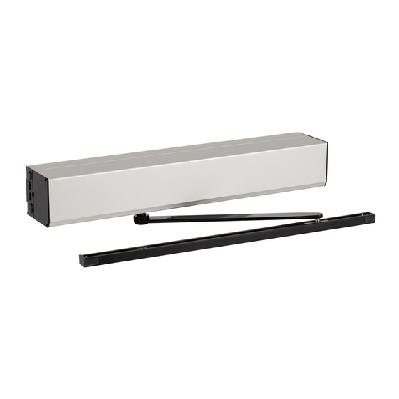
ASSA ABLOY SW100, standard cover (wall mounted) ASSA ABLOY SW100 is the standard operator. Pushing arm system shown. Measurement from hinge centerline to outgoing shaft is always 210 mm regardless if butt or pivot hinged systems. -
Page 17: Assa Abloy Sw100-Spec, Cover With Optional Length (Wall Mounted)
ASSA ABLOY SW100-SPEC, cover with optional length (wall mounted) The ASSA ABLOY SW100-SPEC carries a cover with optional length e.g. with the same width as the frame. The cover length L and the measurement R must be specified in the order. -
Page 18: Part Identification & Accessories
7 Part identification & Accessories Part identification & Accessories Primary Secondary Item No. Art. No. Description 331003498 Transmission unit 331003532 Control unit CU-ESD 331003554 EXU-SI (Kit to extend the security functions) - optional 331003557 EXU-SA (Kit to extend the safety functions) - optional 331700607 Mains contact 330000230... - Page 19 7 Part identification & Accessories Item No. Art. No. Description 331003508 Clock spring 1005088-en-22.0 Issue 2021-02-24...
-
Page 20: Arm System, Push
7 Part identification & Accessories Arm system, PUSH Art. No. 1007241BK/SI PUSH It is used if the operator is wall mounted on the opposite side compared with the opening direction and that the unit must be approved for fire applications. 7.1.1 PUSH-arm extensions Reveal = A... -
Page 21: Arm System, Pull-220
7 Part identification & Accessories Arm system, PULL-220 Art. No. 1011998BK/SI PULL-220 It is used if the operator is installed on the wall on the same side as the door swing and when the door is 450-700 mm wide. Reveal spacer: PULL / PULL-220 Art. -
Page 22: Drive Shaft Extension Kits
7 Part identification & Accessories Drive shaft extension kits 70 mm (2-3/4") 50 mm (2") 20 mm (3/4") Art. No. Art. No. Art. No. 173107BK/173107SI 173108BK/173108SI 173109BK/173109SI Lower adapter M8, used for 20 mm lower installation height. Art. No. 1007618 Issue 2021-02-24 1005088-en-22.0... -
Page 23: Control Switches
7 Part identification & Accessories Control switches 7.8.1 ON/OFF/HOLD open switch (will not operate electric lock) White Brown Green P/N: 1003582 Art. No. 1003582 Function Program Impulses from activation units connected to XIMP are forwarded into inner impulse (see page 44). -
Page 24: Sync Cable For Double Doors (Synchronizing Of 2 Operators)
7 Part identification & Accessories Sync cable for double doors (synchronizing of 2 operators) Note! Connect a cable between primary CU and secondary CU. Secondary Primary Primary Secondary Black Note! The connection/marking of the sync cable determines which of the operators is the primary and secondary. - Page 25 7 Part identification & Accessories Settings for double doors Settings on the Function Primary Secondary side side Common Program selection Opening time Closing time Hold open time Close / Continue to open when the door is obstructed PAG On/Off Level of Power assist (X)* Extended closing force (X)*...
-
Page 26: Extension Units
7 Part identification & Accessories 7.10 Extension units For installation see page 45. EXU-SI (kit for security functions) EXU-SA (kit for safety functions) Art. No. 1003554 Art. No. 1003557 0.5 s AIU (Audible warning signal) Art. No. 656083 ILL-01887 24 V DC 7.11 Battery backup unit Note! Disconnect mains when replacing battery. -
Page 27: Labels
Emergency break-out, DIN left door Art. No. 1001786 Activation by disabled people Click! Art. No. 1003963 Operator designed for disabled people Art. No. 1003964 Supervision of child Art. No. 1001695 ASSA ABLOY door sticker Art. No. 1700038 1005088-en-22.0 Issue 2021-02-24... -
Page 28: Pre-Installation
8 Pre-installation Pre-installation General tips/Safety concerns In all instances, where work is being done, the area is to be secured from ped- estrian traffic, and the main power removed to prevent injury. • Make sure that the power is off before installing. •... -
Page 29: Installation Examples
Brick wall Expansion-shell bolt, min. M6x85, UPAT PSEA B10/25, min. 50 mm from the underside * ASSA ABLOY Entrance Systems minimum recommended requirements. Building Codes may give different specifications. ** Thinner wall profiles (3-5 mm) must be reinforced with rivet nuts. -
Page 30: Tools Required
8 Pre-installation Tools required • Torx T10 • Metric Allen wrenches 2,5; 3; 4 and 6 mm • Flatblade screwdriver (potentiometer and terminal size) • Screwdriver (Philips size 2) • Nut driver, 5 mm • Carpenter’s level • Tape rule •... -
Page 31: Mechanical Installation
9 Mechanical installation Mechanical installation Note! Consider all power wire entry locations and signaling wires before preparing back plate. Operator with PUSH arm system PUSH C L 2 2 - 17 2 - 37 2 - 67 2 - 87 0 - 100 (305) 0−100 1005088-en-22.0... - Page 32 9 Mechanical installation Cont. "Operator with PUSH arm system" DIN Right PUSH DIN Right Cable inlet Ø C L 1 Issue 2021-02-24 1005088-en-22.0...
- Page 33 9 Mechanical installation Cont."Operator with PUSH arm system" PUSH C L 2 Operator should be attached using the top/centered bolt first, then follow pattern C L 1 1005088-en-22.0 Issue 2021-02-24...
- Page 34 9 Mechanical installation Cont."Operator with PUSH arm system" PUSH DIN Left DIN Left C L 1 Issue 2021-02-24 1005088-en-22.0...
- Page 35 9 Mechanical installation Cont."Operator with PUSH arm system" PUSH C L 1 C L 2 Operator should be attached using the top/centered bolt first, then fol- low pattern 1005088-en-22.0 Issue 2021-02-24...
- Page 36 9 Mechanical installation Cont."Operator with PUSH arm system" PUSH (2x) 90° 25 Nm Issue 2021-02-24 1005088-en-22.0...
-
Page 37: Operator With Pull Arm System
9 Mechanical installation Operator with PULL arm system PULL C L 2 40 x 60 -20 - 130 Note! Measurement Z must be reduced by 20 mm if lower adapter from kit 1007618 is used. 1005088-en-22.0 Issue 2021-02-24... - Page 38 9 Mechanical installation Cont. "Operator with PULL arm system" DIN Left PULL DIN Left C L 1 ILL-01592 Issue 2021-02-24 1005088-en-22.0...
- Page 39 9 Mechanical installation Cont. "Operator with PULL arm system" PULL C L 2 C L 2 C L 2 C L 1 Operator should be attached using the top/centered bolt first, then follow pattern 1005088-en-22.0 Issue 2021-02-24...
- Page 40 9 Mechanical installation Cont. "Operator with PULL arm system" DIN Right PULL DIN Right C L 1 ILL-01667 Issue 2021-02-24 1005088-en-22.0...
- Page 41 9 Mechanical installation Cont. "Operator with PULL arm system" C L 2 PULL C L 2 C L 1 C L 2 Operator should be attached using the top/centered bolt first, then follow pattern 1005088-en-22.0 Issue 2021-02-24...
- Page 42 9 Mechanical installation Cont. "Operator with PULL arm system" PULL 25 Nm Click Click Note! Do not change door stop for pull application. Issue 2021-02-24 1005088-en-22.0...
-
Page 43: Electrical Connection
10 Electrical connection Electrical connection Note! During any work with the electrical connections the mains must be disconnected. • Place the electric switch easily accessible from the operator. If a plug contact is used in the in- stallation the wall socket shall be placed easily accessible from the operator. •... -
Page 44: Control Units
10 Electrical connection 10.2 Control units 10.2.1 CU-ESD The CU-ESD can be equipped with extension units, EXU-SI and/or EXU-SA, depending on the functions required. See page 12 or 14. Encoder Lock kick switch Motor Synchronizing of double doors ON/OFF/HOLD open switch LEARN BUTTON 24 V DC LOUT... -
Page 45: Extension Units Exu-Si / Exu-Sa
10 Electrical connection 10.2.3 Extension units EXU-SI / EXU-SA Installation To extend the functions, the extension units can be mounted on top of the control unit CU-ESD, separately or combined. Torx T10 EXU-SA 5 mm nut driver EXU-SI Mains Tag strip long 2 pcs EXU short 1 pc EXU CU-ESD... -
Page 46: Extension Unit Exu-Si
10 Electrical connection 10.2.4 Extension unit EXU-SI Functions This extension unit has inputs for electro-mechanical lock, program selector, batteries, KILL function, OPEN/CLOSE, KEY opening and outer impulse. Battery backup unit +24 V DC OPEN Program selector EXIT Unlocked signal from lock KILL reset (see jumper below) KRST KILL impulse... -
Page 47: Extension Unit Exu-Sa
10 Electrical connection 10.2.5 Extension unit EXU-SA This extension unit has inputs for door mounted sensors, which can give presence impulse on approach side and/or presence detection on swing path side. Relay output for error indication or door indication is also integ- rated. -
Page 48: Sensor Cable Inlet
10 Electrical connection 10.3 Sensor cable inlet Art. No.: 1007567 Alt. 1 Alt. 1 ø 3.7 Alt. 2 Alt. 2 Art. No.: 1015368BK/SI Art. No.: 1015368 Issue 2021-02-24 1005088-en-22.0... -
Page 49: Start-Up
11 Start-up Start-up The spring pre-tension is factory set to 210° and is normally not necessary to adjust. If adjustment has to be carried out, see page 11.1 Adjusting the door stop a Close the door. b Turn the potentiometer SPTE to 0° (if not already on 0°). SPTE CU-ESD 0°... -
Page 50: Micro Switch
11 Start-up Close the door by turning the potentiometer SPTE to 0° and let the door close. Note! Impulses are not accepted if SPTE is more than 0°. SPTE 0° Micro switch Lock kick cam Stop block Fine-adjustment screw Door stop arm 11.2 Micro switch Control the lock kick by turning the lock kick cam (2) when power is off. -
Page 51: Auto-Learn Automatically Sets Back And Latch Check (Recommended)
11 Start-up 11.3 Auto-learn automatically sets back and latch check (recommended) This learning is performed by pushing the LEARN BUTTON (LRN). • Before the learning procedure starts, make sure that the door has been properly closed i.e., not by force. •... -
Page 52: General Adjustment
11 Start-up 11.4 General adjustment a Set the hold open time with the potentiometer on the control unit. b Adjust the opening speed (OPSP). Turning clockwise increases the speed. c Adjust the closing speed (CLSP). Turning counter-clockwise decreases the speed. See the “Guide for installers of Powered Pedestrian Swing Doors”, Product Risk Assessment document PRA-0006, for calculation of speed. -
Page 53: Connection Of Activation Units And Accessories
When sensors are used in order to avoid contact with the door leaf it is required that the presence detect sensor and the presence impulse sensor fulfills Performance Level = d according to EN ISO 13849-1. These sensors shall also be monitored (tested) by ASSA ABLOY SW100 door operator. Configue sensor SP33-M:... -
Page 54: Cover
When properly installed and adjusted, attach the product label, which includes the CE mark on the right side of the lower part of the operator cover (see illustration). Apply the ASSA ABLOY logotype to the cover see illustration. Only for SE: Apply the SITAC label next to the product label - see illustration. -
Page 55: Cover Piece Kit
12 Cover 12.2 Cover piece kit Single door CL-719.5 Double door CL-1433 1005088-en-22.0 Issue 2021-02-24... -
Page 56: Signage
Product label: Mandatory Emergency break-out: Mandatory, if approved for escape route. ASSA ABLOY Entrance Systems door sticker: Mandatory, if applicable to highlight the presence of the glass (applied to all glass sections that are moving). Supervision of child (applied to both sides of the door): Mandatory according to national regulations. Recommended, if the risk analysis shows use by children. -
Page 57: Advanced Settings
14 Advanced settings Advanced settings 14.1 Learn with advanced setting of “back- and latch-check” See the prerequisites for performing a “learn” under the heading Auto-learn automatically sets back and latch check (recommended) on page a Push the button once or twice as for auto-setting. b Stop the door at required back-check. -
Page 58: Changing Group Of Parameters (Level 2)
14 Advanced settings 14.3 Changing group of parameters (Level 2) a Disconnect batteries if any. b Disconnect the mains. c Press the LEARN BUTTON (LRN) and keep it depressed. d Connect the mains. e Watch the ERROR LED. Release the LEARN BUTTON after 2 flashes (LED is out). The ERROR LED flashes a number of short flashes that corresponds to the parameter group number (see table). -
Page 59: Classification (Level 3)
14 Advanced settings 14.4 Classification (Level 3) a Disconnect batteries if any. b Disconnect the mains. c Press the LEARN BUTTON (LRN) and keep it depressed. d Connect the mains. e Watch the ERROR LED. Release the LEARN BUTTON after 3 flashes (LED is out). g Identify the current classification The ERROR LED flashes an amount of short flashes that correspond to the classification number. -
Page 60: O Verhead Presence Detection (Opd) Monitoring (Level 4)
14 Advanced settings 14.5 O verhead Presence Detection (OPD) Monitoring (Level 4) a Disconnect batteries if any. b Disconnect the mains. c Press the LEARN BUTTON (LRN) and keep it depressed. d Connect the mains. e Watch the ERROR LED. Release the LEARN BUTTON after 4 flashes (LED is out). -
Page 61: Lock Kick (Level 5)
14 Advanced settings 14.6 Lock kick (Level 5) a Disconnect batteries if any. b Disconnect the mains. c Press the LEARN BUTTON (LRN) and keep it depressed. d Connect the mains. e Watch the ERROR LED. Release the LEARN BUTTON after 5 flashes (LED is out). g Identify the current lock kick status The ERROR LED flashes an amount of short flashes that correspond to the status number. -
Page 62: Reducing / Increasing The "Spring Pre-Tension" (Spte)
15 Reducing / Increasing the “Spring pre-tension” (SPTE) Reducing / Increasing the “Spring pre-tension” (SPTE) The spring pre-tension is factory set to 210° and is normally not necessary to adjust. If adjustment has to be carried out see below. a Loosen the door stop arm. Remove if fitted on the topside, slide down if fitted on the bottom. b Turn the potentiometer for spring pre-tension (SPTE) clockwise until the door opens to 45°. -
Page 63: Installation And Adjustments
16 Installation and adjustments Installation and adjustments 16.1 Complementary Safety Devices Swing Doors If there is any risk for finger jam, add finger protection strip at the hinge side for internal doors, article No. 833334 or add finger protection roll for external doors, article No. 833333. 16.2 Swing Doors Opening and Closing Time Adjust, as a minimum, the operator's opening and closing time according to the diagram below. -
Page 64: Diagrams For Door Weight
16 Installation and adjustments 16.3 Diagrams for Door weight a Measure the door width (DW) and the door height (DH) in metres for one door leaf only. b Calculate the area DW x DH. c Select diagram for your type of door and the actual glass thickness. Find the weight. Example: Aluminium door with measurement DW = 1.5 m, DH = 2 m and glass thickness 12 mm. -
Page 65: Troubleshooting
17 Troubleshooting Troubleshooting Fault Possible reasons why Remedies/Explanations The door does not open Control switch is set to OFF Change the setting of the control switch The motor does not start Mains are missing Check the mains switch Activation unit does not function Strap impulse inputs Presence detection is activated Check that there are no objects in the detec-... -
Page 66: Error Indication
17 Troubleshooting 17.1 Error indication • During normal operation the ERROR LED on the control unit is illuminated. • An extinguished LED indicates that there is no mains. • A flashing light on the LED indicates that the operator is out of function (see table below). •... -
Page 67: Service / Maintenance
Service / Maintenance Regular inspections shall be made according to national regulations and product documentation by an ASSA ABLOY Entrance Systems-trained and qualified technician. The number of service occa- sions should be in accordance with national requirements and product documentation. This is especially important when the installation concerns a fire-approved door or a door with an emer- gency opening function. - Page 68 Building on the long-term success of the Besam, Crawford, Albany and Megadoor brands, we offer our solutions under the ASSA ABLOY brand. Our products and services are dedicated to satisfying end-user needs for safe, secure, convenient and sustainable operations.
Need help?
Do you have a question about the SW100 and is the answer not in the manual?
Questions and answers
Where is the control switch on the SW100 door operator, doors won't close