Table of Contents
Advertisement
Quick Links
Advertisement
Table of Contents

Related Manuals for Chroma 62000P Series


Summary of Contents for Chroma 62000P Series
- Page 2 Programmable DC Power Supply 62000P Series Operating & Programming Manual Version 1.0 August 2005...
- Page 3 The information in this document is subject to change without notice. Chroma ATE INC. makes no warranty of any kind with regard to this manual, including, but not limited to, the implied warranties of merchantability and fitness for a particular purpose.
- Page 4 Any recommendations made by Chroma for use of its products are based upon tests believed to be reliable, but Chroma makes no warranty of the results to be obtained. This warranty is in lieu of all other warranties, expressed or implied, and no representative or person is authorized to represent or assume for Chroma any liability in connection with the sale of our products other than set forth herein.
- Page 5 Failure to comply with these precautions or specific WARNINGS given elsewhere in this manual will violate safety standards of design, manufacture, and intended use of the instrument. Chroma assumes no liability for the customer’s failure to comply with these requirements.
- Page 6 SAFETY SYMBOLS DANGER - High voltage. Explanation: To avoid injury, death of personnel, or damage to the instrument, the operator must refer to an explanation in the instruction manual. Protective grounding terminal: To protect against electrical shock in case of a fault.
- Page 7 Revision History The following lists the additions, deletions and modifications in this manual at each revision. Date Version Revised Sections Aug. 2005 1.0 Complete this manual...
-
Page 8: Table Of Contents
Programmable DC Power Supply 62000P Series Operating & Programming Manual Table of Contents Overview ........................1-1 Introduction ......................1-1 System Functions ....................1-1 1.2.1 Operation Mode....................1-1 1.2.2 Protection ......................1-1 1.2.3 Output/Indication ....................1-1 1.2.4 Input Control Signals ..................1-2 1.2.5 Measuring & Editing..................1-2 Specifications ......................1-2 1.3.1... - Page 9 Programmable DC Power Supply 62000P Series Operating & Programming Manual 3.3.2.2 CURRENT LIMIT SETTING ..............3-13 3.3.2.3 VOLTAGE SLEW RATE.................3-14 3.3.2.4 CURRENT SLEW RATE SETTING ............3-15 3.3.2.5 TTL Option ....................3-16 3.3.3 SERIES/PARALLEL ..................3-17 3.3.3.1 Assembling Series/Parallel Communication Interface......3-18 3.3.3.2 Setting Series/Parallel Operation Mode ............3-20 3.3.3.3...
- Page 10 Programmable DC Power Supply 62000P Series Operating & Programming Manual 4.3.2 Program Main Page Description ..............4-16 Remote Operation......................5-1 Overview .........................5-1 5.1.1 Setting GPIB Address & RS-232C Parameters..........5-1 5.1.2 Connecting RS-232C..................5-1 GPIB Function of 62012P Series ................5-2 Introduction to Programming ..................5-2 5.3.1...
-
Page 12: Overview
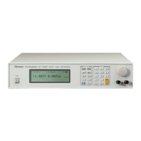
Overview Overview Introduction Chroma 62000P Series are constant DC Power Supplies that can provide stable DC output and accurate measurement for voltage and current. The features of 62000P Series DC Power Supply are: (1) Voltage mode with two loops control able to provide stable and quick responded output, also to set the slew rate of output voltage and current. -
Page 13: Input Control Signals
(2) 10 programs and 100 sequences to edit voltage/current waveform output. Specifications The operating specifications of 62000P Series DC Power Supply are listed below. Besides the specifications specified particularly, all specifications are tested following the standard test procedure of Chroma (test condition: 25 ± 5°C and under resistance load). - Page 14 Overview Model 62006P-100-25 62012P-30-160 62012P-80-60 62012P-100-50 62012P-600-8 Output Ratings Output Voltage 0-100V 0-30V 0-80V 0-100V 0-600V Output Current 0-25A 0-160A 0-60A 0-50A 0-8A Output Power 600W 1200W 1200W 1200W 1200W Line Regulation Voltage 0.01%+6mV 0.01%+2mV 0.01%+8mV 0.01%+10mV 0.01%+18mV Current 0.01%+5mA 0.01%+25mA 0.01%+10mA 0.01%+12mA 0.03%+20mA Load Regulation Voltage...
-
Page 15: Other Specifications
Programmable DC Power Supply 62000P Series Operating & Programming Manual NOTE Minimum output voltage <0.15% of rate voltage. Minimum output current <0.2% of rate current. 95-250Vac with rated load. For 0-100% load step with nominal line voltage. Verified by scope with BNC cable and 50 (Ohm) termination. -
Page 16: Function Keys
Overview Fault Output Signal Indicate if there is a fault/protection occurred, Active Low. By RS-485 Series & Parallel operation function with Master / Slave control interface Voltage limit @ Series Mode. (Floating output) 1200 Volt Voltage limit @ Series Mode (Refer to Ground) 240 Volt Number of DC Power Supplies allowed @ master / slave control mode Auto Sequencing Programmable Function... - Page 17 Programmable DC Power Supply 62000P Series Operating & Programming Manual Item Symbol Description DISPLAY: LCD Display: it shows the output settings and measured result. Numeric and Decimal Point: Users can use the numeric keys and the decimal point key to ●...
-
Page 18: Rear Panel
Overview Item Symbol Description Main Power Switch: It switches the power on or off. Rack Bracket:(Option) Use the left (right) bracket to fit the Power Supply on Rack. Table 1-1 Description of Front Panel 1.4.2 Rear Panel 95V-250V~ 47-63Hz / 1700VA Figure 1-2 Rear Panel Item Name... -
Page 20: Installation
Installation Checking the Package (1) Check if there is any damage or any missing accessories after unpacking it. (2) Should any damage it found, contact “Chroma RMA” immediately to request return shipment. The machine package is shown as below. Figure 2-1 NOTICE Please keep all of the packing materials in case the device has to be returned for repair. -
Page 21: Preparation For Use
Programmable DC Power Supply 62000P Series Operating & Programming Manual LCD front panel. For internal cleaning, use a low-pressure air gun the dust inside or send it back to our agent for cleaning. Preparation for Use (1) Be sure the Power Supply is connected to the AC line input that meets the specification. -
Page 22: Output Connection
Figure 2-2 Output Connection 62000P Series DC Power Supply has two output connectors, one is located at the left on the rear panel while the other one is located at the right on the front panel. The load is connected to “+” and “-” output terminal. -
Page 23: Rear Panel Output
2-4 for connection. Figure 2-4 CAUTION For safety reason, do not exceed rated current (different from 62000P Series) for the output current to avoid any danger. NOTICE The maximum current for front panel output differs from 62000P Series models. The... -
Page 24: Specification Of Connecting Wire
Installation The maximun output Model current (A) 62012P-80-60 62012P-100-50 62012P-600-8 62012P-30-160 62006P-100-25 2.4.3 Specification of Connecting Wire The maximum output inductance of connecting wire to the source is 2µH (it is the total inductance of two wires after twisted or processed otherwise including self inductance and mutual inductance). -
Page 25: Disconnecting Remote Sensing Wire
Programmable DC Power Supply 62000P Series Operating & Programming Manual Figure 2-5 2.5.2 Disconnecting Remote Sensing Wire If the remote sensing wire is disconnected (means the two cables are open), it still works however the error range will be wider. The voltage measured from the output terminal is about 2% larger than the set value;... -
Page 26: Reverse Connection Of Remote Sensing Wire Polarity
Installation 2.5.3 Reverse Connection of Remote Sensing Wire Polarity The polarity of remote sensing wire must be connected correctly, that is the “+” terminal is connected to the “+” of output terminal or to the connecting wire of the terminal, while the “-”... -
Page 27: Power On Procedure
Programmable DC Power Supply 62000P Series Operating & Programming Manual Power On Procedure Plug in the power cord and turn on the power switch on front panel. The DC Power Supply will run a series of self-tests. The LCD on front panel will light up and show as below: T EST . -
Page 28: I/O Connector (Option)
Installation V _ S E T = 0 . 0 V I _ SE T = 0 . 0 A O F F 0 0 . 0 0 V 0 0 . 0 0 A 0 . 0 Figure 2-11 WARNING Users can diagnose if there is any NG during self-test at power-on. -
Page 30: Manual Operation
Manual Operation Manual Operation Introduction DC Power Supply can be operated manually or remotely via GPIB controller or RS-232C or APG interface which is described in Chapter 5 and section 3.3.1.3. The manual operation for using the front panel keyboard or rotary knob to input the data is described in this chapter. NOTICE If the operation mode is not saved before users power the instrument off, the operation mode is manual (default) when power it on next time. -
Page 31: Setting Configuration
Programmable DC Power Supply 62000P Series Operating & Programming Manual Following is the way to set the current (CC MODE): Press “ CURRENT ” and the rest settings are same as voltage as Figure 3-2 shows. (Be noted that in order to remain the output in CC mode the load current setting must be larger than the current, otherwise the output current will not equal to the set current.) - Page 32 Manual Operation C H O I C E = S Y S T E M S E T U P [ C O N F I G ] 1 . S Y S T E M S E T U P 5 .
-
Page 33: System Setup
Programmable DC Power Supply 62000P Series Operating & Programming Manual CONFIG PAGE GPIB ADDR RS-232 BAUDRATE 1. SYSTEM SETUP BACKLIGHT TTL VALUE BUZZER POWER ON STATUS V LIMIT I LIMIT V SLEW RATE 2. OUTPUT SETUP I SLEW RATE TTL VALUE MASTER &... -
Page 34: Gpib Address
Manual Operation [ S Y S T E M S E T U P ] G P I B A D D R R S - 2 3 2 B A U D R A T E = 9 6 0 0 A P G N O N E B A C K L I G H T... -
Page 35: Apg
Programmable DC Power Supply 62000P Series Operating & Programming Manual 3.3.1.3 APG Analog Programming interface (APG) uses analog signal to control the output. This option decides whether or which APG control function is in use, and no matter what option is selected the measurement functions are available. - Page 36 Manual Operation Press “ EXIT ” to return to MAIN PAGE. NOTICE APG has two reference voltage level: V_ref(V)=5 / 10 a. When selecting Vref=5V it means the DC Power Supply’s output 0V/0A~80V/60A will map to 0~5V (programming or measurement) as Figure 3-8(a) shows. b.
-
Page 37: Backlight
Programmable DC Power Supply 62000P Series Operating & Programming Manual +12VA APIGND V SET I SET MEAS. MEAS. − − Sensing Sensing Figure 3-10 Following lists the definition of each pin: Auxiliary power Vcc: This pin outputs a +12Vdc power with maximum output current 10mA (output port). -
Page 38: Buzzer
Manual Operation [ S Y S T E M S E T U P ] G P I B A D D R R S - 2 3 2 B A U D R A T E = 9 6 0 0 A P G V r e f ( V ) =5 B A C K L I G H T... -
Page 39: Power On Status
Programmable DC Power Supply 62000P Series Operating & Programming Manual Use the numeric ( ) keys or “Rotary”( ) knob to select “ON” or “OFF” mode. ENTER Press “ ” to confirm. EXIT Press “ ” to return to MAIN PAGE. -
Page 40: Output Setup
Manual Operation Ex.: In Figure 3-14, the voltage setting is 80.00V, current setting is 15.00A and output setting is ON. When it powers on again, the instrument will remain the previous state by setting the voltage to 80.00V, current to 15.00A and output to ON. V _ S E T = 8 0 . -
Page 41: Voltage Limit Setting
Programmable DC Power Supply 62000P Series Operating & Programming Manual [ O U T P U T S E T U P ] L I M I T : M A X = 8 0 . 0 0 V M I N = 0 0 0 . -
Page 42: Current Limit Setting
Manual Operation V _ S E T = 8 0 . 0 0 V I _ S E T = 1 5 . 0 0 A 8 0 . 0 0 V 1 2 . 0 0 A 9 6 0 . 0 W V RAGNE = [V LIMIT MIN]V~[V LIMIT MAX]V Figure 3-18 ENTER... -
Page 43: Voltage Slew Rate
Programmable DC Power Supply 62000P Series Operating & Programming Manual V _ S E T = 8 0 . 0 0 V I _ S E T = 1 5 . 0 0 A 8 0 . 0 0 V 1 2 . -
Page 44: Current Slew Rate Setting
Manual Operation ∆ ∆ ΔV ΔT Time(mS) Figure 3-22 ENTER Press “ ” to confirm. EXIT Press “ ” to return to MAIN PAGE. NOTICE Minimum transient time ( Δ T) = 0.5 ms 。 3.3.2.4 CURRENT SLEW RATE SETTING Use “... -
Page 45: Ttl Option
Programmable DC Power Supply 62000P Series Operating & Programming Manual 3.3.2.5 TTL Option When the DC Power Supply is outputting, its SYSTEM STATUS connector on the rear panel offers 8 BIT digital signals for other purpose use. The TTL VALUE range is from 0 to 255 , in addition the system will convert it by binary automatically for easy identification. -
Page 46: Series/Parallel
3.3.3 SERIES/PARALLEL 62000P Series DC Power Supplies are able to operate in series or parallel. Take example by 62012P-80-60, the voltage is up to 400V if connecting 5 sets in series, and the current is up to 300A if connecting 5 sets in parallel. -
Page 47: Assembling Series/Parallel Communication Interface
Programmable DC Power Supply 62000P Series Operating & Programming Manual 3.3.3.1 Assembling Series/Parallel Communication Interface To operate the Power Supply in series, connect the RS-485 connectors on the rear panel as Figure 3-26 shows. R S 485 C U R R EN T... - Page 48 Power Supply and so forth. Then connect the output terminal of the last Power Supply back to the input terminal of the first as Figure 3-27 shows in dot line. Be sure to use the CURRENT SHARING communication cable provided by CHROMA. The CURRENT SHARING communication cable must be well connected when in parallel operation, or it may cause the DC Power Supply to run abnormally or poor result in CURRENT SHARING.
-
Page 49: Setting Series/Parallel Operation Mode
Programmable DC Power Supply 62000P Series Operating & Programming Manual 3.3.3.2 Setting Series/Parallel Operation Mode 1. In Config Setup page, press “ ”. ENTER 2. Press “ ” to enter into PARALLEL /SERIES option as Figure 3-28 shows. [ S E R I E S / P A R A L L E L ] M A S T E R &... - Page 50 Figure 3-29 NOTICE For 62000P Series to be operated in series/parallel mode, it is necessary to set SLAVE first and MASTER last, or it will show communication error and unable to work. If the setting procedure is reversed by setting the MASTER (MASTER OR SLAVE MASTER) first, when pressing “...
- Page 51 Programmable DC Power Supply 62000P Series Operating & Programming Manual 3.3.3.3.1 MASTER If MASTER OR SLAVE is set to MASTER, a MASTER setup window will prompt for PARALLEL OR SERIES and NUM. OF SLAVE selections. See the description of PARALLEL OR SERIES in section 3.3.3.3.2 and NUM. OF SLAVE in section 3.3.3.3.3.
- Page 52 Manual Operation [ S E R I E S / P A R A L L E L ] Y E S M A S T E R & S L A V E C O N T R O L = M A S T E R O R S L A V E M A S T E R...
- Page 53 Programmable DC Power Supply 62000P Series Operating & Programming Manual NOTICE Take example by 62012P-80-60: If there are 5 sets connected in parallel and 80V/300A is set, the setting of each set is 80V/60A and the total output will be 80V/300A.
- Page 54 Manual Operation [ SE R I E S / P A R A L L E L ] Y E S M A S T E R & S L A V E C O N T R O L = M A S T E R O R S L A V E S L A V E...
-
Page 55: Setting Series Parameters
Programmable DC Power Supply 62000P Series Operating & Programming Manual S L A V E 1 Figure 3-37 3.3.3.4 Setting Series Parameters NOTICE Series/Parallel setting procedure: First set the SLAVES. Last set the MASTER. When the software communication and hardware settings for series are completed, the settings of following windows are introduced in the sections underneath - (1) MAIN PAGE, (2) SYSTEM SETUP, (3) OUTPUT SETUP and (4) PROTECTION. - Page 56 Manual Operation 3.3.3.4.2 Setting SYSTEM SETUP for Series The option POWER ON STATUS in SYSTEM SETUP must set to USER DEFINIITION when connected in series along with the output voltage. The voltage set increases following the number connected in series and for easy identification it is indicated by Σ V as Figure 3-39 shows.
-
Page 57: Setting Parallel Parameters
Programmable DC Power Supply 62000P Series Operating & Programming Manual [ P R O T E C T I O N ] O V P 4 4 0 . 0 V Σ O C P 6 3 . 0 A O P P 6 0 0 0 . - Page 58 Manual Operation 3.3.3.5.2 Setting SYSTEM SETUP for Parallel The option POWER ON STATUS in SYSTEM SETUP must set to USER DEFINIITION when connected in parallel along with the output current. The current set increases following the number connected in parallel and for easy identification it is indicated by Σ I as Figure 3-43 shows.
-
Page 59: Setting Procedure For Apg In Series Or Parallel
Programmable DC Power Supply 62000P Series Operating & Programming Manual [ P R O T E C T I O N ] O V P 8 8 . 0 V O C P 6 3 . 0 A Σ O P P 1 2 6 0 . - Page 60 Manual Operation 400V/60A 400V/60A APG INPUT 5V/5V APG INPUT 10V/10V Figure 3-47 3.3.3.6.2 Parallel Setting To connect 5 62012P-80-60 DC Power Supplies in parallel for operation and set the APG option to APG = V &I and Vref(V) = 5, the MAIN PAGE of MASTER will show as Figure 3-48.
-
Page 61: Display
Programmable DC Power Supply 62000P Series Operating & Programming Manual 80V/300A 80V/300A APG INPUT 5V/5V APG INPUT 10V/10V Figure 3-49 3.3.4 DISPLAY DISPLAY setting has two options: (1) DISPLAY SELECTION and (2) READING AVERAGE TIMES. 3.3.4.1 DISPLAY SELECTION The setting of DISPLAY is to show the internal settings on the last line of MAIN PAGE for easy identification without entering the setting page. - Page 62 Manual Operation [ D I S P L A Y S E L E C T I O N ] D I S P L A Y S E L E C T I ON = N O N E R E A D I N G A V E R A G E T I ME S = 1 Figure 3-50 Use the numeric (...
- Page 63 Programmable DC Power Supply 62000P Series Operating & Programming Manual V _ S E T = 2 0 . 0 0 V I _ S E T = 6 0 . 0 0 A O F F 0 0 . 0 0 V 0 0 .
-
Page 64: Reading Average Times
3.3.5 PROTECTION Chroma 62000P Series DC Power Supplies have complete protection functions divided in two classes. The first type protection includes over voltage, over current, over power and FOLDBACK; while the second type protection includes over temperature, fan failure and over/under input voltage. -
Page 65: Ovp Protection
Programmable DC Power Supply 62000P Series Operating & Programming Manual [ P R O T E C T I O N ] O V P 8 8 . 0 V O C P 6 3 . 0 A O P P 1 2 6 0 . -
Page 66: Ocp Protection
Manual Operation NOTICE The table below is the voltage range of OVP. Model Min. OVP (V) Max. OVP (V) 62000P-xx-xx 1.10 x Vo_SET 1.10 x Vo_MAX Table 3-4 OVP Range When 0 is set for the OVP, it means the function is disabled. When OVP occurs the main page will prompt a protection message as shown below: V _ S E T = 8 0 . -
Page 67: Opp Protection
Programmable DC Power Supply 62000P Series Operating & Programming Manual EXIT Press “ ” to return to MAIN PAGE. This function sets the protection point for Over Current. Once the output current exceeds the range, it will turn off the output that is OUTPUT = OFF to protect the unit under test. -
Page 68: Foldback
Manual Operation Use the numeric ( ) keys or “Rotary” ( ) knob to set the value. ENTER Press “ ” to confirm. EXIT Press “ ” to return to MAIN PAGE. This function sets the protection point for Over Power. Once the output power exceeds the range, it will turn off the output that is OUTPUT = OFF to protect the unit under test. - Page 69 Programmable DC Power Supply 62000P Series Operating & Programming Manual [ P R O T E C T I O N ] O V P 8 8 . 0 V O C P 6 3 . 0 A O P P 1 2 6 0 .
- Page 70 Manual Operation V _ S E T = 8 0 . 0 0 V I _ S E T = 1 5 . 0 0 A O F F 0 0 . 0 0 V 0 0 . 0 0 A 0 .
-
Page 71: Otp
Programmable DC Power Supply 62000P Series Operating & Programming Manual 3.3.5.5 OTP The OTP protection will activate when the internal temperature reaches the high limit and the output will be turned off that is OUTPUT = OFF for protection. When OTP occurs the main page will prompt a protection message as shown below: V _ S E T = 8 0 . -
Page 72: Sense Fault Protection
Manual Operation NOTICE The table below lists the typical value of AC FAULT for 62000P Series: Less than (Vac) More than (Vac) Input Voltage 85.5 Table 3-7 AC FAULT Range Once the AC FAULT is activated the output is turned off that is OUTPUT = OFF and won’t be turned on that is OUTPUT = ON until the input voltage is within SPEC. -
Page 73: Fanlock Protection
Programmable DC Power Supply 62000P Series Operating & Programming Manual 3.3.5.8 FANLOCK Protection Fans are built-in inside the DC Power Supply to ventilate the heat generated by components. If one of the fans is fail (not running), FANLOCK protection will occur and the output will turn off that is OUTPUT = OFF for protection. -
Page 74: Factory Setting
Manual Operation V _ S E T = 8 0 . 0 0 V I _ S E T = 1 5 . 0 0 A O F F 0 0 . 0 0 V 0 0 . 0 0 A 0 . -
Page 75: Calibration
3.3.7 CALIBRATION Chroma 62000P Series DC Power Supplies have 4 calibration functions: (1) VOLTAGE: the actual voltage output (CV mode) and its measurement accuracy, (2) CURRENT: the actual current out (CC mode) and its measurement accuracy, (3) APG VOLTAGE: the actual... -
Page 76: Voltage Output & Measurement Calibration
Manual Operation ENTER Enter the password and press “ ” to confirm. The screen will display 4 calibration options as Figure 3-74 shows. The calibration steps are described from section 3.3.7.1 to 3.3.7.5. To abort CALIBRATION, press “ EXIT ” to return to MAIN PAGE. C H O I C E = V O L T A G E [ C A L I B R A T I O N ] 1 . - Page 77 Programmable DC Power Supply 62000P Series Operating & Programming Manual 3.3.7.1.3 Calibration Procedure (Example: Model 62012P-80-60) (1) Enter into the page of Figure 3-74. (2) In CALIBRATION page, press “ ” or turn “Rotary” ( ) knob to set CHOICE=1.
- Page 78 Manual Operation ENTER Enter the voltage measured by DVM (4 digits after decimal point) and press “ ” to confirm. (8) Press “ ” again to do the high voltage range calibration for its second point, the instrument will set the output voltage to 70.00V and the cursor is stopped at position [2] as Figure 3-79 shows.
-
Page 79: Current Measurement Calibration
Programmable DC Power Supply 62000P Series Operating & Programming Manual It is necessary to remove the output load when performing voltage calibration. The LCD panel will show the text as Figure 3-77 and once no load is confirmed for the output, ENTER press “... - Page 80 Manual Operation [ C U R R E N T M E A S C A L I B R A T I O N ] R E M O V E A L L L O A D I N G F R O M O U T P U T T E R M I N A L P R E S S [ E N T E R ] W H E N R E A DY...
- Page 81 Programmable DC Power Supply 62000P Series Operating & Programming Manual After the low current range was calibrated, it is important to turn the loading of Electronic Load off reconnect the DC Power Supply to current shunt whose rating is closest to but still cover 20A. For Prodigit 7530, use 20A shunt directly.
-
Page 82: Current Output (Prog.) Calibration
Manual Operation 13. Press “ ” to return to MAIN PAGE. EXIT Improper shunt range selection may cause damage to the current shunt. NOTICE The calibration point may be different for other models (non 62012P-80-60), please operate it following the instructions displayed. 3.3.7.3 Current Output (PROG.) Calibration 3.3.7.3.1 Hardware Requirements Device... - Page 83 Programmable DC Power Supply 62000P Series Operating & Programming Manual [ C U R R E N T S E T T I N G C A L I B R A T I O N ] S H O R T O U T P U T...
- Page 84 Manual Operation (5) Now the DC Power Supply will be set to off again and a message will be popped up to remind user to reconnect to proper current shunt range. Set current shunt whose rating is closest to but still cover 10A. For Prodigit 7530, use 20A shunt directly. [ C U R R E N T S E T T I N G C A L I B R A T I O N ] S H O R T O U T P U T...
- Page 85 Programmable DC Power Supply 62000P Series Operating & Programming Manual [ C U R R E N T S E T T I N G C A L I B R A T I O N ] S H O R T...
- Page 86 Manual Operation (10) Press ENTER will perform 50A calibration. The system will set the output current to 50.00A automatically and the cursor will stop at position [4] as Figure 3-94 shows. Input the current (4 digits after decimal point) read by Current Shunt (DVM) and press ENTER “...
-
Page 87: Apg Voltage Calibration
Programmable DC Power Supply 62000P Series Operating & Programming Manual 3.3.7.4 APG Voltage Calibration 3.3.7.4.1 Hardware Requirements Device Suggest Model or Capacity HP 34401A or equivalent DVM DC Power Supply Any DC Power Supply or DC signal source that can output 10Vdc and drive 100mA. - Page 88 Manual Operation NOTICE When entering into the CALILBRATION page, be sure to check the interface connection ENTER on the rear panel is correct and then press “ ” to start calibration. If Agilent 34401 is used, the DVM1 and DVM2 can be connected to the front and rear measurement input terminal respectively.
-
Page 89: Apg Current Calibration
Programmable DC Power Supply 62000P Series Operating & Programming Manual [ A P G V O L T A G E C A L I B R A T I O N ] C H E C K A P G C O N N E C T I ON A N D P R E S S [ E N T E R ] ( M E A S . - Page 90 Manual Operation 3.3.7.5.2 SETUP +12VA APIGND V SET I SET MEAS. MEAS. − − − DC Power DVM1 DVM2 Supply Figure 3-100 3.3.7.5.3 Calibration Procedure (Example: Model 62012P-80-60) (1) In CALIBRATION page, press “ ” or turn “Rotary” ( ) knob to set CHOICE = 4. ENTER (2) Press “...
- Page 91 Programmable DC Power Supply 62000P Series Operating & Programming Manual [ A P G C U R R E N T C A L I B R A T I O N ] C H E C K A P G C O N N E C T I O N...
- Page 92 Manual Operation NOTICE The calibration point may be different for other models (non 62012P-80-60), please operate it following the instructions displayed. 3-63...
-
Page 94: Program Sequence
Program Sequence Program Sequence 62012P-80-60 allows users to program the sequence for output. There are 10 Programs with 10 Sequences in one Program that total 100 sequences are available for editing. Each sequence can be edited with voltage setting, voltage slew rate, current setting, current slew rate, running time and trigger type. -
Page 95: Description Of Program Settings
Programmable DC Power Supply 62000P Series Operating & Programming Manual [ P R O G R A M ] P R O G N O . P R O G C H A I N N O . = R U N... -
Page 96: Setting Prog Chain No
Program Sequence Use the numeric ( ) keys or “Rotary” ( ) knob to set the value. ENTER Press “ ” to confirm. EXIT Press “ ” to return to MAIN PAGE. [ P R O G R A M ] ) 1 ( P R O G N O . - Page 97 Programmable DC Power Supply 62000P Series Operating & Programming Manual A1: Execution steps: (1) When all PROG #1 SEQUENCES are done, skip PROG #2 and jump to PROG (2) When all PROG #3 SEQUENCES are done, jump to PROG #4...
- Page 98 Program Sequence START PROG #1 PROG CHAIN NO = 1 SEQ 1_1 ~ SEQ 1_10 Figure 4-5 Ex.3: Use multiple PROGRAMS to form an infinite loop Set PROG #1 to PROG CHAIN NO.=3, RUN COUNT=1 PROG #3 to PROG CHAIN NO.=4, RUN COUNT=1 PROG #4 to PROG CHAIN NO.=6, RUN COUNT=1 PROG #6 to PROG CHAIN NO.=1, RUN COUNT=1 The program execution flow is listed as Figure 4-6 shows.
-
Page 99: Setting Run Count
Programmable DC Power Supply 62000P Series Operating & Programming Manual START PROG #1 PROG #6 PROG CHAIN NO = 3 PROG CHAIN NO = 0 SEQ 1_1 ~ SEQ 1_10 SEQ 6_1 ~ SEQ 6_10 PROG #2 PROG #7 PROG CHAIN NO = 0... -
Page 100: Setting Clear Sequence
Program Sequence RUN COUNT TIMES 15000 Table 4-1 Ex. 4: Set RUN COUNT for a PROGRAM Set PROG #1 to PROG CHAIN NO.=3, RUN COUNT=2. PROG #3 to PROG CHAIN NO.=0, RUN COUNT=3. The program execution flow of RUN COUNT is listed as Figure 4-7 shows. A4: Execution steps: (1) When all PROG #1 SEQUENCES are done, return to PROG #1. -
Page 101: Setting Sequence
Programmable DC Power Supply 62000P Series Operating & Programming Manual Use the numeric ( ) keys or “Rotary” ( ) knob to set the value. ENTER Press “ ” to confirm. EXIT Press “ ” to return to MAIN PAGE. -
Page 102: Setting Sequence Number
Program Sequence ENTER Press “ ” to confirm. EXIT Press “ ” to return to Program PAGE (Figure 4-1). 4.2.1 Setting Sequence Number Use “ ”, “ ” keys to move the cursor to the column to be set as Figure 4-9 (1) shows. - Page 103 Programmable DC Power Supply 62000P Series Operating & Programming Manual [ S E Q U E N C E ] S E Q N O . = 1 S E Q . T Y P E = A U T O V O L T A G E = 0 V S .
- Page 104 Program Sequence [ P R O G R A M ] P R O G N O . P R O G C H A I N N O . = R U N C O U N T C L E A R S E Q .
- Page 105 Programmable DC Power Supply 62000P Series Operating & Programming Manual (3) When the current reaches the set 30V, it remains 10 sec. (4) Skip to SEQ#3. (3) SEQ#3: (1) Since SEQ TYPE = AUTO and TIME=0 are set for SEQ#3, it indicates SEQ#3 is not executing and the Program is ended.
-
Page 106: Setting Voltage
Program Sequence (3) Setting Sequence Type to EXT. TRIGGER When SEQ TYPE = EXT. TRIGGER is set, the Sequence page shown as Figure 4-14 indicates the sequence will run automatically and stop at the setting of VOLTAGE or CURRENT without skipping to next sequence until triggered by positive pulse from PIN 7 of Analog Interface on the rear panel. -
Page 107: Setting Voltage Slew_Rate
Programmable DC Power Supply 62000P Series Operating & Programming Manual EXIT Press “ ” to return to Program PAGE (Figure 4-1). See section 3.2 for detail description of settings. 4.2.5 Setting Voltage Slew_rate Use “ ”, “ ” keys to move the cursor to the column to be set as Figure 4-9 (5) shows. -
Page 108: Setting Time
Program Sequence 4.2.8 Setting Time Use “ ”, “ ” keys to move the cursor to the column to be set as Figure 4-9 (8) shows. Use the numeric ( ) keys or “Rotary” ( ) knob to set the value. This function is to set the time sustained when Sequence reaches CV Mode or CC Mode. -
Page 109: Program Main
Programmable DC Power Supply 62000P Series Operating & Programming Manual S E Q . S T A T U S = A U T O T I M E = 9 9 9 : 6 0 : 6 0 P R O G N O . = 5 S E Q N O = 1 0 C O U N T _ R E M A I N = 1 0 8 0 . - Page 110 Program Sequence The time format is HOUR:MIN:SEC and the maximum display limit is 999 hours 59 minutes and 59 seconds. If the time accumulated exceeds the maximum display limit, it will reset to 0 and recount. 4-17...
-
Page 112: Remote Operation
Remote Operation Remote Operation Overview 62012P Series DC Power Supply can be controlled remotely via GPIB or RS-232 port. Technically speaking the GPIB and RS-232C are two totally different interfaces. GPIB interface is an 8-bit parallel data bus that synchronizes with the host bus commands under the communication rate up to 1 Mbytes. -
Page 113: Gpib Function Of 62012P Series
Programmable DC Power Supply 62000P Series Operating & Programming Manual DGND “N.C.” “N.C.” “N.C.” “N.C.” “N.C.” Table 5-2 NOTICE “N.C.” stands for “Not Connected”. GPIB Function of 62012P Series GPIB Function Description Talker/Listener Commands and response messages can be sent and received over the GPIB bus. -
Page 114: Numerical Data Formats
Remote Operation 5.3.2 Numerical Data Formats The numerical data format of 62012P DC Power Supply is listed in Table 5-5. Numerical data can be added to the suffix to distinguish data while the multiplier can be placed prior the suffix. Table 5-6 lists the suffix used by 62012P DC Power Supply and Table 5-7 lists the multiplier. -
Page 115: Basic Definition
Programmable DC Power Supply 62000P Series Operating & Programming Manual 5.3.5 Basic Definition 5.3.5.1 Command Tree Structure The commands of the DC Power Supply are based on a hierarchical structure, also known as a tree system. In order to obtain a particular command, the full path to that command must be specified. -
Page 116: Program Message Unit
Remote Operation 5.3.5.7 Program Message Unit Program message unit represents a single command, programming data, or query. Example: VOLT?, OUTPut ON. 5.3.5.7.1 Program Message Unit Separator (;) The separator (semicolon ;) separates the program message unit elements from one another in a program message. -
Page 117: Commands Of Dc Power Supply
Programmable DC Power Supply 62000P Series Operating & Programming Manual may arise, because the prior state of the 62012P DC Power Supply will affect the response of a coupled parameter to its programming. For example, assuming that the current was set to 20A and a new state is required to change the voltage to 80V. - Page 118 Manufacture 62012P Model name 01.00 Firmware version 2005/07/14 Date Return Example: CHROMA 62012P-80-60, 01.00,2005/07/14 *OPC Operation Complete Command Type: Device status Description: This command causes the interface to set the OPC bit (bit 0) of the Standard Event Status register when the 62012P Series has completed all pending operations.
- Page 119 Programmable DC Power Supply 62000P Series Operating & Programming Manual *RCL Recall Instrument State Command Type: Device status Description: This command restores the High Slew Rate Load to a state that was previously stored in memory with the *SAV command to the specified location (see *SAV).
-
Page 120: Specific Gpib Commands For 62012P Series
Remote Operation 5.6.2 Specific GPIB Commands for 62012P Series 5.6.2.1 ABORT Subsystem ABORt Description: It sets all output state to “OFF”. Syntax: ABORt 5.6.2.2 CONFIGURE Subsystem (1) CONFigure: TTLport Description: It sets the output value for TTL Port. Syntax: CONFigure:TTL <NR1> Parameter: <NR1>... - Page 121 Programmable DC Power Supply 62000P Series Operating & Programming Manual Return Parameter: <NR1> Query Example: CONF: OUTPut? Return Example: 1 (ON) or 0 (OFF) (5) CONFigure:FOLDback Description: It sets the type of FOLDBACK PROTECT. Syntax: CONFigure:FOLDback DISABLE CONFigure:FOLDback CVTOCC CONFigure:FOLDback CCTOCV...
-
Page 122: Source Subsystem
Remote Operation Return Parameter: <NR1> Query Example: CONF:APGV? It returns the status set. Return Example: 5V or 10V 5.6.2.3 SOURCE Subsystem (1) SOURce:VOLTage Description: It sets the output voltage. Syntax: SOURce:VOLTage <NRf+>[suffix] SOURce:VOLTage <NRf+>[suffix] Parameter: Refer to individual spec for valid numeric range. Example: SOUR:VOLT 0.01 It sets the output voltage to 0.01 volt. - Page 123 Programmable DC Power Supply 62000P Series Operating & Programming Manual Syntax: SOURce:VOLTage:SLEW <NR1>[suffix] SOURce:VOLTage:SLEW <NR1>[suffix] Parameter: Refer to individual spec for valid numeric range. Example: SOUR:VOLT:SLEW 0.01 It sets the output voltage slew rate to 0.01volt/mS SOUR:VOLT:SLEW 10 It sets the output voltage slew rate to...
-
Page 124: Fetch Subsystem
Remote Operation current protection. Return Example: 50.00 (8) SOURce:CURRent:SLEW Description: It sets the rising or falling slew rate (amp/ms) of output current. Syntax: SOURce:CURRent:SLEW <NR1>[suffix] SOURce:CURRent:SLEW <NR1>[suffix] Parameter: Refer to individual spec for valid numeric range. Example: SOUR:CURR:SLEW 0.01 It sets the output current slew rate to 0.01 Amp/mS. -
Page 125: Measure Subsystem
Programmable DC Power Supply 62000P Series Operating & Programming Manual Return Parameter: <NRf+> [Unit Amp] Query Example: FETC:POW? Return Example: 1100.00 (4) FETCh:STATus? Description: It returns the status code of Power Supply’s state. Query Syntax: FETCh:STATus? Return Parameter: Status Code 5.6.2.5 MEASURE Subsystem... - Page 126 Remote Operation Parameter: 0 to10 (0 is not linked) Example: PROG:LINK 7 Query Syntax: PROG:LINK? Return Parameter: <NR1> Query Example: PROG:LINK? Return Example: (3) PROGram:COUNT Description: It sets the program file to be executed in series. Syntax: PROGram:COUNT <NR1> Parameter: 1 to 15000 Example: PROG:COUNT 7...
- Page 127 Programmable DC Power Supply 62000P Series Operating & Programming Manual Parameter: SKIP, AUTO, MANUAL Example: PROG:SEQ:TYPE TRI PROG:SEQ:TYPE AUTO PROG:SEQ:TYPE MANUAL Query Syntax: PROG:SEQ:TYPE? Return Parameter: SKIP, AUTO, MANUAL Query Example: PROG:SEQ:TYPE? Return Example: (8) PROGram:SEQuence:VOLTage Description: It sets the sequence for voltage output.
-
Page 128: System Subsystem
Remote Operation Example: PROG:SEQ:TTL 10 Query Syntax: PROG:SEQ:TTL? Return Parameter: <NR1> Query Example: PROG:SEQ:TTL? Return Example: (13) PROGram:SEQuence:TIME Description: It sets the sequence for the duration of time. Syntax: PROGram:SEQuence:TIME <NRf1> Example: PROG:SEQ:TIME 10 Query Syntax: PROG:SEQ:TIME? Return Parameter: <NR1> Query Example: PROG:SEQ:TIME? Return Example:... -
Page 130: Theory Of Operation
Theory of Operation Theory of Operation Overview The 62012P Series DC Power Supply has A, B, C, D, G, I, K, M, N and S total 10 circuit boards in it. A board contains input stage and auxiliary power. B board is the output stage. C board is the digital control board. - Page 131 Programmable DC Power Supply 62000P Series Operating & Programming Manual Figure 6-2 shows the input stage structure. I/P Stage A Board L N G DC_BUS Filter PGND Auxiliary Power PGND1 Flyback Converter + UC3845 Driver +18VP,+12VO,-12VO,+16VD +5VD +18VP UC3854 PGND1 Figure 6-2 Figure 6-3 shows the output stage structure.
-
Page 132: Function Description
Theory of Operation Figure 6-4 shows the digital stage structure. I Board G Board RS232,RS485 GPIB APG,TTL Signal C Board K Board KEY Pannel Isolated APG APIGND D Board +2.5VD +5VD Linear LCD Control Regulator +3.3VD DGND Memory A Board AC/DC(PFC) CPLD FPGA... -
Page 133: Auxiliary Power
Programmable DC Power Supply 62000P Series Operating & Programming Manual 6.2.2 Auxiliary Power The input terminal of auxiliary power is AC source (after EMI filter but before PFC relay and fuse) goes through the bridge rectifier and passes the flyback converter to get the desired output voltage. -
Page 134: Self Test & Troubleshooting
Self Test & Troubleshooting Self Test & Troubleshooting Overview Follow the actions described in this chapter to inspect the instrument and troubleshoot the problem first when the 62012P Series DC Power Supply is unable to operate normally. Please consult the Sales agent or distributor if the information provided in this manual is unable to resolve the problem. - Page 135 Programmable DC Power Supply 62000P Series Operating & Programming Manual Problem Cause Resolution protection state. Unable to control DC 1. The address of DC Power 1. Update the address. Power Supply via GPIB Supply is incorrect. 2. Check the cable connection 2.
- Page 136 Appendix A APG & System Stauts Pin Assignment Appendix A APG & System Status Pin Assignment The 20-pin horizontal socket connector is located at rear panel in green. PIN NO. PIN Definition PIN NO. PIN Definition +12VAPI _FAULT APIGND TTL0 AVO_SET TTL1 AIO_SET...
-
Page 138: Appendix B List Of Protection
Appendix B List of Protection Appendix B List of Protection Protection Message on Panel Protection Message on Panel Over voltage protect OVP Input voltage abnormal AC FAULT protect Over current protect OCP Input stage over BUS_OVP voltage protect Over power protect OPP Remote sense reverse SENSE FAULT protect...
Need help?
Do you have a question about the 62000P Series and is the answer not in the manual?
Questions and answers