Table of Contents
Advertisement
Quick Links
Advertisement
Table of Contents

Related Manuals for Chroma 62020H-150S


Summary of Contents for Chroma 62020H-150S
- Page 3 Programmable DC Power Supply (with Solar Array Simulation) 62000H Series Operating & Programming Manual Version 1.9 August 2017...
- Page 4 The information in this document is subject to change without notice. Chroma ATE INC. makes no warranty of any kind with regard to this manual, including, but not limited to, the implied warranties of merchantability and fitness for a particular purpose.
- Page 5 All of Chroma’s instruments are warranted against defects in material and workmanship for a period of one year from date of shipment. Chroma agrees to repair or replace any assembly or component found to be defective, under normal use during this period. Chroma’s obligation under this warranty is limited solely to repairing any such instrument, which in Chroma’s sole...
- Page 6 Material Contents Declaration The recycling label on the product indicates the Hazardous Substances contained in the product as shown in the tables below. : See <Table 1>. : See <Table 2>. <Table 1> Hazardous Substances Lead Mercury Cadmium Hexavalent Polybrominated Polybromodiphenyl Part Name Chromium...
- Page 7 “” indicates the level of the specified chemical substance exceeds the threshold level specified in the SJ/T-11363-2006 and EU 2005/618/EC standards. Chroma has not fully transitioned to lead-free solder assembly at this moment; however, most of the components used are RoHS compliant.
- Page 10 viii...
- Page 15 Failure to comply with these precautions or specific WARNINGS given elsewhere in this manual will violate safety standards of design, manufacture, and intended use of the instrument. Chroma assumes no liability for the customer’s failure to comply with these requirements.
- Page 16 Safety Symbols DANGER – High voltage. Explanation: To avoid injury, death of personnel, or damage to the instrument, refer to the explanation in the instruction manual. High temperature: This symbol indicates the temperature is hazardous to human beings. To prevent personal injury, do not touch the object.
- Page 17 “Manual Operation” − “EN50530 MODE” and “SANDIA_ MODE” description in the section of “SAS Subsystem” Jul. 2014 Add Model 62020H-150S along with its specifications and usage descriptions in the manual. Mar. 2015 1.7 Update the following: −...
- Page 18 Oct. 2016 1.8 Update CE “Declaration of Conformity”. Aug. 2017 1.9 Revised text throughout the manual.
-
Page 19: Table Of Contents
Programmable DC Power Supply (with Solar Array Simulation) 62000H Series Operating & Programming Manual Table of Contents Overview ......................1-1 Introduction ......................1-1 System Functions ....................1-1 1.2.1 Operating Modes ..................1-1 1.2.2 Protection ....................1-1 1.2.3 Output/Indication ..................1-2 1.2.4 Input Control Signals ................... - Page 20 Current Output (PROG.) Calibration ............3-65 3.3.7.4 APG Voltage Calibration ................ 3-69 3.3.7.5 APG Current Calibration ................ 3-72 3.3.7.6 IV Voltage Output & Measurement Calibration (62020H-150S Only) ..3-74 3.3.7.7 IV Current Calibration (62020H-150S Only) ........... 3-77 3.3.8 REMOTE SETUP ..................3-80 3.3.8.1 GPIB ADDRESS ...................
- Page 21 Programmable DC Power Supply (with Solar Array Simulation) 62000H Series Operating & Programming Manual 4.1.1.4 Setting PROG CHAIN ................4-5 4.1.1.5 Setting CLEAR PROGRAM ..............4-8 4.1.2 Setting Sequence ..................4-9 4.1.2.1 Setting Sequence Number ..............4-10 4.1.2.2 Setting Sequence Type ................. 4-10 4.1.2.3 Setting Time ..................
- Page 22 I/P (PFC) Stage ................... 6-3 6.2.2 Auxiliary Power ................... 6-4 6.2.3 Output Stage ....................6-4 6.2.4 Digital Circuit ....................6-4 ETHERNET Functions (62020H-150S Only) ............ 7-1 Usage of Web Page .................... 7-1 7.1.1 Home Page (index.html) ................7-1 7.1.2 Configuration Page..................7-2 7.1.3 Soft Panel ....................
-
Page 23: Overview
Overview Overview Introduction Chroma 62000H Series Programmable DC Power Supplies with Solar Array Simulation are high power density power supplies that provide stable DC output and accurate measurement of voltage and current. 62000H Series DC Power Supplies with Solar Array Simulation have the following features: (1) The output can simulate the I-V curve of a solar panel module in the Programming Mode. -
Page 24: Output/Indication
Simulation. Warm up the instrument for at least 10 minutes before performing any test items. The maximum DC Power Supply output voltage must be 5% less than full-scale. All specifications are tested using Chroma’s standard test procedures at 25 ± 5°C, on a remote sense connection with a resistive load, unless specified otherwise. - Page 25 Overview Table 1-1 62000H Series with Solar Array Simulation Operating Specifications Model 62020H-150S 62050H-600S 62100H-600S 62150H-600S Output Ratings Output Voltage 0-150V 0-600V 0-600V 0-600V Output Current 0-40A 0-8.5A 0-17A 0-25A Output Power 2000W 5000W 10000W 15000W Voltage Measurement Range 60V / 150V...
-
Page 26: Other Specifications
Programmable DC Power Supply (with Solar Array Simulation) 62000H Series Operating & Programming Manual A620027 Slave Unit A620028 Slave Unit Model 62150H-1000S (15kW) (15kW) Output Ratings Output Voltage 0-1000V 0-600V 0-1000V Output Current 0-15A 0-25A 0-15A Output Power 15000W 15000W 15000W Voltage Measurement... - Page 27 +/- 0.1% F.S. OVP Adjustment Range 0-110% programmable from front panel, Range remote digital inputs. Accuracy +/- 1% of full-scale output Efficiency 0.87(Typical) / 0.77(Typical) for 62020H-150S Drift (30 minutes) Voltage 0.04% of Vmax Current 0.06% of Imax Drift (8 hours) Voltage 0.02% of Vmax...
- Page 28 200/220 Vac (operating range 180 -242 Vac) AC input voltage 380/400 Vac (operating range 342 - 440 Vac) 3phase , 3 wire + ground 440/480 Vac (operating range 396 - 528 Vac) AC input voltage 200/240VAC +/- 10% for 62020H-150S Single Phase...
- Page 29 62150H : Approx. 35 kg / 77.09 lbs 132.8 x 428 x 610 mm / 5.23 x 16.85 x 24.02 inch Dimensions (HxWxD) mm 89 mm x 428 mm x 465 mm / 3.5 x 16.85 x 16.73 inch for 62020H-150S Operating Temperature 0°C - 40°C Range Storage Temperature Rage -40°C to +85°C...
- Page 30 Approval All specifications are subject to change without prior notice. Note Minimum output voltage <0.5% of rated voltage. The 62020H-150S minimum output rated voltage is 1.5V. Minimum output current <0.2% of rated current. The applicable Range for change is only valid in CV/CC MODE and the Range of TABLE MODE and SAS MODE is Full Scale.
- Page 31 Figure 1-2 Voltage from the two output terminals to earth varies with the 62000H CAUTION Series Models with Solar Array Simulation as shown in Table 1-4 below: Table 1-4 Max. Voltage (Vdc) Difference Model between Output Terminal and Earth 62020H-150S ±250...
-
Page 32: Function Keys
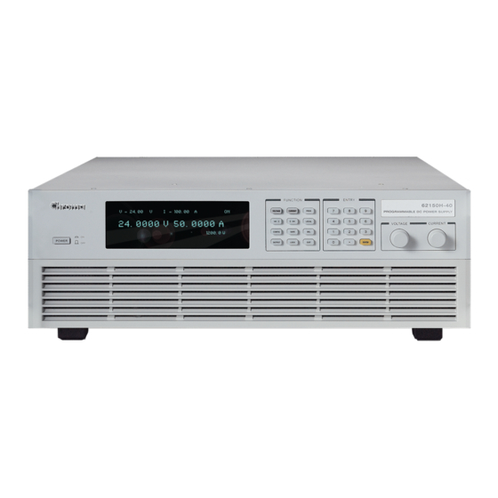
Programmable DC Power Supply (with Solar Array Simulation) 62000H Series Operating & Programming Manual 62050H-600S ±1200 62100H-600S ±1200 62150H-600S ±1200 62150H-1000S ±1200 A620028 ±1200 A620027 ±1200 If the voltage exceeds the above range it may result in damage to the DC Power Supply. - Page 33 Overview Figure 1-5 Front Panel of 62020H-150S with Solar Array Simulation Table 1-5 Description of Front Panel Item Symbol Description Display: VFD Display: displays the output settings and measurement results. Numeric and Decimal Point Keys: ● Numeric keys and the decimal point key to enter digital data.
-
Page 34: Rear Panel
Programmable DC Power Supply (with Solar Array Simulation) 62000H Series Operating & Programming Manual Item Symbol Description Cursor Movement Keys: Use the “ ” and “ ” keys to move the cursor to the parameter to be modified. Voltage Rotary Knob: Turn the knob “... - Page 35 Overview Figure 1-7 Rear Panel of Slave Model A620027/A620028 Figure 1-8 Rear Panel of 62020H-150S with Solar Array Simulation Table 1-6 Description of Rear Panel Item Name Description RS-232C /RS-485 9-pin D type male connector. The control commands are transmitted between power supply and PC for remote control.
- Page 36 Programmable DC Power Supply (with Solar Array Simulation) 62000H Series Operating & Programming Manual configuration. When the GPIB/ETHERNET interface is selected as the shipping default, it will be installed before shipment as shown in Figure 1-9 (a) & (b). (a) GPIB Interface (b) ETHERNET Interface Figure 1-9 1-14...
-
Page 37: Installation
Checking the Package (1) After unpacking, check if there is any damage or any missing accessories. (2) If any damage is found, contact “Chroma RMA” immediately to request a return shipment. Figure 2-1 (a), (b), (c), (d), (e), (f), (g) and (h) are the accessories. -
Page 38: Maintenance & Cleaning
Use a damp cloth with soapy water or soft detergent to clean the LCD front panel. For internal cleaning, use a low-pressure air gun to remove the dust inside or send it back to a Chroma agent for cleaning. Preparation for Use (1) Remove the iron holder on the front panel as shown in Figure 2-2 and keep it in case the Power Supply needs to be returned for service. -
Page 39: Normal Environment Conditions
Supply. Scrape off any coating on the power cable tip (the bare portion is about 1cm) and use an O type terminal to crimp it. (For the 62020H-150S, the bare portion needs to be tinned.) Secure the power cable to the input terminal with a Phillips screwdriver with a lock torque in the 30-40 (kg-cm) range. - Page 40 Connect the black or brown metal wire to the “L1, L2, L3” terminals. Figure 2-5 shows the suggested specification of an O type terminal. Figure 2-5 Connect the white or blue metal wire of the 62020H-150S to the “N” terminal.
-
Page 41: Remote Sensing
Installation Connect the black or brown metal wire of the 62020H-150S to the “L” terminal. To protect the operator, the wire connected to the GND terminal WARNING ) must be connected to the earth. This DC Power Supply must be operated with an adequate ground connection. - Page 42 (see specification) it will cause a protection error as shown in Figure 2-8 indicating it is unable to compensate for the voltage drop. Connect the remote sensing wire of the 62020H-150S as shown in Figure 2-7. The remote sensing wire needs to be connected to the DC Power Supply local output or the remote input of the UUT.
-
Page 43: Reverse Connection Of Remote Sensing Wire Polarity
The output connector of the 62000H Series DC Power Supply with Solar Array Simulation is located in the upper middle area on the rear panel and for the 62020H-150S it is on the left side of the rear panel. The load is connected to the “+” and “–” output terminals. - Page 44 Programmable DC Power Supply (with Solar Array Simulation) 62000H Series Operating & Programming Manual Figure 2-9 Figure 2-10...
-
Page 45: Connecting Wire Specifications
Make sure the wire connected to the load is able to carry the maximum applied current. There is no need to use the 62020H-150S 9PIN current sharing cable when using the device in standalone mode. CAUTION Do not exceed the rated output current (different for each model in the 62000H Series). -
Page 46: Parallel Capacitance Specifications
Programmable DC Power Supply (with Solar Array Simulation) 62000H Series Operating & Programming Manual shown in Figure 2-12. For other models, contact your Chroma agent. Be sure to use the proper diameter wire to avoid overheating. Figure 2-12 2.5.3 Parallel Capacitance Specifications The maximum parallel output capacitance varies according to the 62000H Series Models as shown in Table 2-2. -
Page 47: Power-On Procedure
Installation Figure 2-13 Installing the Handle Power-On Procedure Plug in the power cord and turn ON the power switch on the front panel. The DC Power Supply will run a series of self-tests. The VFD on the front panel will light up and display the following: S E L F T E S T . - Page 48 Programmable DC Power Supply (with Solar Array Simulation) 62000H Series Operating & Programming Manual When the memory, data, and communication self tests are done, the screen goes to the MAIN PAGE automatically, as shown below: V = 0. 0 0_ = 0.
-
Page 49: Manual Operation
Manual Operation Manual Operation Introduction The DC Power Supply can be operated manually or remotely via a GPIB/ETHERNET (option), USB, RS-232/RS-485, or APG interface as described in Chapter 5 and section 3.3.1.1. Manual operation using the front panel keyboard or rotary knobs to input the data is described in this chapter. -
Page 50: Setting Configuration
Programmable DC Power Supply (with Solar Array Simulation) 62000H Series Operating & Programming Manual To set the current (CC MODE): CURR Press “ ”. The remaining steps are the same as the voltage settings, as shown in Figure 3-2. (To keep the output in CC mode the voltage setting must be larger than the load voltage; otherwise, the output current will not be equal to the set current.) V = 0. - Page 51 Manual Operation Use the numeric keys ( ) or the “Rotary” ( ) knob to select the item to be set. Press “ ” to confirm. ENTER Press “ ” to return to the MAIN PAGE. EXIT EXIT To cancel the setting, press “ ”...
- Page 52 Programmable DC Power Supply (with Solar Array Simulation) 62000H Series Operating & Programming Manual Figure 3-4...
-
Page 53: System Setup
Manual Operation 3.3.1 SYSTEM SETUP ENTER In the Config setup page, press “ ” then “ ” to display the screen shown in Figure 3-5. Use the “ ”, “ ” keys to move the cursor to the desired selection. [S Y S T E M S E T U P] A P G V S E T N O N E _... - Page 54 Programmable DC Power Supply (with Solar Array Simulation) 62000H Series Operating & Programming Manual For APG ISET, use the numeric keys or the “Rotary” ( ) knob to set the mode. There are 5 selections for APG ISET: NONE / Vref(0-5V) / Vref(0-10V) / Iref(4-20mA) / Rref(0-5KOhm), where: NONE: means not using the programming function.
- Page 55 Manual Operation 600V/0A ~ 25A will map to 4-20mA as shown in Figure 3-7 (c). d. Selecting Vref=5KOhm means the DC Power Supply’s output 0V - 600V/0A ~ 25A will map to 0-5KOhm as shown in Figure 3-7 (d). 600V/25A 600V/25A APG INPUT 5V APG INPUT 10V...
- Page 56 Programmable DC Power Supply (with Solar Array Simulation) 62000H Series Operating & Programming Manual 600V/25A 600V/25A APG OUTPUT 5V APG OUTPUT 10V 600V/25A APG OUTPUT 4mA~20mA Figure 3-8 Calibrate the APG settings and measurements before using APG control. When setting the APG VMEAS/APG IMEAS to Iref(4-20mA) mode, ensure the series resistance does not exceed 500Ω...
- Page 57 Manual Operation +12VAPI API GND AVO_SET_R AIO_SET_R AVO_SET_C AIO_SET_C AVO_SET_V AIO_SET_V AVO_MEAS_C AIO_MEAS_C AVO_MEAS_V AIO_MEAS_V sensing sensing sensing sensing Figure 3-10 APG Interface pin definitions: Auxiliary power Vcc: outputs +12Vdc with a maximum output current of 10mA (output port). Voltage programming: inputs the resistance (0-5K Ohm) between this pin and APIGND to linearly control the output voltage (CV mode).
-
Page 58: Buzzer
Programmable DC Power Supply (with Solar Array Simulation) 62000H Series Operating & Programming Manual Current programming: inputs the analog voltage (0-10Vdc or 0-5Vdc) between this pin and APIGND to linearly control the output current (CC mode). Current measurement: outputs the analog current (4mA-20mA) for monitoring. Current measurement: outputs the analog voltage (0-5V or 0-10V) for monitoring. - Page 59 Manual Operation [S Y S T E M S E T U P] A P G V S E T N O N E A P G I S E T N O N E A P G V M E A S N O N E A P G I M E A S N O N E...
-
Page 60: Output Setup
Programmable DC Power Supply (with Solar Array Simulation) 62000H Series Operating & Programming Manual [S Y S T E M S E T U P] A P G V S E T N O N E A P G I S E T N O N E A P G V M E A S N O N E... -
Page 61: Voltage Limit Setting
Manual Operation 3.3.2.1 VOLTAGE LIMIT SETTING Use the “ ”, “ ” keys to move the cursor to the column to be set as shown in Figure 3-16. Figure 3-16 Use the numeric keys ( ) or the “Rotary” ( ) knob to set the value. -
Page 62: Current Limit Setting
Programmable DC Power Supply (with Solar Array Simulation) 62000H Series Operating & Programming Manual 3.3.2.2 CURRENT LIMIT SETTING Use the “ ”, “ ” keys to move the cursor to the column to be set as shown in Figure 3-18. Figure 3-18 Use the numeric keys ( ) or the “Rotary”... -
Page 63: Voltage Slew Rate
Manual Operation 3.3.2.3 VOLTAGE SLEW RATE Use the “ ”, “ ” keys to move the cursor to the column to be set as shown in Figure 3-20. Figure 3-20 Use the numeric keys ( ) or the “Rotary” ( ) knob to set the value. -
Page 64: Current Slew Rate Setting
Programmable DC Power Supply (with Solar Array Simulation) 62000H Series Operating & Programming Manual 3.3.2.4 CURRENT SLEW RATE SETTING Use the “ ”, “ ” keys to move the cursor to the column to be set. Figure 3-22 Use the numeric keys ( ) or the “Rotary”... -
Page 65: Setting Dc_On
Manual Operation 3.3.2.5 Setting DC_ON The DCOUT_ON signal on the ANALOG INTERFACE can be set to follow the rising and falling edges of the voltage waveform or the position of the OUTPUT button on the front panel. If the DCOUT_ON signal is set to VDC_R/F and the voltage is over VDC_R, pin10 DCOUT_ON on the ANALOG INTERFACE will go HIGH. -
Page 66: Setting Iv Curve Parameters
Programmable DC Power Supply (with Solar Array Simulation) 62000H Series Operating & Programming Manual Figure 3-26 Use the numeric keys ( ) or the “Rotary” ( ) knob to set DCOUT_ON MODE to ON/OFF, which causes pin10 on the ANALOG INTERFACE to follow the OUTPUT button on the front panel. - Page 67 Manual Operation Iset2 Iset2 Iset2 Iset1 Iset1 Iset1 Vset2 Vset2 Vset1 Vset1 (a) CC Mode (a) CC Mode (b) CV Mode (b) CV Mode Figure 3-28 Set the CONTROL MODE as described below: Use the “ ”, “ ” keys to move the cursor to the column to be set as shown in Figure 3-27.
- Page 68 Programmable DC Power Supply (with Solar Array Simulation) 62000H Series Operating & Programming Manual 3.3.2.6.3 Setting OUTPUT SPEED OUTPUT SPEED sets the output response speed of the IV Curve to FAST, MIDDLE or SLOW. The sequence for the output response speed setting is FAST > MIDDLE > SLOW. Use the “...
-
Page 69: Series/Parallel
CURRENT SHARING (100CM) cable is required. Contact the CHROMA Service Center or local agent for further information. No more than 2 units may be paralleled when placed horizontally. . Firmware versions 2.00 and above are not backward compatible. -
Page 70: Connecting Series/Parallel Output Cables
Assembling Series/Parallel Communication Interface When the DC Power Supplies are connected in series, the SYSTEM BUS connectors on the rear panel must be connected as shown in Figure 3-34(a.). For the 62020H-150S, connect the cables as shown in Figure 3-34(b). - Page 71 When the DC Power Supplies are connected in parallel, both the SYSTEM BUS and CURRENT SHARING connectors must be connected as shown in Figure 3-35 (a) [and Figure 3-35 (b) for the 62020H-150S]. For the A620028 and A620027 the MASTER unit and ANALOG must be connected as shown in Figure 3-36.
- Page 72 Figure 3-34 or Figure 3-35. For the 62020H-150S, connect the 15P 1 to 2 cable labeled “REAL” to the rear panel; also connect the two cables as shown in Figure 3-34 or Figure 3-35.
-
Page 73: Setting Series/Parallel Operation Mode
Manual Operation Do not connect the CURRENT SHARING cable when in series operation as it could cause a malfunction or damage the unit. Do not connect the CURRENT SHARING cable when operated standalone as it could cause a malfunction or damage the unit. Remove the SYSTEM BUS and CURRENT SHARING signal cables when returning to standalone operation as it could cause a malfunction or damage the unit if they remain connected. - Page 74 Programmable DC Power Supply (with Solar Array Simulation) 62000H Series Operating & Programming Manual Use the “ ”, “ ” keys to move the cursor to the M/S TERMINATOR selection item. Use the numeric keys ( ) or the “Rotary” ( ) knob to ENABLE or DISABLE the TERMINATOR as shown in Figure 3-38.
- Page 75 Manual Operation 4. Use the numeric keys ( ) or the “Rotary” ( ) knob to ENABLE or DISABLE the TERMINATOR as shown in Figure 3-39. ENTER 5. Press “ ” to confirm. Description of M/S TERMINATOR When the 62000H Series Models with Solar Array Simulation are operating in MASTER OR SLAVE mode, be aware of the M/S TERMINATOR setting.
- Page 76 Programmable DC Power Supply (with Solar Array Simulation) 62000H Series Operating & Programming Manual Connect the cables on the rear panel as shown in Figure 3-34 when set to SERIES and as shown in Figure 3-35 when set to PARALLEL. Selecting SERIES will display the window shown in Figure 3-42 to remind the user to disconnect the CURRENT SHARING cable on the rear panel.
- Page 77 Manual Operation Using the 62150H-600S as an example: If there are 5 sets connected in parallel for 600V/100A, each unit should be set for 600V/20A and the total output will be 600V/100A. If there are 2 sets connected in series for 1200V/25A, each unit should be set for 600V/25A and the total output will be 1200V/25A.
-
Page 78: Setting Series Parameters
Programmable DC Power Supply (with Solar Array Simulation) 62000H Series Operating & Programming Manual O N L I N E S L A V E 1 Figure 3-46 5. The units are now ready to be used in the series/parallel mode. CAUTION Communication errors will occur if the SLAVE settings are the same (such as SLAVE 1 &... - Page 79 Manual Operation ∑ V = 6 0. 0 0 _ V = 1 0. 0 0 M S T O F F 0 . 0 0 0 0 V 0 . 0 0 0 0 A 0 . 0 W Figure 3-48 3.3.3.4.2 Setting SYSTEM SETUP for Series...
-
Page 80: Setting Parallel Parameters
Programmable DC Power Supply (with Solar Array Simulation) 62000H Series Operating & Programming Manual [O U T P U T S E T U P] ΣV L I M I T : M A X = 6 0 0 . 0 _ V M I N = 0 . - Page 81 Manual Operation ∑ I V = 6 0. 0 0 _ V = 1 0. 0 0 M S T O F F 0 . 0 0 0 0 V 0 . 0 0 0 0 A 0 . 0 W Figure 3-52 3.3.3.5.2 Setting SYSTEM SETUP for Parallel...
-
Page 82: Setting Procedure For Apg In Series Or Parallel
Programmable DC Power Supply (with Solar Array Simulation) 62000H Series Operating & Programming Manual [O U T P U T S E T U P] L I M I T : M A X = 6 0 0 . 0 _ V M I N = 0 . - Page 83 Manual Operation The external analog voltage 0-5V maps to the actual output voltage (0-1200V) and the actual output current (0-25A) as shown in Figure 3-57(a). When the APG option is set to APG VSET/APG ISET = Vref(0-10V) the external analog voltage 0-10V maps to the actual output voltage (0-1200V) and the actual output current (0-25A) as shown in Figure 3-57(b).
-
Page 84: Display
Programmable DC Power Supply (with Solar Array Simulation) 62000H Series Operating & Programming Manual 600V/125A 600V/125A APG INPUT 5V/5V APG INPUT 10V/10V Figure 3-59 3.3.4 DISPLAY The DISPLAY setting has 4 options: (1) BRIGHTNESS (2) DISPLAY SELECTION (3) READING AVERAGE TIMES (4) AVERAGE METHOD. 3.3.4.1 BRIGHTNESS This option sets the backlight panel brightness of the VFD on the front panel. -
Page 85: Display Selection
Manual Operation Settings and brightness descriptions: Press “ ”, BRIGHTNESS = HIGH. Press “ ”, BRIGHTNESS = NORMAL. Press “ ”, BRIGHTNESS = DIMMED. The lower the backlight brightness, the longer the display panel life. Set the backlight brightness to DIMMED when the device is doing burn-in to prolong the product life of the VFD display. - Page 86 Programmable DC Power Supply (with Solar Array Simulation) 62000H Series Operating & Programming Manual V = 6 0. 0 0 = 1 0. 0 0 _ O F F 0 . 0 0 0 0 V 0 . 0 0 0 0 A 0 .
-
Page 87: Reading Average Times
Manual Operation 3.3.4.3 READING AVERAGE TIMES The READING AVERAGE TIMES sets the number of samples to be averaged and displayed on the MAIN PAGE screen. The default is 2. When changing the READING AVERAGE TIMES default, the average method can also be changed. [ D I S P L A Y S E T U P ] B R I G H T N E S S = H I G H... -
Page 88: Protection
Operating & Programming Manual 3.3.5 PROTECTION Chroma 62000H Series DC Power Supplies with Solar Array Simulation have protection functions divided into two classes. The first protection class includes over voltage, over current, over power and FOLDBACK; the second protection class includes over temperature, fan failure and over/under input voltage. -
Page 89: Ocp Protection
Manual Operation Use the numeric keys ( ) or the “Rotary” ( ) knob to set the value. ENTER Press “ ” to confirm. EXIT Press “ ” to return to the MAIN PAGE. This function sets the protection point for Over Voltage. If the output voltage exceeds the range, it will turn off the output to protect the unit under test. -
Page 90: Opp Protection
Programmable DC Power Supply (with Solar Array Simulation) 62000H Series Operating & Programming Manual This function sets the protection point for Over Current. If the output current exceeds the range, it will turn off the output to protect the unit under test. Table 3-3 shows the current range of OCP. -
Page 91: Remote Inhibit
Manual Operation Table 3-4 shows the power range of OPP. Table 3-4 Model Min. OPP (W) Max. OPP (W) 62xxxH-xxxxS 1.05 x Po_MAX The OPP protection point is based on the comparison of the calculated power of the output current and remote sense voltage. If an OPP occurs the MAIN PAGE will displaty a protection message as shown in Figure 3-74. - Page 92 Programmable DC Power Supply (with Solar Array Simulation) 62000H Series Operating & Programming Manual Selecting ENABLE: Sets the REMOTE INHIBIT to ENABLE. The DC Power ON/OFF Supply’s ON/OFF is still controlled by the “ ” key. When Pin 9 (_INHIBIT) of the ANALOG INTERFACE is ON/OFF triggered by a Low Level (same as pressing the “...
-
Page 93: Safety Int.lock
Manual Operation _INHIBIT SIGNAL Output INHIBIT =DISABLE Output INHIBIT =ENABLE Figure 3-77 3.3.5.5 SAFETY INT.LOCK This function controls the power supply’s ON/OFF function directly through Pin 21 (INTERLOCK) of the ANALOG INTERFACE. Use the “ ” “ ” keys to move the cursor to the column to be set as shown in Figure 3-78. - Page 94 Programmable DC Power Supply (with Solar Array Simulation) 62000H Series Operating & Programming Manual 21 of the ANALOG INTERFACE is returned to a low level, the DC Power Supply will continue to output normally. ENTER Press “ ” to confirm. EXIT Press “...
-
Page 95: External On/Off
Manual Operation 3.3.5.6 EXTERNAL ON/OFF This function controls the DC Power Supply’s ON/OFF through Pin 22 (_EXT_ON) of the ANALOG INTERFACE. Use the “ ”, “ ” keys to move the cursor to the column to be set as shown in Figure 3-81. -
Page 96: Foldback
Programmable DC Power Supply (with Solar Array Simulation) 62000H Series Operating & Programming Manual Pin 22 is a TTL Level input pin. The initial state can be set to PULL=HIGH or PULL=LOW. When the DC Power Supply is set to OUTPUT = ON, the EXTERNAL ON/OFF signal will control the output as shown in Figure 3-83. - Page 97 Manual Operation DISABLE: Ignore the output off function. CV TO CC: Active in CV MODE only. When the mode is changed to CC MODE, the system will turn off the output to protect the UUT. CC TO CV: Active in CC MODE only. When the mode is changed to CV MODE, the system will turn off the output to protect the UUT.
-
Page 98: Otp
Programmable DC Power Supply (with Solar Array Simulation) 62000H Series Operating & Programming Manual CV MODE DC SOURCE OPERATION MODE DELAY TIME Time FOLDBACK PROTECTION CC MODE Figure 3-87 Assuming the FOLDBACK is set to CV TO CC, the solid line in Figure 3-87 indicates when Foldback protection occurs while the dotted line indicates when it will not occur. -
Page 99: Ac Fault
Manual Operation 3.3.5.9 AC FAULT The AC FAULT protection will activate when the internal input voltage is not within the model’s range, or when the input voltage is too low. The output will turn OFF. If an AC FAULT occurs, the MAIN PAGE will display a protection message as shown in Figure 3-89. -
Page 100: 3.3.5.11 Fanlock Protection
Programmable DC Power Supply (with Solar Array Simulation) 62000H Series Operating & Programming Manual (2) The voltage drop across the load wire exceeds the full scale output voltage by 4%, protection will occur when the load wire voltage drop > 600 x 0.04=24V (using the 62150H-600S as an example). -
Page 101: 3.3.5.12 D/D Fault Protection
Manual Operation CAUTION Troubleshooting: (1) If a FANLOCK protection occurs, power OFF the instrument and then power it ON again to see if it is a false error. (2) If the FANLOCK protection occurs again, contact a sales agent for repair services. Keep the two sides and the rear of the DC Power Supply clear when operating to prevent an Over Temperature Protection fault from occurring. -
Page 102: 3.3.5.14 Fpga Update! Protection
This protection occurs when the device firmware has been upgraded to 2.00 but the FPGA is not upgraded to version 1.11 or above. When FPGA UPDATE! occurs, the main screen will display the message as shown in Figure 3-94. Figure 3-94 Troubleshooting: Contact a local Chroma agent if an FPGA UPDATE! occurs. 3-54... -
Page 103: 3.3.5.15 C/S Cable Err. Protection
HOOP hole on the rear panel as shown in Figure 2-10 (the SLAVE models A620028 and A620027 are not included) (3) Contact a local Chroma agent for the hardware upgrade. 3-55... -
Page 104: 3.3.5.16 Match Warning
Programmable DC Power Supply (with Solar Array Simulation) 62000H Series Operating & Programming Manual CAUTION The DC Power Supply could malfunction or be damaged if the CURRENT SHARING cable is connected incorrectly when in parallel mode. Do not connect the CURRENT SHARING cable during series operation. - Page 105 Figure 3-99 3.3.7 CALIBRATION Chroma 62000H Series DC Power Supplies with Solar Array Simulation provide calibration functions (1) - (5), the A620028 and A620027 provide calibration functions (1)(2)(3) and the 62020H-150S model provides calibration functions (1) - (7): (1) VOLTAGE: the actual output voltage (CV mode) and the measurement accuracy.
-
Page 106: Calibration
[ P R O G . / M E A S . ] Figure 3-101 The slave models (A620028/A620027) of the Chroma 62000H Series DC Power Supplies with Solar Array Simulation have 3 CALIBRATION functions: (1) VOLTAGE: the actual output voltage (CV mode) and the measurement accuracy. - Page 107 The MASTER provides the panel output for the SLAVE. The load and measurement cables for the actual calibration need to be installed on the SLAVE. The DC Power Supply should be calibrated every year. Contact Chroma for further information. 3-59...
-
Page 108: Voltage Output & Measurement Calibration
Programmable DC Power Supply (with Solar Array Simulation) 62000H Series Operating & Programming Manual 3.3.7.1 Voltage Output & Measurement Calibration 3.3.7.1.1 Hardware Requirement The hardware requirement is shown in Table 3-6. Table 3-6 Device Suggested Model or Capacity HP 34401A or equivalent DVM 3.3.7.1.2 SETUP The setup is shown in... - Page 109 Manual Operation ENTER In the Voltage calibration page, press “ ” to confirm. The low voltage range calibration is done first. The instrument will set the output voltage to 8.00V and the cursor stops at position [1] as shown in Figure 3-107. Enter the voltage ENTER measured by the DVM and press “...
-
Page 110: Current Measurement Calibration
CURRENT SHUNT Prodigit 7550 or ULTRASTAB SATURN or equivalent LOAD ELECTRICAL LOAD CHROMA 63204 or equivalent BREAKER Current >=100A The table above lists the BREAKER capacity for the 62150H-600S CAUTION only. For the applicable BREAKER capacity for other models, see the specifications for OUTPUT CURRENT in Table 1-1. - Page 111 Manual Operation Current Shunt − − 62000H Electronic Load DC Power Supply − − − Breaker Figure 3-110 Calibrate the offset voltage of the ULTRASTAB SATURN before using Null it for the current calibration. Press “ ” and the DVM panel digits will reset and show “Math”...
- Page 112 Programmable DC Power Supply (with Solar Array Simulation) 62000H Series Operating & Programming Manual [ C U R R E N T M E A S C A L I B R A T I O N ] A P P L Y L O A D I N G A N D P R E S S [ E N T E R ] S E T L O A D I N G...
-
Page 113: Current Output (Prog.) Calibration
Manual Operation 11. Once the 7.5A point is calibrated, it is important to turn the loading of the Electronic Load off and reconnect the DC Power Supply to a current shunt whose rating is closest to but still covers 20A. For the Prodigit 7550, use 20A shunt directly. 12. - Page 114 CURRENT SHUNT Prodigit 7550 or ULTRASTAB SATURN or equivalent LOAD ELECTRICAL LOAD CHROMA 63204 or equivalent BREAKER Current >=100A The table above lists the BREAKER capacity for the 62150H-600S CAUTION only. For the applicable BREAKER capacity for other models, see the specifications for OUTPUT CURRENT in Table 1-1.
- Page 115 Manual Operation [ C U R R E N T S E T T I N G C A L I B R A T I O N ] S H O R T O U T P U T T E R M I N A L A N D P R E S S [ E N T E R ]...
- Page 116 Programmable DC Power Supply (with Solar Array Simulation) 62000H Series Operating & Programming Manual [ C U R R E N T S E T T I N G C A L I B R A T I O N ] S E T T I N G O U T P U T C U R R E N T = 4 .
-
Page 117: Apg Voltage Calibration
Manual Operation ENTER EXIT set SAVE=YES and press “ ” to save it. If there is no need to save it, press “ ” to return to the Calibration screen. [ S A V E A R G U M E N T ] S A V E = N O Figure 3-124 EXIT... - Page 118 Programmable DC Power Supply (with Solar Array Simulation) 62000H Series Operating & Programming Manual AVO_MEAS +12VAPI API GND AVO_SETV − − − DC Power DVM 1 DVM2 Supply Figure 3-125 Key in at least 5 digits for each calibration point to ensure the Power Supply accuracy after calibration.
- Page 119 Manual Operation [ A P G V O L T A G E C A L I B R A T I O N ] C H E C K A P G C O N N E C T I O N A N D P R E S S [ E N T E R ] ( S E T ) I N P U T...
-
Page 120: Apg Current Calibration
Programmable DC Power Supply (with Solar Array Simulation) 62000H Series Operating & Programming Manual [ S A V E A R G U M E N T ] S A V E = N O Figure 3-129 EXIT Press “ ”... - Page 121 Manual Operation Key in at least 5 digits for each calibration point to ensure the Power Supply accuracy after calibration. 3.3.7.5.3 Calibration Procedure (Example: Model 62150H-600S) In the CALIBRATION page, press “ ” or turn the “Rotary” ( ) knob to set CHOICE = 5.
-
Page 122: Voltage Output & Measurement Calibration (62020H-150S Only)
” to return to the MAIN PAGE. The calibration points may be different for other models (non 62150H-600S); perform the calibration following the instructions displayed. 3.3.7.6 IV Voltage Output & Measurement Calibration (62020H-150S Only) 3.3.7.6.1 Hardware Requirements The hardware required for calibration is shown in Table 3-11. - Page 123 Set the Resolution of the HP34401 to SLOW 6 digit. Key in at least 5 digits for each calibration point to ensure the Power Supply accuracy after calibration. This calibration function is only valid for the 62020H-150S. 3.3.7.6.3 Calibration Procedure Go to the CALIBRATION the screen as shown in Figure 3-136.
- Page 124 Programmable DC Power Supply (with Solar Array Simulation) 62000H Series Operating & Programming Manual ENTER Verify the external load has been removed and press “ ” to confirm. The device will output 10.00V and the cursor will stop at position [1] as shown in Figure ENTER 3-138.
-
Page 125: Current Calibration (62020H-150S Only)
S A V E = N O Figure 3-140 EXIT 10. Press “ ” to return to the MAIN PAGE. 3.3.7.7 IV Current Calibration (62020H-150S Only) 3.3.7.7.1 Hardware Requirements The hardware required for current calibration is shown in Table 3-12. Table 3-12... - Page 126 Programmable DC Power Supply (with Solar Array Simulation) 62000H Series Operating & Programming Manual digits will reset and show “Math” for the current calibration. Key in at least 5 digits for each calibration point to ensure the Power Supply accuracy after calibration. 3.3.7.7.3 Calibration Procedure Go to the CALIBRATION page as shown in Figure 3-136.
- Page 127 Manual Operation [C U R R E N T M E A S C A L I B R A T I O N ] A P P L Y L O A D I N G A N D P R E S S[ E N T E R ] S E T L O A D I N G C U R R E N T...
-
Page 128: Remote Setup
Programmable DC Power Supply (with Solar Array Simulation) 62000H Series Operating & Programming Manual ENTER EXIT “ ” to save it. If there is no need to save it, press “ ” to return to the Calibration screen. [ S A V E A R G U M E N T ] S A V E = N O Figure 3-147 EXIT... - Page 129 Manual Operation Connect the network cable to the DC Power Supply for auto detection. If the network cable is not connected properly, it may cause the DC Power Supply screen to display incorrectly. Turn OFF the DC Power Supply, resolve the network cable problem, and reboot it to clear the abnormal screen.
-
Page 130: Rs232/Rs485
Programmable DC Power Supply (with Solar Array Simulation) 62000H Series Operating & Programming Manual [R E M O T E S E T U P] D H C P A D D R E S S = 2 5 5 . 2 5 5 . 2 5 5 . 2 5 5 G A T E W A Y A D D R = 2 5 5 . -
Page 131: Baudrate
Manual Operation 3.3.8.4 BAUDRATE The DC Power Supply supports remote operation through the RS232 interface. The RS232 baudrate must be set prior to remote operation. Use the “ ”, “ ” keys to move the cursor to the BAUDRATE column as shown in Figure 3-152. -
Page 132: Rs485 Terminator
Programmable DC Power Supply (with Solar Array Simulation) 62000H Series Operating & Programming Manual Press “ ” to confirm. ENTER Press “ ” to return to the MAIN PAGE. EXIT The valid address range is 1-30. 3.3.8.6 RS485 TERMINATOR The terminator status needs to be set when using the RS485 remote operation function. Use the “... -
Page 133: Output Mode
See the A620029 User’s Manual for setup instructions. The DC power supply firmware must be version 2.00 or above when used with the A620029. Version 2.00 firmware is not backward compatible. Contact Chroma if a firmware upgrade is required. 3.3.9 OUTPUT MODE 62000H Series DC Power Supplies with Solar Array Simulation have 5 operating modes: (1) CV/CC MODE: the common CV MODE and CC MODE of a DC Power Supply. -
Page 134: Cv/Cc Mode
3.3.9.1 CV/CC MODE The Chroma 62000H Series DC Power Supply with Solar Array Simulation can also be used as a general purpose DC Power Supply. The supply provides CV and CC modes as shown in Figure 3-157. See section 3.2 for detailed operating procedures. - Page 135 Manual Operation Figure 3-158 Figure 3-159 shows the screen display when using the Solar Array Simulation Soft Panel. The settings cannot be changed from the front panel. V O C = 1 0 0 . 0 0 V _ I S C = 1 0 . 0 0 0 A V M P = 6 0 .
-
Page 136: Sas Mode
3.3.9.3 SAS MODE The Chroma 62000H Series DC Power Supply with Solar Array Simulation is not only able to simulate the Solar Cell curve using the Solar Array Simulation Soft Panel but it also has a built-in model to provide a solar cell curve simulation function called SAS Mode. See Britton, Lunscher, and Tanju, "A 9 KW High-Performance Solar Array Simulator", Proceedings of the... - Page 137 Manual Operation Procedure for selecting the SAS MODE: Use the numeric keys or the “Rotary” ( ) knob to select SAS_MODE as shown in Figure 3-161. Press “ ” to confirm. ENTER Press “ ” to return to the MAIN PAGE. EXIT Figure 3-161 Figure 3-162 shows the screen in the SAS MODE.
- Page 138 Programmable DC Power Supply (with Solar Array Simulation) 62000H Series Operating & Programming Manual Figure 3-163 Press “ ON/OFF ” again to start program execution. The SAS MODE main screen will display as shown in Figure 3-164. To quit, press “ ”...
- Page 139 (1s @ No Load) (40ms @ 1500W ) (8ms @ 7500W ) Delta V=350 to 250V (160ms @ No Load) (6.6ms @ 1500W ) (1.4ms @ 7500W ) 62020H-150S Delta V= 150 to 0V (120ms @ No Load) (16ms @ 200W ) 3-91...
-
Page 140: En50530 Mode
(1.5ms @ 200W ) (0.3ms @ 1000W ) 3.3.9.4 EN50530 MODE The Chroma 62000H Series Programmable DC Power Supply with Solar Array Simulation has EN50530 built-in to provide a solar cell curve simulation function. Use the numeric keys or the rotary knob ( ) to select EN50530_MODE as shown in Figure 3-165. -
Page 141: Sandia Mode
3.3.9.5 SANDIA MODE The Chroma 62000H Series Programmable DC Power Supply with Solar Array Simulation has SANDIA_MODE built-in to provide a solar cell curve simulation function. Use the numeric keys or the rotary knob ( ) to select SANDIA_MODE as shown in Figure 3-169. - Page 142 Programmable DC Power Supply (with Solar Array Simulation) 62000H Series Operating & Programming Manual Figure 3-169 In SANDIA _MODE the display shows: Figure 3-170 Procedure for setting the SANDIA_MODE parameters: Move the cursor to VMP and use the numeric keys ( ) to set the maximum power voltage.
-
Page 143: Error Message
Manual Operation Figure 3-171 10. Press “ ON/OFF ” again to start program execution. The SANDIA_MODE main screen will display as shown in Figure 3-172. To quit, press “ ” to return to the MAIN PAGE. EXIT Figure 3-172 Figure 3-172 shows the screen during SANDIA_MODE output. The EQ_VOC, EQ_VMP, EQ_ISC and EQ_IMP are the actual operating points that are calculated based on the settings of VMP and PMP using the built-in formula. - Page 144 Programmable DC Power Supply (with Solar Array Simulation) 62000H Series Operating & Programming Manual Figure 3-173 If invalid parameters are entered in EN50530 or SANDIA_MODE or a parameter returns a negative value after the calculation has been completed, the screen will display an error EXIT message.
-
Page 145: Program Sequence
Program Sequence Program Sequence 62000H Series DC Power Supplies with Solar Array Simulation allow users to program the output sequence in LIST MODE, V_STEP MODE and IV PROGRAM. LIST MODE and IV PROGRAM both have 10 Programs and each Program can add a total of 100 sequences that are available for editing. -
Page 146: Description Of Program Settings
Programmable DC Power Supply (with Solar Array Simulation) 62000H Series Operating & Programming Manual [ PROGRAM ] EXT._TRIG PULL HIGH PROG NO. COUNT PROG CHAIN = NO CLEAR PROG = NO [ SEQUENCE ] TYPE = AUTO TIME = 0.000(S) VOLTAGE = 0.00V V S. -
Page 147: Setting Ext._Trig Pull
Program Sequence 4.1.1.1 Setting EXT._TRIG PULL Use the “ ”, “ ” keys to move the cursor to the column to be set as shown in Figure 4-3 (1). Use the numeric keys or the “Rotary” ( ) knob to set HIGH or LOW. ENTER Press “... - Page 148 Programmable DC Power Supply (with Solar Array Simulation) 62000H Series Operating & Programming Manual Each PROGRAM has a RUN COUNT that sets the number of times the program is executed. The following table shows the RUN COUNT range: Table 4-1 RUN COUNT TIMES 15000...
-
Page 149: Setting Prog Chain
Program Sequence 4.1.1.4 Setting PROG CHAIN Use the “ ”, “ ” keys to move the cursor to the column to be set as shown in Figure 4-3 (4). Use the numeric keys or the “Rotary” ( ) knob to set YES or NO. The PROGRAM CHAIN indicates the link between programs. - Page 150 Programmable DC Power Supply (with Solar Array Simulation) 62000H Series Operating & Programming Manual START PROG #1 PROG #6 PROG CHAIN NO = 3 PROG CHAIN NO = 0 SEQ 1_1 ~ SEQ 1_10 SEQ 6_1 ~ SEQ 6_10 PROG #2 PROG #7 PROG CHAIN NO = 0 PROG CHAIN NO = 0...
- Page 151 Program Sequence START PROG #1 PROG CHAIN NO. = 1 SEQ 1_1 ~ SEQ 1_10 Figure 4-6 Ex.4: Use multiple PROGRAMS to form an infinite loop Set PROG #1 to NEXT TO PROG NO =3, RUN COUNT=1 PROG #3 to NEXT TO PROG NO =4, RUN COUNT=1 PROG #4 to NEXT TO PROG NO =6, RUN COUNT=1 PROG #6 to NEXT TO PROG NO =1, RUN COUNT=1 The program execution flow is shown in Figure 4-7.
-
Page 152: Setting Clear Program
Programmable DC Power Supply (with Solar Array Simulation) 62000H Series Operating & Programming Manual START PROG #1 PROG #6 PROG CHAIN NO. = 3 PROG CHAIN NO. = 1 SEQ 1_1 ~ SEQ 1_10 SEQ 6_1 ~ SEQ 6_10 PROG #2 PROG #7 PROG CHAIN NO. -
Page 153: Setting Sequence
Program Sequence Clear Program has two options: CLEAR PROG = YES / NO. The main function of Clear Program is to clear all sequences in that program. ENTER Press “ ” to confirm. EXIT Press “ ” to return to Figure 4-1. 4.1.2 Setting Sequence The default number of SEQUENCEs for each PROGRAM is 0. -
Page 154: Setting Sequence Number
Programmable DC Power Supply (with Solar Array Simulation) 62000H Series Operating & Programming Manual 4.1.2.1 Setting Sequence Number Use the “ ”, “ ” keys to move the cursor to the column to be set as shown in Figure 4-8 (1). When the cursor is at Figure 4-8 (7), press “... - Page 155 Program Sequence [ S E Q U E N C E ] S E Q S E Q T Y P E = A U T O _ T I M E 0 . 0 0 0 ( S ) V O L T A G E 0 .
- Page 156 Programmable DC Power Supply (with Solar Array Simulation) 62000H Series Operating & Programming Manual A5: Execution step: (1) SEQ#1: Since SEQ TYPE = AUTO is set for SEQ#1, it begins to execute the settings in SEQ#1. During the SEQ#1 voltage rise, the maximum loading current is 1A and does not exceed the current setting of 20A;...
- Page 157 Program Sequence [ S E Q U E N C E ] S E Q S E Q T Y P E = M A N U A L _ V O L T A G E 0 . 0 0 V S .
-
Page 158: Setting Time
Programmable DC Power Supply (with Solar Array Simulation) 62000H Series Operating & Programming Manual 4.1.2.3 Setting Time Use the “ ”, “ ” keys to move the cursor to the column to be set as shown in Figure 4-8 (3). Use the numeric keys or the “Rotary”... -
Page 159: Setting Current Slew Rate
Program Sequence 4.1.2.7 Setting Current Slew Rate Use the “ ”, “ ” keys to move the cursor to the column to be set as shown in Figure 4-8 (7). Use the numeric keys or the “Rotary” ( ) knob to set the SEQ current conversion slew rate. -
Page 160: Program List Mode Description
Programmable DC Power Supply (with Solar Array Simulation) 62000H Series Operating & Programming Manual ON/OFF Pressing “ ” in the Program page (Figure 4-3) or Sequence page (Figure 4-8) will display a confirmation page as shown in Figure 4-15. EXIT Pressing “... - Page 161 Program Sequence [ P R O G R A M / S T E P] S T A R T _ V O L T A G E = 0 . 0 0 E N D _ V O L T A G E = 0 .
-
Page 162: Setting End_Voltage
Programmable DC Power Supply (with Solar Array Simulation) 62000H Series Operating & Programming Manual 4.2.1.2 Setting END_VOLTAGE 1. Use the “ ”, “ ” keys to move the cursor to the column to be set as shown in Figure 4-19 (2). Set the end voltage of STEP MODE. 2. -
Page 163: Execution Of V_Step Mode
Program Sequence 10(MIN) START Figure 4-21 10(MIN) START Figure 4-22 4.2.2 Execution of V_STEP MODE ON/OFF Once all the sequences have been programmed, press “ ” to start execution. Press EXIT “ ” to stop execution. 4.2.2.1 Running V_STEP MODE ON/OFF 1. -
Page 164: Iv Program
Programmable DC Power Supply (with Solar Array Simulation) 62000H Series Operating & Programming Manual S T E P S T A T U S = A U T O E L A P S E T I M E = 0 : 5 0 S T A R T _ V O L T = 1 0 . -
Page 165: Setting Iv-Program
Program Sequence [ IV-PROGRAM ] PROG NO. COUNT PROG CHAIN = NO CLEAR PROG = NO [ IV-SEQUENCE ] IV-FILE NO. TYPE = AUTO TIME 0 (S) [ IV-SEQUENCE ] IV-FILE NO. TYPE = AUTO TIME 0 (S) [ IV-SEQUENCE ] IV-FILE NO. -
Page 166: Setting Iv-Sequence
Programmable DC Power Supply (with Solar Array Simulation) 62000H Series Operating & Programming Manual 4.3.2 Setting IV-Sequence The default number of IV-SEQUENCE(s) in an IV-PROGRAM is 0. Each IV-PROGRAM can add up to 100 sequences. The maximum number of IV-SEQUENCE(s) set in the 10 IV-PROGRAMS is 1000. -
Page 167: Setting Iv-File Number
Program Sequence number and return to a previously set Sequence Number. An IV-Program is able to add a maximum of 100 IV-Sequences, so the SEQ NO. range is 1-100. ENTER Press “ ” to confirm. EXIT Press “ ” to return to the IV-Program Page (Figure 4-26). 4.3.2.2 Setting IV-FILE Number IV-FILE NO. -
Page 168: Setting Time
Programmable DC Power Supply (with Solar Array Simulation) 62000H Series Operating & Programming Manual [ I V- S E Q U E N C E ] S E Q N O. I V – F I L E N O. = S E Q T Y P E A U T O _... -
Page 169: Execution Of Iv Program
Program Sequence 4.3.3 Execution of IV PROGRAM ON/OFF EXIT When the IV PROGRAM has been completed, press “ ” to confirm it and press “ ” to abort the execution. 4.3.3.1 Running IV PROGRAM ON/OFF Pressing “ ” will display the confirmation screen as shown in Figure 4-30. Figure 4-30 ON/OFF Press “... -
Page 170: Iv Program Main Screen
Programmable DC Power Supply (with Solar Array Simulation) 62000H Series Operating & Programming Manual 4.3.3.2 IV Program Main Screen When the IV PROGRAM is running, the main screen will display the following information. Items (1) - (10) in Figure 4-32 are described below. S E Q S T A T U S = A U T O T I M E = 0 0 0 : 0 0 : 20... -
Page 171: Remote Operation
Remote Operation Remote Operation Overview The 62000H Series DC Power Supply can be controlled remotely via the USB, GPIB, Ethernet, RS-232 or RS-485 ports. The USB interface supports USB 2.0/USB 1.1. The GPIB interface is an 8-bit parallel data bus that synchronizes with the host bus commands. - Page 172 Programmable DC Power Supply (with Solar Array Simulation) 62000H Series Operating & Programming Manual Table 5-1 Pin No. INPUT/OUTPUT Description “N.C.” INPUT OUTPUT “N.C.” Table 5-2 lists the connections between the PC (IBM compatible) and the 62000H Series DC Power Supply. Table 5-2 Pin No.
-
Page 173: Ethernet Remote Control
Remote Operation RS485_N The pin connections are shown below: Master (PC) RS485_P RS485_N Slave 1 Slave n (62000H) (62000H) 5.1.5 Ethernet Remote Control To remotely program the DC Power Supply via a PC using the Ethernet interface, the IP address, Gateway address and Subnet mask need to be set in advance. To ensure reliable data transmission, TCP is used for data transmission and the communication port is 2101. -
Page 174: Selecting The Lan To Be Connected
Programmable DC Power Supply (with Solar Array Simulation) 62000H Series Operating & Programming Manual 5.1.5.1 Selecting the LAN to be Connected The LAN is divided into two types: Site LAN and Private LAN. The Site LAN is a larger local area network such as an Intranet that contains the network server (DHCP, WINS, DNS, etc.), Terminator, Router, Firewall and Internet connection as shown below. - Page 175 The Private LAN is a smaller local area network that is composed of two or more terminators and a Hub or two terminators linked through a Crossover Cable. For the 62020H-150S Model, both a Crossover Cable and a Non-Crossover Cable can be used.
-
Page 176: Setting Ip, Subnet Mask & Gateway
Only the 62000H needs to be set up on the network. DHCP can be set to ON (the server sets the IP automatically) or OFF (set the IP manually.) For the 62020H-150S Model, refer to 7.2.1 for the network parameter settings. - Page 177 Remote Operation CONFIG PAGE 1. SYSTEM SETUP 2. OUTPUT SETUP 3. SERIES/PARALLEL 4.DISPLAY 5. PROTECTION 6.FACTORYSETTING 7. CALIBRATION 8. REMOTE GPIB ADDR ETHERNET = CONFIG DHCP:ON :XXX.XXX.XXX.XXX IP ADDRESS GATEWAY ADDR:XXX.XXX.XXX.XXX :XXX.XXX.XXX.XXX SUBNET MASK APPLY=YES LAN Status RS232/RS485 BAUDRATE STEP 2: Press to go to APPLY and set to YES to confirm sending out the settings.
- Page 178 STEP 4: Save the settings and return to the panel main screen. Procedure for setting DHCP = OFF on Chroma DC Source 62000H STEP 1: Set the IP, GATEWAY and SUBNET MASK parameters manually when DHCP=OFF. If the Site LAN parameters are not known, contact the network administrator and request the settings for the network parameters.
- Page 179 In most situations the PC will not have a DHCP Server. In a Private LAN, the IP addresses of all connected network devices need to be set manually. For the 62020H-150S Model, refer to section 7.2.1 for the network parameter settings.
- Page 180 Programmable DC Power Supply (with Solar Array Simulation) 62000H Series Operating & Programming Manual STEP 3: Double-click “Internet Protocol (TCP/IP)” to enter the configuration screen. 5-10...
-
Page 181: Confirming Network Connected Successfully
5.1.5.3 Confirming Network Connected Successfully When all of the steps above have been completed, the local area network of the Chroma DC Source 62000H should be ready to use. Follow the steps below to confirm the local area network setup is correct. - Page 182 Programmable DC Power Supply (with Solar Array Simulation) 62000H Series Operating & Programming Manual STEP 2: Input “cmd” and click OK to run the cmd program. STEP 3: When the MS-DOS environment is entered in STEP 2, test the IP address by pinging it directly by entering ping IP address, i.e., “ping 10.1.9.20”.
-
Page 183: Communicating With The Instrument
Remote Operation 5.1.5.4 Communicating with the Instrument Use the NI-MAX (Measurement & Automation Explorer) application software from National Instruments or a customized program to communicate with the instrument. When using NI VISA, open the VISA Session Resource Name in the format of TCPIP0::<IP address>::2101::SOCKET, i.e., : TCPIP0::10.1.7.100:: 2101::SOCKET. - Page 184 Programmable DC Power Supply (with Solar Array Simulation) 62000H Series Operating & Programming Manual STEP 1: Open NI-MAX (Ver. 4.3.0F0), right-click the [Devices and Interface] and click [Create New. . .]. STEP 2: Select “VISA TCP/IP Resource” and click Next. 5-14...
- Page 185 Remote Operation STEP 3: Select Raw Socket and click Next. STEP 4: Input the IP Address and Port Number (the TCP/IP Port used by the 62000H is 2101) and click Validate. 5-15...
- Page 186 Programmable DC Power Supply (with Solar Array Simulation) 62000H Series Operating & Programming Manual 5-16...
- Page 187 Remote Operation STEP 5: The following screen will appear if the connection is successful. Close this message and then click Finish. STEP 6: A VISA TCP/IP Resource will be added to the Configuration list under Devices and Interfaces. Click it to open the VISA Session (NI VISA Ver. 3.0). 5-17...
- Page 188 Programmable DC Power Supply (with Solar Array Simulation) 62000H Series Operating & Programming Manual STEP 7: Select‘Termination Char Enable’ for the Attribute Name in Property Node (Write) under the “Template” tab. If the Current Value is set to VI_FALSE, change the New Value to VI_TRUE and click Execute.
-
Page 189: Gpib Function Of 62000H Series
Remote Operation STEP 9: Select the “Basic I/O” tab and select the ‘Read’ tab to read back the 62000H status and click Execute. GPIB Function of 62000H Series Table 5-4 GPIB Function Description Talker/Listener Commands and response messages can be sent and received over the GPIB bus. -
Page 190: Conventions
Programmable DC Power Supply (with Solar Array Simulation) 62000H Series Operating & Programming Manual 5.3.1 Conventions The table below lists the conventions used in this section. Table 5-5 Angle brackets < > Items in angle brackets are parameter abbreviations. Vertical bar A vertical bar separates alternative parameters. -
Page 191: Basic Definition
Remote Operation 5.3.5 Basic Definition 5.3.5.1 Command Tree Structure The commands of the DC Power Supply are based on a hierarchical structure, also known as a tree system. In order to create a particular command, the full path to that command must be specified. -
Page 192: Program Message Unit
Programmable DC Power Supply (with Solar Array Simulation) 62000H Series Operating & Programming Manual 5.3.5.7 Program Message Unit A program message unit represents a single command, programming data, or query. Example: VOLT?, OUTPut ON. 5.3.5.8 Program Message Unit Separator (;) The separator (semicolon ;) separates the program message unit elements from one another in a program message. -
Page 193: Dc Power Supply Commands
Remote Operation DC Power Supply Commands This section describes the syntax and parameters of all the commands for the DC Power Supply. 5.6.1 Common Command Syntax ‘Common’ and ‘Query’ commands are defined by the IEEE488.2 standard. Common commands begin with an “*” and consist of three letters and/or one “?” (query). Common commands and queries are listed alphabetically below. - Page 194 62150H-600S Model name 123456 Serial No. 01.00 Firmware version Return Example: CHROMA ATE, 62150H-600S, 123456, 01.00 *OPC Operation Complete Command Type: Device status Description: This command causes the interface to set the OPC bit (bit 0) of the Standard Event Status register when the DC Power Supply has completed all pending operations.
- Page 195 Remote Operation Description: This command sets the condition of the Service Request Enable register, which determines which events of the Status Byte register (see *STB) are allowed to set the MSS (Master Status Summary) bit. A "1" in the bit position enable bits are logically ORed to cause Bit 6 (the Master Summary Status Bit) of the Status Byte register to be set.
- Page 196 Programmable DC Power Supply (with Solar Array Simulation) 62000H Series Operating & Programming Manual Table 5-7 Bit No. Bit Weight Description Operation Status Register Summary Bit Request Service Bit. This bit is set when any enabled bit of the Status Byte Register has been set, which indicates it has at least one reason for requesting service.
-
Page 197: Specific Commands For 62000H Series
Remote Operation Table 5-8 Bit No. Bit Weight Description Power on Bit. Rebooting the Power Supply will set this bit to 1. Always 0. Command Error Bit. This bit is set to 1 if there is any IEEE 488.2 syntax error. Execution Error Bit. - Page 198 Programmable DC Power Supply (with Solar Array Simulation) 62000H Series Operating & Programming Manual CONFigure:OUTPut Description: Starts or stops the output voltage/current. Syntax: CONFigure:OUTPut ON CONFigure: OUTPut OFF Parameter: ON|OFF Example: CONFigure: OUTPut The power supply starts output. CONFigure: OUTPut OFF The power supply stops output.
- Page 199 Remote Operation CONFigure:APGISet Description: Sets the APG ISET mode. Syntax: CONFigure:APGISet NONE CONFigure:APGISet VREF5 CONFigure:APGISet RREF Parameter: NONE | VREF5 | VREF10 | IREF | RREF Example: CONFigure:APGISet VREF10 Query Syntax: CONFigure:APGISet? Query Example: CONFigure:APGISet? Return Example: VREF10 CONFigure:APGIMeas Description: Sets the APG IMEAS mode.
- Page 200 Programmable DC Power Supply (with Solar Array Simulation) 62000H Series Operating & Programming Manual Example: CONFigure: BRIGhtness HIGH CONFigure: BRIGhtness NOR CONFigure: BRIGhtness DIM Query Syntax:: CONFigure: BRIGhtness? Return Parameter: HIGH | NOR | DIM Query Example: CONFigure: BRIGhtness ? Returns the brightness control status of the panel.
- Page 201 Remote Operation 16. CONFigure:MSTSLV Description: Executes the Master/Slave control. Syntax: CONFigure:MSTSLV ON CONFigure:MSTSLV OFF Parameter: ON | OFF Example: CONFigure:MSTSLV ON CONFigure:MSTSLV OFF Query Syntax: CONFigure:MSTSLV? Return Parameter: ON| OFF Query Example: CONF:MSTSLV? Return Example: ON| OFF Note Set the following 3 commands before using this function: ...
- Page 202 Programmable DC Power Supply (with Solar Array Simulation) 62000H Series Operating & Programming Manual 20. CONFigure:INTERLOCK:PULL Description: Controls the internal resistance status of the Safety Interlock input signal. Syntax: CONFigure:INTERLOCK:PULL <ARG> Parameter: LOW|HIGH Example: CONFigure:INTERLOCK:PULL LOW CONFigure:INTERLOCK:PULL HIGH Query Syntax: CONFigure:INTERLOCK:PULL? Return Parameter: LOW | HIGH Query Example:...
-
Page 203: Source Subsystem
Remote Operation 5.6.2.3 SOURCE Subsystem SOURce:VOLTage Description: Sets the output voltage. Syntax: SOURce:VOLTage <NRf+>[suffix] SOURce:VOLTage <NRf+>[suffix] Parameter: Refer to individual spec for valid numeric range. Example: SOUR:VOLT 0.01 Sets the output voltage to 0.01 volt. SOUR:VOLT 80.00 Sets the output voltage to 80.00 volt. Query Syntax: SOUR:VOLT? Return Parameter: <NRf+>... - Page 204 Programmable DC Power Supply (with Solar Array Simulation) 62000H Series Operating & Programming Manual Query Example: SOUR:VOLT:SLEW? Returns the output voltage slew rate setting. Return Example: 1.000000e+01 SOURce: CURRent Description: Sets the output current (ampere). Syntax: SOURce:CURRent <NRf+>[suffix] SOURce:CURRent <NRf+>[suffix] Parameter: Refer to individual spec for valid numeric range.
- Page 205 Remote Operation Return Parameter: <NR1> [Unit Amp/ms] Query Example: SOUR:CURR:SLEW? Returns the current slew rate setting. Return Example: 1.000000e+00 SOURce:CURRent:SLEWINF Description: Sets the I Slewrate to INF. Syntax: SOURce:CURRent:SLEWINF ENABLE SOURce:CURRent:SLEWINF DISABLE Parameter: ENABLE/DISABLE Example: SOUR:CURR:SLEWINF ENABLE Sets the I Slewrate to INF. SOUR:CURR:SLEWINF DISABLE It resets the I Slewrate and returns to 1A/ms.
-
Page 206: Fetch Subsystem
Programmable DC Power Supply (with Solar Array Simulation) 62000H Series Operating & Programming Manual 5.6.2.4 FETCH Subsystem FETCh:VOLTage? Description: Measures the output of the Power Supply and returns the real time voltage. Query Syntax: FETCh:VOLTage? Return Parameter: <NRf+> [Unit Volt] Query Example: FETC:VOLT? Return Example:... -
Page 207: Measure Subsystem
Remote Operation 5.6.2.5 MEASURE Subsystem MEASure:VOLTage? Description: Returns the voltage measured at the output of the Power Supply. Query Syntax: MEASure:VOLTage? Return Parameter: <NRf+> [Unit Voltage] Query Example: MEAS:VOLT? Return Example: 8.120000e+01 MEASure:CURRent? Description: Returns the current measured at the output of the Power Supply. Query Syntax: MEASure:CURRent? Return Parameter: <NRf+>... - Page 208 Programmable DC Power Supply (with Solar Array Simulation) 62000H Series Operating & Programming Manual PROGram:RUN Description: Executes or stops the program. Syntax: PROGram:RUN ON PROGram:RUN OFF Parameter: ON/1, OFF/0 Example: PROG:RUN ON Query Syntax: PROGram:RUN? Return Parameter: <NR1> Query Example: PROGram:RUN? Return Example: PROGram:SAVE...
- Page 209 Remote Operation PROGram:SEQuence:VOLTage Description: Sets the voltage output sequence. Syntax: PROGram:SEQuence:VOLTage <NRf+> Example: PROG:SEQ:VOLT 40.5 Query Syntax: PROG:SEQ:VOLT? Return Parameter: <NRf+> Query Example: PROG:SEQ:VOLT? Return Example: 4.050000e+01 10. PROGram:SEQuence:VOLTage:SLEW Description: Sets the output voltage slew rate sequence. Syntax: PROGram:SEQuence:VOLTage:SLEW <NR1> Parameter: 0.01 to 10.00 Example:...
- Page 210 Programmable DC Power Supply (with Solar Array Simulation) 62000H Series Operating & Programming Manual Syntax: PROGram:SEQuence:TIME <NRf1> Parameter: 0.005-15000 , 0 (0 means end) Example: PROG:SEQ:TIME 10 Query Syntax: PROG:SEQ:TIME? Return Parameter: <NR1> Query Example: PROG:SEQ:TIME? Return Example: 1.000000e+01 15. PROGram:CLEAR Description: Clears a sequence.
- Page 211 Remote Operation 19. PROGram:MODE Description: Sets the Program Mode for output. Syntax: PROGram:Mode LIST PROGram:Mode STEP Parameter: LIST | STEP Example: Changes the Program Mode to STEP Mode. PROGram:Mode STEP Query Syntax: PROGram:Mode? Return Parameter: LIST | STEP Query Example: PROG:MODE? Return Example: STEP...
-
Page 212: Iv Subsystem
Programmable DC Power Supply (with Solar Array Simulation) 62000H Series Operating & Programming Manual 5.6.2.7 IV Subsystem IVCurve:VOC? Description: Queries the VOC in IV Curve Mode. Query Syntax: IVCurve:VOC ? Return Parameter: <NRf+> Query Example: IVCurve:VOC ? Return Example: 6.000000e+02 IVCurve:ISC? Description: Queries the ISC in IV Curve Mode. - Page 213 Remote Operation IVCurve:IT Description: Creates the 128 dot current data table in IV Curve Mode. Syntax: IVCurve:IT <NRf+>...< NRf+> Example: Creates the current table of IV Curve data. IVCurve:IT <I1>,<I2>,...<I128> Query Syntax: IVCurve:IT? Return Parameter: <NRf+>,...,<NRf+> Query Example: IVCurve:IT? Return Example: <I1>,<I1>,...<I128>...
- Page 214 Programmable DC Power Supply (with Solar Array Simulation) 62000H Series Operating & Programming Manual 11. IVCurve:SEQuence Description: Sets all the parameters for a Sequence in the IV-Program. Syntax: IVCurve:SEQuence <arg1><,><arg2><,><arg3><,><arg4> Parameter: Arg1: Sequence Number (NR1: 1-100) Arg2: Sequence TYPE (NR1 0:Auto , 1:Manual ) Arg3: Sequence FILE (NR1: 1 - 100) Arg4: Sequence TIME (NR1 Unit: SEC, only valid when Sequence Type is set to AUTO.)
- Page 215 Remote Operation 14. IVCurve:CONFigure:FILTer Description: Sets the IV-Curve measurement signal cutoff frequency of the input filter in Hz. Syntax: IVCurve:CONFigure: FILTer <NR1> Query Syntax: IVCurve:CONFigure: FILTer? Return Parameter: <NR1> Example: IVC:CONF:FILT 1000 (Sets the input filter cutoff frequency to1000Hz.) Query Example: IVC:CONF:FILT? Return Example: 15.
-
Page 216: Sas Subsystem
Programmable DC Power Supply (with Solar Array Simulation) 62000H Series Operating & Programming Manual 5.6.2.8 SAS Subsystem SAS:VOC Description: Sets the VOC in SAS Mode. Syntax: SAS:VOC <NRf+> Example: Change the VOC to 600.0 V. SAS:VOC 600 Query Syntax: SAS:VOC ? Return Parameter: <NRf+>... - Page 217 Remote Operation Example: SAS:VOC 600 SAS:ISC 8 SAS:IMPp 5 SAS:VMPp 400 TRIG SAS:PMPp Description: Sets the PMPp in EN50530 Mode. Syntax: SAS:VMPp <NRf+> Example: Changes the PMPp to 1500.0 W. SAS:PMPp 1500 Query Syntax: SAS:PMPp ? Return Parameter: <NRf+> Query Example: SAS:PMPp ? Return Example: 1.500000e+03 SAS:VMPp...
- Page 218 Programmable DC Power Supply (with Solar Array Simulation) 62000H Series Operating & Programming Manual Query Syntax: SAS:SANDIA:IRRREF? Return Parameter: <NR1> Query Example: SAS:SANDIA:IRRREF Return Example: 1000 SAS:SANDIA:TMPREF Description: Sets the temperature reference in SANDIA Mode. Syntax: SAS:SANDIA:TMPREF <NRf+> Parameter: <NRf+> Example: SAS:SANDIA:TMPREF 100 SAS:SANDIA:TMPREF -100...
-
Page 219: Output Subsystem
Remote Operation SAS:SANDIA:TMP -100 Query Syntax: SAS:SANDIA:TMP? Return Parameter: <NRf+> Query Example: SAS:SANDIA:TMP? Return Example: -1.000000e+02 SAS:SANDIA:PMPp Description: Sets the PMPp in SANDIA Mode. Syntax: SAS:SANDIA:VMPp <NRf+> Example: Changes the PMPp to 1500.0 W. SAS:SANDIA:PMPp 1500 Query Syntax: SAS:SANDIA:PMPp? Return Parameter: <NRf+> Query Example: SAS:SANDIA:PMPp? Return Example: 1.500000e+03... -
Page 220: 5.6.2.10 System Subsystem
Programmable DC Power Supply (with Solar Array Simulation) 62000H Series Operating & Programming Manual 5.6.2.10 SYSTEM Subsystem SYSTem:ERRor? Description: Returns the Power Supply code and error message. Query Syntax: SYSTem:ERRor? Query Example: SYST:ERR? Return Example: -203, “Data out of range” Table 5-9 Code Error Message... -
Page 221: Theory Of Operation
Theory of Operation Theory of Operation Overview The 62000H Series DC Power Supply with Solar Array Simulation has a total of 18 circuit boards in it: A, C, D, E, F, G, H, I, K, L, NO, R, S, U, Y, YE, YG, and Z. ... - Page 222 Programmable DC Power Supply (with Solar Array Simulation) 62000H Series Operating & Programming Manual Figure 6-2 shows the input stage structure. STAGE EMI Filter Auxiliary Power +5VD +16VD +12VO -12VO +48V Figure 6-2 Figure 6-3 shows the output stage structure. O/ P Stage V_DCBUS...
-
Page 223: Function Description
Theory of Operation Figure 6-4 shows the digital stage structure. K Board U Board RS232/RS485 Keyboard USB,System BUS G Board GPIB D Board Ethernet Isolated APG Z Board Fan signal +5VD +1.26VD Linear +1.2VD Regulator A Board DGND +3.3VD AC_Fault signal C Board Driver signal FPGA... -
Page 224: Auxiliary Power
Programmable DC Power Supply (with Solar Array Simulation) 62000H Series Operating & Programming Manual 6.2.2 Auxiliary Power The auxiliary power voltages are generated by sending the AC source input through a bridge rectifier and a flyback converter to get the desired output voltages. The auxiliary power output provides four voltages: +5V, +16V, ±12V, and +48V. -
Page 225: Ethernet Functions (62020H-150S Only)
ETHERNET Functions (62020H-150S Only) ETHERNET Functions (62020H-150S Only) Usage of Web Page 7.1.1 Home Page (index.html) (1) LOGO display area. (2) Menu for selecting the Configuration, Soft Panel or SCPI functions. (3) Configuration screen where the parameters for the selected fuction can be set. -
Page 226: Configuration Page
Programmable DC Power Supply (with Solar Array Simulation) 62000H Series Operating & Programming Manual 7.1.2 Configuration Page The active network configuration will be retrieved and displayed in the message block [1] upon entering the Configuration page. (1) Message block [1]: displays the active network configuration. The IP address, Subnet mask, Default Gateway and DNS Server(s) are defined by TCP/IP Configuration Mode. - Page 227 ETHERNET Functions (62020H-150S Only) A message window will display after the password is entered correctly. Click OK and the LAN Configuration Initialize button again. A confirmation window will appear as shown below. Click OK to start the initialization. A “Please wait 10 seconds.” message will appear during initialization. After waiting for 10 seconds, close the web browser and restart it.
-
Page 228: Soft Panel
Programmable DC Power Supply (with Solar Array Simulation) 62000H Series Operating & Programming Manual 7.1.3 Soft Panel (6) (7) (4) (5) The Soft Panel simulates the actual device panel functions. 7 options may be set. If there is a system password, a window will display requesting the password be entered. Input the password and click Enter. -
Page 229: Scpi
ETHERNET Functions (62020H-150S Only) 7.1.4 SCPI The SCPI sends the command strings to the device to activate the function. See the device user’s manual for the associated commands. (1) SCPI command: The command input area. (2) Send (password required): sends the command strings to the device to activate the function. -
Page 230: 62020H-150S Ethernet Simple Operation
Programmable DC Power Supply (with Solar Array Simulation) 62000H Series Operating & Programming Manual 62020H-150S ETHERNET Simple Operation 7.2.1 ETHERNET SETUP Page Turn ON the DC Power Supply and wait for a few seconds before entering the MAIN PAGE. V = 0. 0 0_ = 0. -
Page 231: Power Indicator & Mac Address Display
ETHERNET Functions (62020H-150S Only) 7.2.2 Power Indicator & MAC Address Display Continue to press ↓→ in the [ETHERNET CONFIG] 1/2 page to go to the [ETHERNET CONFIG] 2/2 page. This page shows the Power Status and MAC address. Press ←↑ to return to the [ETHERNET CONFIG] 1/2 page. -
Page 232: Ip Settings
Programmable DC Power Supply (with Solar Array Simulation) 62000H Series Operating & Programming Manual 7.3.1 IP Settings The IP settings can be changed in the [ETHERNET CONFIG] 1/2 page. The settings for each item can be adjusted by the rotary knob, and the ←↑ ↓→ keys can be used to select the item to be modified. -
Page 233: Self Test & Troubleshooting
Self Test & Troubleshooting Self Test & Troubleshooting Overview Follow the steps described in this chapter to inspect the instrument and troubleshoot a problem if the 62000H Series DC Power Supply with Solar Array Simulation is not operating normally. Consult the sales agent or distributor if the information provided in this manual does not resolve the problem. - Page 234 Programmable DC Power Supply (with Solar Array Simulation) 62000H Series Operating & Programming Manual Problem Cause Resolution 2. The current sharing cable agent for further is not connected when assistance. used in parallel mode. 3. The current sharing cable is connected when used in standalone mode.
-
Page 235: Appendix Aapg & System Status Pin Assignment
Appendix A APG & System Status Pin Assignment Appendix A APG & System Status Pin Assignment The 25-pin connector is located on the rear panel. The pin definitions are shown in Figure A-1: Figure A-1 PIN NO. PIN Definition PIN NO. PIN Definition +12VAPI APIGND... - Page 236 Programmable DC Power Supply (with Solar Array Simulation) 62000H Series Operating & Programming Manual (12) PIN 12: N.C. (13) PIN 13: DGND. (14) PIN 14: APIGND, +12V auxiliary power ground potential for APG only; see section 3.3.1.1 for a detailed description. (15) PIN 15: AIO_SET_R, current programming for APG only that allows users to set the “resistance form”;...
-
Page 237: Appendix B List Of Protection Messages
Appendix B List of Protection Appendix B List of Protection Messages Protection Message on Panel Protection Message on Panel Over voltage Abnormal input AC FAULT voltage Over current Abnormal remote SENSE FAULT sense Over power CV TO CC mode CV TO CC FOLDBACK change Over temperature CC TO CV mode... - Page 238 66 Huaya 1st Road, Guishan, Taoyuan 33383, Taiwan 台灣桃園市 33383 龜山區 華亞一路 66 號 T +886-3-327-9999 F +886-3-327-8898 Mail: info@chromaate.com http://www.chromaate.com Copyright by CHROMA ATE INC. All Rights Reserved. All other trade names referenced are the properties of their respective companies.
Need help?
Do you have a question about the 62020H-150S and is the answer not in the manual?
Questions and answers