Table of Contents
Advertisement
Advertisement
Table of Contents

Related Manuals for LABORIE Goby


Summary of Contents for LABORIE Goby
- Page 1 LABORIE Goby Owner’s Manual GOBY-UM02-V25.00...
- Page 2 Trademarks Goby, Urocap, UDS Roam, Goby Hub, accuTAK, and iLIST Office Reporter are trademarks of Laborie Medical Technologies Canada ULC. T-DOC is a registered trademark of T-DOC Company, LLC, USA. Unisensor is a trademark of Unisensor AG. Windows is a registered trademark of Microsoft Corp.
-
Page 3: Table Of Contents
Set Up Goby™ Equipment and Accessories ......................15 Equipment Checklist ........................... 15 Assemble System Components ......................... 15 3.2.1 Assemble the UDS Roam with the Goby™ Hub....................15 3.2.2 Assemble Goby™ with Cart ........................... 16 3.2.3 Assemble Goby™ on a Tabletop .......................... 17 3.2.4... - Page 4 Guidelines for Using Wi-Fi Direct ..........................23 3.4.3.2 To Turn on Wi-Fi Direct ..............................23 3.4.4 Change the Connection Type..........................24 Connect Goby™ Devices ..........................24 Equipment Status Indicators and Buttons ......................27 LED Lights ..............................27 Icon Indicators.............................. 28 4.2.1 Connection Status ..............................
- Page 5 Run a Uroflow Test: Manual Method ..........................80 CMG/PF Test ............................... 81 6.2.1 Run a CMG/PF Test ..............................81 6.2.1.1 Run a CMG/PF Test Using Air-charged Catheters ....................... 81 6.2.1.2 CMG/PF Test Using Fluid-filled Catheters ........................82 LABORIE Goby Owner’s Manual GOBY-UM02...
- Page 6 Print Study Options ........................110 Nomogram Tables for Uroflowmetry ..................... 111 Calculations ............................ 113 End-User Software License Agreement ..................113 Glossary ............................113 Terms Used in Urodynamics Testing ........................113 Common Urodynamics Acronyms ........................117 References ................................... 118 LABORIE Goby Owner’s Manual GOBY-UM02...
- Page 7 INDOW 54: CHESS C ........................50 IGURE LASSIFICATION CHEME INDOW 55: S ............................51 IGURE IROKY OMOGRAM INDOW 56: L ........................... 52 IGURE IVERPOOL OMOGRAM INDOW 57: E ..........................52 IGURE BERHARD URVES PTIONS INDOW LABORIE Goby Owner’s Manual GOBY-UM02...
- Page 8 UPP C – I ............... 92 IGURE NFUSION ALIBRATION INDOW NFUSION ECTION 115: P UPP C – UPP S ................92 IGURE NFUSION ALIBRATION INDOW ECTION 116: W – L ........................... 93 IGURE HEELS OCKING ECHANISM LABORIE Goby Owner’s Manual GOBY-UM02...
- Page 9 EQUIREMENTS EPARATION ISTANCE 18: R ............................. 110 ABLE EPORT PTIONS ESCRIPTIONS 19: P – 80 M ......................... 111 ABLE ARAMETERS OF ROFLOWMETRY ALES 20: P – 50 F ......................112 ABLE ARAMETERS OF ROFLOWMETRY EMALES LABORIE Goby Owner’s Manual GOBY-UM02...
-
Page 10: About This Manual
Caution/warning symbol describes information that the user needs to know to prevent minor injury or product damage. IMPORTANT Important symbol describes important information about using the device. NOTE Note symbol describes additional information about the device. LABORIE Goby Owner’s Manual GOBY-UM02... -
Page 11: Introduction
EARNING BOUT THE YSTEM To learn about the features and how-to of the Goby™ system, read the following documents or sections of this manual: • Goby™ quick start guide (provided with the equipment shipment and on the software disc.) •... -
Page 12: Warnings And Precautions
5. DO NOT place your fingers inside the pump head when the pump rollers are moving. 6. DO NOT USE the Goby™ in the presence of a magnetic resonance imaging system as it may contain ferromagnetic objects that pose a risk to the patient in the presence of a magnetic core. The strong magnetic field produced by the MRI may cause disruption of the system. - Page 13 SYSTEM IMPORTANT INFORMATION 1. Use the Goby™ with LABORIE equipment and accessories only. Do not reuse disposable devices. After use, dispose in accordance with local regulations. Do not use if device packaging has been opened, or damaged, or if it presents any fault due to improper transport, storage, or handling that could in any way hamper its use.
-
Page 14: Goby™ System - Care And Maintenance
NOTE: LABORIE recommends charging and using the UDS Roam™ at least once or twice a year to maintain optimal performance. If it will be placed in storage, make sure it is stored with the battery fully charged. -
Page 15: Caring For The Urocap™ Iv Uroflowmeter
NOTE: Although the beaker is reusable, it will discolor over time and may need to be replaced. To check if the Urocap™ IV is functioning correctly, see the Check the Flow and Volume of the Uroflowmeter section on page 11. LABORIE Goby Owner’s Manual GOBY-UM02... -
Page 16: Caring For The Goby™ Hub
To charge the UDS Roam™, place the UDS Roam™ securely into the Goby™ Hub. Ensure that the Goby™ Hub is connected to a power source. Plug one end of the power supply cord into the bottom of the Goby™ Hub and the other end into an electrical outlet. Switch the Goby™ Hub ON with the power switch at the bottom. -
Page 17: Battery - Preventative Maintenance
ISPOSAL Since the Goby™ System is designed to perform Uroflow studies using the Urocap™ IV, it is important to dispose of waste (such as urine) properly to prevent environmental pollution. The waste should be disposed of in such a way that will not pollute the fresh water supply system —... -
Page 18: Check Flow
2.6.1.2 Check Flow 1. Open the UDS120 Goby™ software and start a sample Uroflow test. 2. Put an empty beaker on the Uroflow transducer. 3. Select Set Zeroes! 4. Fill another beaker with 500cc of water. 5. Slowly and steadily pour the water from the filled beaker into the empty beaker. Try to keep the rate between 25 to 50 ml/second. -
Page 19: Check The Pressure Transducers Using T-Doc
4. Switch the charger to the CHARGE position. 5. Fill a standard graduated beaker with 1000ml of water. 6. Open the UDS120 Goby™ software and start a sample test with pressure channels. 7. Click Set Zeroes. 8. Dip the catheter into the beaker until the balloon on the catheter sits just below the water line. The pressure channel should read between 0 and 1 cmH 9. -
Page 20: Check The Pressure Transducers Using Water Catheters
1. Place a full infusion bag on the infusion transducer. 2. Place an empty beaker on the Uroflowmeter. 3. Open the UDS120 Goby™ software and start a sample test with a VH2O channel. 4. Click Set Zeroes. 5. Infuse 1000ml into the beaker on the Uroflowmeter. Read the volume channel to track infused volume. -
Page 21: Set Up Goby™ Equipment And Accessories
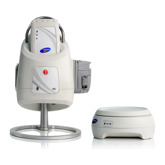
QUIPMENT HECKLIST The main components of the Goby™ system are the Urocap™ IV Uroflowmeter, the UDS Roam pressure recorder, and the Goby™ Hub. The following are required to setup the Goby™ system for Urodynamics: Standard Equipment Optional Equipment UDS Roam™... -
Page 22: Assemble Goby™ With Cart
3.2.2 Assemble Goby™ with Cart Follow the instructions provided to assemble the Goby™ with Cart: • Place the Goby™ Hub into the IV mount and lock in place using the gold screw. Clamp the mount on the IV pole at the desired height. •... -
Page 23: Assemble Goby™ On A Tabletop
Follow the instructions provided to assemble the Goby™ on a Tabletop: • Attach the foot mount onto the Goby™ Hub using the opening behind the power switch of the Goby™ Hub as the insertion point (Figure 7). Do not insert the foot into the other Goby™ Hub openings. -
Page 24: Assemble Goby™ On An Iv Pole
IV pole; place it on the center tube for increased stability. Tighten the thumbscrew to secure into place. Insert the Goby™ Hub into the clamp by sliding either the back or side mount on the Goby™ Hub into the slot of the clamp. -
Page 25: Set Up Infusion Transducer (Optional)
Hang the pressure cuff on the hook of the infusion transducer. SALINE BAG LABORIE recommends the positioning of the IV pole at least 30 cm above the patient table. 4. Inflate the pressure cuff to 300 mm Hg (when the green line appears on the pressure cuff gauge). -
Page 26: Set Up Ambulatory Remote Control (Optional)
NOTE: Be sure that the stopper cap is always securely in place whenever the stopcock position is being changed. CAUTION: AIR BUBBLES must not be present in the system during testing. Luer Lock Plug Pressure Cartridge Syringe Measurement Tubing MEDEX Transducer Figure 13: Fluid-Filled Pressure Transducer Setup LABORIE Goby Owner’s Manual GOBY-UM02... -
Page 27: Fluid-Filled Pressure Transducer Connections - Priming
Pves, reposition the Pabd catheter. Click the Equalize button on the UDS120 control panel. 11. Continue with the testing procedure when ready. IMPORTANT: Do not plug in or unplug any transducers when a procedure is running. Always stop the procedure before plugging in or unplugging transducers. LABORIE Goby Owner’s Manual GOBY-UM02... -
Page 28: Emg Patches
If you are already using the printer with a different type of connection, such as a USB connection, follow the instructions in Change the connection type on page 24 to set up the printer on your wireless network. LABORIE Goby Owner’s Manual GOBY-UM02... -
Page 29: Print Using Wi-Fi Direct
Click Device Setup & Software, and then select Connect a new device. d. When the Connection Options software screen appears, select Wireless. e. Select your HP printer from the detected printer list. Follow the onscreen instructions. 6. Print your document. LABORIE Goby Owner’s Manual GOBY-UM02... -
Page 30: Change The Connection Type
NOTE: A USB connection between the computer and printer can only be used if these two devices are isolated from the patient environment to reduce the risk of electric shock to the patient. LABORIE recommends that a wireless connection is used between the computer and printer at all times. -
Page 31: Figure 18: Launching Device Search
(Figure 20). Figure 20: Urocap Setup –Connected Device Manager 5. Click OK to go back to the Goby™ window. 6. Repeat the steps provided to connect the Goby™ Hub and the UDS Roam to the system. LABORIE Goby Owner’s Manual GOBY-UM02... -
Page 32: Figure 21: Finalizing Connection In The Device Manager
When all devices are connected and functioning, the Goby Device Manager window will look similar to Figure 22: Figure 22: Goby Device Manager Window IMPORTANT: Do not plug or unplug devices, pair or unpair Bluetooth devices, while the Goby system is in use with a patient. -
Page 33: Equipment Status Indicators And Buttons
Once the components are assembled and plugged in, the LED lights on the UDS Roam™, the Urocap™ IV, and the Goby™ Hub will flash their connection status. The LED lights for each device are located on the front of the device. The status is also displayed in the Device Manager. -
Page 34: Icon Indicators
NDICATORS Icon indicators in the Goby Device Manager window will display the status of a device in addition to battery status. The battery status is shown as a LED icon in the center of the window. 4.2.1 Connection Status Table 2 provides an overview of the status icons provided in the Device Manager Window with instructions on how to... -
Page 35: Battery Status
To restart the connection, follow the steps provided in the Connect Goby™ Devices section on page 24. NOTE: If either the Urocap™ IV or the UDS Roam shutdown due to low battery while a test is in progress, the graph will stop scrolling and an event Urocap™... -
Page 36: Device Connectors And Buttons
EVICE ONNECTORS AND UTTONS Connections ports and buttons at the bottom of the Goby™ Hub and Urocap™ IV provide different functions. Refer to Figure 23 and Figure 24. Infusion Transducer UPP connector UPP connector: plug the UPP cable into this port. -
Page 37: Software Features And Functions
Menu Bar: Click to access the features available for testing and analysis. The menus in the menu bar at the top of the Goby™ software window contain items that allow you to view saved test files, customize the appearance of the control panel, create custom configurations, and view test summaries. The Menu bar contains the File, Configure, Info, Options, Video, View Horizontal , and Calibration Sets menus. -
Page 38: Zoom Button On Control Panel
To bring back the channel, right-click anywhere on the graph and select Show Channels and then select the channel name to make it visible again (Figure 27). Note that the channel will appear at the bottom of the graph. Figure 27: Showing a Channel LABORIE Goby Owner’s Manual GOBY-UM02... -
Page 39: Modifying Channels
This feature displays the triangular channel value marker at the edge of the graph window to facilitate identification of the channel curve. The marker functions like a pen that draws the curves as the test is running. Figure 31: Channel Value Marker LABORIE Goby Owner’s Manual GOBY-UM02... -
Page 40: Drag/Drop Channel Ordering
4. Repeat steps 2-3 for other channels selected for re-ordering. 5. After all channels are re-ordered, right-mouse click in the channel information area to show the popup menu and deselect the Change Channel Order menu item. Refer to Figure 32. Figure 32: Reordering Channels LABORIE Goby Owner’s Manual GOBY-UM02... -
Page 41: File Menu
The File menu contains items that allow you to view saved files as well as contact information for the LABORIE support department. 5.3.1 Open Select File > Open to open and view any saved test files. Click on a patient name to view all tests associated with that particular patient. -
Page 42: Save As
Refer to Figure 36. NOTE: File Saving Directory can also be selected from Options > File Saving Directory. To avoid loss of data during a test, the Goby software automatically backs up test data every 1 minute. 5.3.5 Print Study Use this window to select the information to include in printed reports. -
Page 43: Print Setup
5.3.8 About UDS Client The About UDS Client dialog box displays the information for contacting LABORIE Technical Support as well as formulas used in Urodynamics. It also includes the software version number, the Firmware version number, and the device name. -
Page 44: Config Menu
• Scale (Min) Scale (Max) To change the Minimum and Maximum scale, click the box of a channel and type the desired value for the Min and the Max values. LABORIE Goby Owner’s Manual GOBY-UM02... -
Page 45: Upp Tab
2. Select the Distance Sensor Channel option (Figure 40). 3. Select Ch1 from the listing. 4. Click OK. NOTE: Make sure you first select the UPP test button on the Control Panel before setting up this feature. Figure 40: UPP Configuration Window LABORIE Goby Owner’s Manual GOBY-UM02... -
Page 46: Pump Tab
Stop • Slow • • Fast This option records events automatically when the pump runs or stops. Select the box to enable Auto Pump Event the feature. LABORIE Goby Owner’s Manual GOBY-UM02... -
Page 47: Filter Tab
Set the parameters for Uroflow such as auto Uroflow summary and auto printing under this tab. Figure 43: Configuration Window – Uroflow Tab Auto event settings may also be accesses through the Voiding Summary window. Refer to the Voiding Summary section on page 60. LABORIE Goby Owner’s Manual GOBY-UM02... -
Page 48: Arm Tab
Set the channels that correspond to Anorectal Manometry measurements under the Arm Tab. For more information on setting up and performing ARM tests with the Goby system, please refer to the ARM Owner’s Manual. NOTE: select the Enable Reverse Pump option to activate the reverse pump button on the control panel. -
Page 49: Ilist™ Events Linking Tab
Use the iList Events Linking tab to view available events. Follow the instructions below to review event availability in the Event Summary: 1. In the Goby software click Config > Set up/Modify. 2. Click the ILIST™ Events Linking tab. -
Page 50: Info Menu
Sq.Root Bladder Volume: automatically sets the ideal pump filling rate based on EBC value. NOTE: To enable pediatric pump settings, select the test configuration (.cfg) file first then enter patient information. MPUR and Sq Root Bladder Volume fill rates can then be selected for the test. LABORIE Goby Owner’s Manual GOBY-UM02... -
Page 51: Volume Warning Limit
The URA index is the y-intercept (Pdet intercept) of the following equation: Pdet* = URA= at Maximum flow Where: d = 3.8 x 10 Q = maximum flow Pdet = Detrusor pressure Pdet* = Detrusor pressure at maximum flow LABORIE Goby Owner’s Manual GOBY-UM02... -
Page 52: Figure 48: Ura Plot Window
2. Double-click in the text box of the name, threshold, or scale to be changed. 3. Type the appropriate modification. 4. Repeat steps 2 and 3 until all parameter changes are complete. 5. Click OK to exit. LABORIE Goby Owner’s Manual GOBY-UM02... -
Page 53: Linpurr
Abrams/Griffiths. This representation is also in an X-Y format; however, the Flow and Pdet channels are plotted on the Y- axis and X-axis respectively. To access the Parameters for the LinPURR graph: Click Options from the LinPURR window. The LinPURR Options box will appear. Figure 51: LinPURR Options Box LABORIE Goby Owner’s Manual GOBY-UM02... - Page 54 To Save the information for printing: Click Save Diagnosis. The numerical results of the LinPURR calculation will appear in the info-Diagnosis section of the software. • Click the Exit! button to close the LinPURR Summary. • Click the Exit! button in the LinPURR plot window to close the LinPURR Plot Window. LABORIE Goby Owner’s Manual GOBY-UM02...
-
Page 55: Bladder Work Function (Wf)
Residual volume is the difference between the inflow and the outflow. It is automatically calculated and is displayed in the Residual Volume text box. Refer to Figure 53 above. LABORIE Goby Owner’s Manual GOBY-UM02... -
Page 56: Chess
Click Info > X-Y Plot > ICS Nomogram (URA). Select Info > X-Y Plot > CHESS. The CHESS Classification Scheme window will appear (Figure 54). Click OK to exit. Figure 54: CHESS Classification Scheme Window LABORIE Goby Owner’s Manual GOBY-UM02... -
Page 57: Siroky Nomogram
The Siroky Nomogram was developed to provide an accurate and reliable indication of outflow obstruction. The UDS software provided by LABORIE will help the operator to compare the results of a patient’s pre-therapy and post-therapy Uroflow test. To view the Siroky Nomogram click Info > X-Y Plot > Siroky Nomogram. -
Page 58: Liverpool Nomogram
3. Select the Static and the Stress UPP portions of the graph. 4. Click OK. The Eberhard window opens to display the curves along with Total Urethral Length, Pressures, Functional Urethral Length, and change information. LABORIE Goby Owner’s Manual GOBY-UM02... -
Page 59: Pressure Transmission Ratio
2. Select Basic PTR in the Pressure Transmission window and click OK. The PTR Segment Selection box will appear (Figure 59). Figure 59: Basic PTR - PTR Segment Selection Box 3. Verify that the entire test is selected as a segment and click Confirm. LABORIE Goby Owner’s Manual GOBY-UM02... -
Page 60: Manual Ptr
NOTE: If more than one cough point exists in a study, LABORIE recommends to select separate segments instead of the entire test. Basic PTR allows the selection of up to three segments. 4. To modify selected segments, perform one of the following options in the PTR Segment Selection window then click Confirm: a. -
Page 61: Events
To delete or rename an event on a graph, right-click on an event located on the graph and select the Delete or Rename Event option from the resulting menu as shown in Figure 61 below. Figure 61: Deleting and Renaming Events on the Graph LABORIE Goby Owner’s Manual GOBY-UM02... -
Page 62: Permission To Void Event
Calculated LPP event is also automatically added at the peak pressure value within the Stress Test segment along with the Stress Leak event. To view the calculations, click Info > Event Summary. Figure 64: Even Summary – Calculated LLP LABORIE Goby Owner’s Manual GOBY-UM02... -
Page 63: Area Under Curve
3. When applicable, click the Area End button to establish the end point of area calculation. 4. Complete the test and click Info > Event Summary to review the Area Start and Area End values. LABORIE Goby Owner’s Manual GOBY-UM02... -
Page 64: Event Summary
Add or Change Event Annotation 1. Highlight an event and click Annotate! 2. The Event Annotation window will load. Type the text in the text box or pick from the list. 3. Click OK. Figure 69: Event Annotation Window LABORIE Goby Owner’s Manual GOBY-UM02... -
Page 65: Deleting Events From The Event Summary
Select All! All events will be selected as shown in the Printable column where all boxes will be checked. To select specific events for inclusion, click on check box in the Printable column. To exclude all the events from the printout, click UnSelect All!. Refer to the Printable column of Figure 68. LABORIE Goby Owner’s Manual GOBY-UM02... -
Page 66: Voiding Summary
Click Info from the menu bar and select Voiding Summary. The Voiding Summary printout supplies a comparison to the Nomogram tables (Figure 71). They are provided for both male and female patients on the same printout. Figure 71: Voiding Summary Window LABORIE Goby Owner’s Manual GOBY-UM02... -
Page 67: Uroflow Options Dialogue Box
Threshold: The minimum flow rate value used in calculating the Voiding Summary. Anything below this threshold is considered noise or insignificant flow. • Enable Artifact Recognition: Select check box to enable. • Artifact Recognition Threshold: Indicates the maximum acceptable change in Flow (acceleration) that is physiologically possible. LABORIE Goby Owner’s Manual GOBY-UM02... - Page 68 Example: If a patient kicks the transducer, the curve indicates a very high spike. The height of the spike is “unnaturally” high and therefore the UDS120 GOBY software recognizes the event as a deviation from what it considers a normal reading.
-
Page 69: Pediatric Nomogram
NOTE: This feature is available only if the patient is between 3 to 16 years of age. To access the Pediatric Nomogram Feature: 1. Click Pediatric Nomogram in the Voiding Summary window. The Pediatric Nomogram window will appear (Figure 73). LABORIE Goby Owner’s Manual GOBY-UM02... -
Page 70: Upp Summary
UPP Summary window represents a segment of the UPP test. From Pull start to Pull stop is one UPP segment or Pull 1. Additional Pulls are recorded in their own sequentially named columns. Figure 74: UPP Summary Window LABORIE Goby Owner’s Manual GOBY-UM02... -
Page 71: Re-Marking Upp Segments
(where X is the Pull #). The first UPP pull will be assigned number 1 with each additional Pull assigned a sequential number. UPP events for the first Pull will then be named UPP Start 1, UPP Peak 1, and UPP Stop 1 automatically (Figure 75). Figure 75: Urethral Pressure Profile Test LABORIE Goby Owner’s Manual GOBY-UM02... -
Page 72: Figure 76: Upp Segments Menu
Uncheck the UPP pull requiring re-marking and the event markings corresponding to that UPP pull will be removed from the graph. Figure 77 shows the removal of event markings for UPP1. Figure 77:UPP Segment Window – Removing UPP Events LABORIE Goby Owner’s Manual GOBY-UM02... -
Page 73: Figure 78: Marking Aupp Segment
NOTE: Used segments are indicated by a check mark beside the segment name. Figure 79: Adding the UPP Segment 5. Verify the UPP Summary (found under the Info menu) is updated with the newly marked UPP pull information. Figure 80: UPP Summary – Updated Segment LABORIE Goby Owner’s Manual GOBY-UM02... -
Page 74: Bladder Compliance (Optional)
6. To undo changes, deselect any segments and click Cancel. All changes are discarded, and the Compliance Measurement Range window will close. 7. To add additional segments for Bladder Compliance calculation, select a new segment name (ex. Segment 2) and repeat the procedure. LABORIE Goby Owner’s Manual GOBY-UM02... -
Page 75: Figure 82: Compliance Window
Average from Event – Compliance segments are created from the test event selected from the dropdown menu. Once the calculation start event is selected in Auto Compliance Method, select calculation end events using the Select Compliance Events menu. LABORIE Goby Owner’s Manual GOBY-UM02... -
Page 76: View Horizontal Menu
5.8.3 Uroflow Auto Start Another method of starting a test using the Goby™ is selecting the Uroflow Auto Start option. It enables the recording process as soon as the Urocap™ IV detects the first flow of data. This selection is appropriate for Uroflowmetry studies in instances where the patient requires privacy before and during Micturition. -
Page 77: Digital Value Indicator
3. Click the down arrow of the Current Row field to move to the second row of buttons. Repeat configuration steps until Label, Definitions, and Command type fields are set for all Control Panel buttons. 4. Click OK when all buttons are configured. LABORIE Goby Owner’s Manual GOBY-UM02... -
Page 78: Multiple Control Panel Sets And Hot Key Configuration
First Sensation button. 4. Click OK. Mark the event during a test using either the control panel button or the shortcut key. Figure 85: Properties Window LABORIE Goby Owner’s Manual GOBY-UM02... -
Page 79: Add An Image To A Control Panel Button
5. Click OK on the Properties window, and then click OK to close the Command window. The image will now appear in the button on the control panel as shown in Figure 88: Before After Figure 88: Edited Uroflow Button LABORIE Goby Owner’s Manual GOBY-UM02... -
Page 80: Customize Colors And Fonts And Adjust Button Size
The Button Height slider on the Command window can be used to adjust the size of the buttons in the Control Panel. Slide it to the right to increase the size of the button (Figure 86). LABORIE Goby Owner’s Manual GOBY-UM02... -
Page 81: Types Of Control Panel Commands
5.8.6.4 Types of Control Panel Commands The following table lists the types of control panel buttons available for the Goby™ software. Note that the button names (labels) in the chart are suggestions and can be re-named. Button Label Definition Type... -
Page 82: Figure 90: Command Window - Selecting Plots
When a UPP Command is selected in the Label drop down list and the definition is either PU or IN, a pop-up box appears for selection of the intervals at which the puller will stop. • Click OK to set the interval. Table 7: Control Panel Commands LABORIE Goby Owner’s Manual GOBY-UM02... -
Page 83: Enable Button Sounds
5. Once the color is selected, click Close to exit Event Properties and then click OK to close the Event Display Options window. During the next test the graph will display a colored background where the events occur. LABORIE Goby Owner’s Manual GOBY-UM02... -
Page 84: Auto Mark Peaks
It is recommended to zero all transducers before performing a test. To Set Zeroes before performing a test: • Select SET ZEROES! from the Menu Bar in the Goby Software window (Figure 25). The Set Zeroes window will launch (Figure 93). To set all transducers to zero, click All. -
Page 85: Video Menu
IDEO The Goby software has the capability to capture live images and videos of the functions of the bladder and the events that occur during a test. Use the video functions with an x-ray machine to view a live image of the test. For information on how to use the Video software and its functions, please refer to the Uropix Owner’s manual included with your system. -
Page 86: How To Run Tests
6 HOW TO RUN TESTS This section provides instructions on how to run tests with the GOBY™ System. For more information on equipment or accessories setup, refer to the Set Up Goby™ Equipment and Accessories section on page 15. ROFLOW A Uroflow test is a measurement of the rate at which urine flows out of the body. -
Page 87: Cmg/Pf Test
Turn on the computer and the printer. Start the UDS120 GOBY software. b. Turn on the Goby™ Hub with the power switch located at its base and ensure it is connected in the software. Ensure the UDS Roam™ and Urocap™ IV are connected to the software and at full battery. -
Page 88: Cmg/Pf Test Using Fluid-Filled Catheters
Turn on the computer and the printer. Start the UDS120 GOBY software. b. Turn on the Goby™ Hub with the power switch located at its base and ensure it is connected in the software. Ensure the UDS Roam™ and Urocap™ IV are connected to the software and at full battery. -
Page 89: Run Aupp Test
Turn on the computer and the printer. Start the UDS120 GOBY software. b. Turn on the Goby™ Hub with the power switch located at its base and ensure it is connected in the software. Ensure the UDS Roam™ and Urocap™ IV are connected to the software and at full battery. -
Page 90: Ambulatory Monitoring
1. Plug the Ambulatory Remote into Channel 4 (P4) of the UDS Roam™. 2. Double-click the UDS Roam icon in the main window to open the Goby Device Manager window: Figure 95: Goby Device Manager Window – Calibrate Remote Control and UDS Roam 3. -
Page 91: Part 2: Configure File Settings For Remote Detection Algorithm
6. On the graph, right-click on the first event to open the context menu as shown in Figure 99. Click Calibrate Remote Button Events > Button (1) from the context menu. Repeat for all other buttons using their correlating events. Figure 99: Calibrate Remote Button Events LABORIE Goby Owner’s Manual GOBY-UM02... -
Page 92: Part 3: Configure The Buttons
A printable copy of the remote button functions screen is available in the PDF document found on the LABORIE software disc. Write in the name of the event next to each button to help keep track of which event is configured for each button. -
Page 93: Figure 102: Ambulatory - Pretest Window
7. Ensure catheters are inserted as per the T-DOC Air-Charged Catheter and Transducer Setup section on page 21. LABORIE recommends the use of T-DOC Air-Charged for Ambulatory Monitoring to allow for freedom from the Urodynamic System. With transducers in the open position, Set Zeroes to atmospheric pressure. The test... -
Page 94: Print A Test
To select a report template, click the name in the Report(s) Selector and select an option from the drop-down menu. Figure 104: iList Reporter – Report Template To print a report, click the Print icon on the toolbar in the iList™ Reporter software. LABORIE Goby Owner’s Manual GOBY-UM02... -
Page 95: Calibration
Make sure the cart is on a level surface and the wheels are locked. The power switch for the Goby™ Hub is located at the bottom of the Hub. For an overview of connections for the Urocap™ IV and the Goby™ Hub see the Device Connectors and Buttons section on page 30. -
Page 96: Calibrate The Pump
Goby Device Manager window (Figure 108). Figure 108: Access Goby Device Manager – Goby™ Hub 3. Click the Setup button to launch the Goby Hub Setup window. Click the Device Calibration button (Figure 109). Figure 109: Goby Hub Setup Window 4. -
Page 97: Calibrate The Uds Roam™ For Emg, Pressure Transducers, Ambulatory Remote, And/Or Accutak
EMOTE CCUTAK 1. Switch ON the Goby™ Hub . 2. Start the UDS120 Goby software and double-click the UDS Roam™ icon in the main window to open the Goby Device Manager window (Figure 111). Figure 111: Access Goby Device Manager – UDS Roam™... -
Page 98: Calibrate The Infusion Transducer
1. Plug the infusion transducer cable into the connector at the bottom of the Goby™ Hub. 2. Switch ON the Goby™ Hub. 3. Start the UDS120 Goby software and double-click the Goby™ Hub icon in the main window to open the Goby Device Manager window (Figure 108). -
Page 99: Quick Reference And Faq
See the Battery - CHARGING and Preventative Maintenance section on page 10 for information about charging the devices. Can I still use the device(s) while the battery is charging? Yes, the Urocap™ IV and the UDS Roam™ can still be used while charging. LABORIE Goby Owner’s Manual GOBY-UM02... - Page 100 How do I stop the pump? Press the grey button on the front of the Goby™ Hub if you need to stop the pump at any time during a test (). Alternatively, lift the pump head to release the tubing from the pump.
-
Page 101: Software
24 to connect the devices. If reconnection is not successful, restart the computer and try the reconnection steps again. How do you connect to the Goby™ system after unplugging and then plugging back in one of the devices? Do I need to re-start the computer? Re-starting the computer is not required. -
Page 102: Troubleshoot
Devices not connected Connect the devices to the system. in software? Refer to the Connect Goby™ Devices section on page 24 for more information. Bluetooth devices Reconnect the devices as described paired/unpaired or on page 24. - Page 103 Uroflowmeter signal does not respond? Urocap™ IV improperly Connect the Urocap™ IV to the system. See page See the Connect connected? Goby™ Devices section on page 24 for more information. Uroflowmeter signal shows vibration and/or spike Plastic beaker is Reposition the Uroflowmeter and re-...
- Page 104 BLUETOOTH CONNECTION Unable to connect via Bluetooth? Connection broken? Bluetooth must be turned on by clicking the device icon in the Goby Device Manager. Reduce the distance between the device and the computer. The maximum distance between the processor and the computer is up to 10 meters (33 feet).
- Page 105 Symptom(s) Possible Cause(s) Check/Corrective Action(s) Received following message when the software Software opened too Close the Goby Device Manager and opens: soon after computer the UDS120 Goby software. Wait one turned on? minute and then re-open the Device Manager and the software to re- connect.
-
Page 106: Table 8: Troubleshooting
If problems continue, contact the LABORIE Service team at 1-800-333-1039 or email service@laborie.com. NOTE: The LABORIE Goby CT and CT PC are designed to be used as stand-alone cart systems, with the only mains power supply connection going through the LABORIE medical-grade power supply (LIT) in the base of the cart. Do not connect it to any other devices unless the whole system is outside the patient environment or the other device has its own medical grade power supply. -
Page 107: Appendices
CAR1002) CAR1002 Dimensions: 28.5”(72.4cm) L X 25.4”(64.5cm) W X 59.4”(150.9cm) H CAR1002 Weight: 56kg NOTE: CAR1000 is applicable to Goby™ CT cart configuration. CAR1002 is applicable to Goby™ CT PC cart configuration. Contact LABORIE for more information on Goby System configurations. -
Page 108: Classifications
Protects equipment from the harmful effects of water splashing from any direction (signified by the rating code 4). NOTE: the IP rating will be visible on the device label per uroflometer model. Table 11: GOBY™ Classifications LABORIE Goby Owner’s Manual GOBY-UM02... -
Page 109: Symbols And Labeling
IEC 60417 – Graphic Symbols for Use on Equipment. NOTE: Sterility symbols are applicable to consumbale devices only. Refer to consumable device instructions for use for complete symbol and instructional overview. Table 12: Symbols Glossary LABORIE Goby Owner’s Manual GOBY-UM02... -
Page 110: Table 13: Label Locations
Labels can be found on the devices as follows: Label Description Label Placement Goby Urodynamic Analyzer Systems Goby™ Hub, Wireless Pump & UDS Roam™ Docking Station UDS Roam, Wireless Battery Powered & EMG Measurement Device Table 13: Label Locations LABORIE Goby Owner’s Manual GOBY-UM02... -
Page 111: Electromagnetic Compatibility (Emc)
• Reorient or relocate Goby™ unit. • Increase the separation between Goby™ unit and the affected equipment. • Connect the non-medical system equipment into an outlet on a circuit different from that to which the Goby™ unit is connected. • Consult the dealer or experienced technical personnel for help. -
Page 112: Table 14: Table 1 Requirements
IEC 60601-1-2:2014 Table 1 Requirements The Goby Urodynamic Analyzer System is intended for use in the electromagnetic environment specified below. The customer or the user of the Goby Urodynamic Analyzer System should assure that it is used in such an environment. -
Page 113: Table 15: Table 2 Requirements
IEC 60601-1-2:2014 Table 2 Requirements: The Goby Urodynamic Analyzer System is intended for use in the electromagnetic environment specified below. The customer or the user of the Goby Urodynamic Analyzer System should assure that it is used in such an environment. -
Page 114: Table 16: Table 4 Requirements
FM radio broadcast and TV broadcast cannot be predicted theoretically with accuracy. To assess the electromagnetic environment due to fixed RF transmitters, an electromagnetic site survey should be considered. If the measured field strength in the location in which the Goby Urodynamic Analyzer System is used exceeds the applicable RF compliance level above, the Goby Urodynamic Analyzer System should be observed to verify normal operation. -
Page 115: Table 17: Table 6 Requirements
WARNING: Portable RF communications equipment (including peripherals such as antenna cables and external antennas) should be used no closer than 30 cm (12 inches) to any part of the Goby system, including cables specified by the manufacturer. Otherwise, degradation of the performance of this equipment could result. -
Page 116: Print Study Options
PRINT STUDY OPTIONS Click File Menu > Open > Print Test to access the Print Test window. Refer to the table below for an overview of the options available in in Goby UDS120 Software: Description Print Output Preferences: Uroflow Report 1-page voiding study report. -
Page 117: Nomogram Tables For Uroflowmetry
27.1 21.8 16.5 12.1 32.8 26.4 20.1 37.7 29.6 21.5 27.2 21.9 16.6 12.1 33.2 26.8 20.5 37.9 29.8 21.7 27.4 22.0 16.7 12.2 33.6 27.3 20.9 Table 19: Parameters of Uroflowmetry – 80 Males LABORIE Goby Owner’s Manual GOBY-UM02... -
Page 118: Table 20: Parameters Ofu
30.3 24.3 18.4 10.4 27.2 22.5 17.8 47.1 38.0 29.0 30.4 24.5 18.6 10.3 27.5 22.8 18.1 47.7 38.7 29.6 30.6 24.7 18.8 10.2 27.7 23.1 18.4 Table 20: Parameters of Uroflowmetry – 50 Females LABORIE Goby Owner’s Manual GOBY-UM02... -
Page 119: Calculations
ERMS SED IN RODYNAMICS ESTING NOTE: Notations in italics indicate usage specific to LABORIE’s Urodynamic testing protocols • abdominal pressure: (Pabd) the pressure surrounding the bladder, usually measured via rectum or vagina. o Standard channel on CMG or pressure/flow studies, measured in cmH2O •... - Page 120 This group sets standards for Urodynamic testing that all Laborie Medical training follows.
- Page 121 – Pdet. o Pves-Pabd=Pdet • terminal detrusor overactivity: a single involuntary detrusor contraction occurring at capacity, which cannot be suppressed and results in incontinence, usually resulting in emptying of bladder. LABORIE Goby Owner’s Manual GOBY-UM02...
- Page 122 Used to provoke stress incontinence, can be annotated as VLPP • voiding phase: (emptying phase) often used to describe the portion of a Urodynamic evaluation that records both pressures and flow parameters during a voiding event, this would immediately follow the “filling phase”. LABORIE Goby Owner’s Manual GOBY-UM02...
-
Page 123: Common Urodynamics Acronyms
LPP: Leak point pressure • LUTS: Lower urinary tract symptoms • MCC: Maximum cystometric capacity • MUCP: Maximum urethral closure pressure • MUP: Maximum urethral pressure • NGB: Neurogenic bladder Pabd Abdominal pressure • Pabd: Abdominal pressure LABORIE Goby Owner’s Manual GOBY-UM02... -
Page 124: References
A Cannon. AW Thomas, E Bartlett, J Ellis-Jones, L Chambers and P Abrams. BLADDER CONTRACTILICITY AND VOIDING EFFICIENCY IN MEN WITH BLADDER OUTLET OBSTRUCTION TREATED CONSERVATIVELY AND BY TURP. Bristol Urological Institute, Bristol, United Kingdom. Informally discussed posters, ICS 2000 Tampere. LABORIE Goby Owner’s Manual GOBY-UM02...
Need help?
Do you have a question about the Goby and is the answer not in the manual?
Questions and answers