Advertisement
Quick Links
INSTALLATION AND USER MANUAL FOR THE AB-Q-ST70 AUTO BIAS MODULE
Introduction:
This module has been designed to maintain a constant bias voltage through all power output tubes for
your ST70 stereo power amp.
The bias is kept at a constant level on the output tubes, irrespective of the signal level.
Please note. The preset bias level for this AB-Q module, see below for details, will differ depending on
whether your ST70 uses the EL34 power tubes.
6.3V AC windings for tubes are not grounded!
Benefits:
The advantage of using the AB-Q module is that it will extend output tube life, in a lot of cases it will also
improve the sound and last but not least, you will never have to worry about adjusting the bias again.
•
Instead of a pair of output tubes being biased together, now all four output tubes are
individually biased for greater control and stability
•
No need to keep an eye on and/or adjust the bias of the output tubes
•
Significant extension of the output tubes life
•
Bias is not influenced by the input signal
•
Undistorted and improved sound for a great listening experience
•
Reduction in hum and noise level of the amp
•
No maintenance or additional adjustments are required after the initial setup
•
Improved overall operation of the amp due to the reduction in the danger of a tube red plating
•
The AB-Q ensures that bias is kept at the pre-set value (see Initial Setup) even as the tubes age
•
The AB-Q comes with a soft start feature, which slowly brings up bias to each output tube
Quick Overview:
The AB-Q module has four
the correct level and that all is good with each tube.
Should any of these
blue
given output tube and that the tube in question needs to be immediately replaced.
When the amp is powered up, at first a
module. The
red
LED will go out after about 20s.
After a further delay of between 40-50s, each of the
now set and stable for each output tube. The amp is now ready to use.
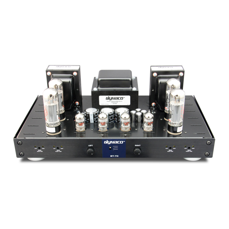
DYNACO ST-70 - DRIVER 6GH8 ECF82
blue
LED's, one for each output tube, which when lit, indicate that bias is at
LED's go out or not go on after power up, means that here is an issue with that
red
LED will be on, indicating that there is power to the AB-Q
blue
LED's should come on indicating that the bias is
Advertisement

Related Manuals for DYNACO ST-70


Summary of Contents for DYNACO ST-70
- Page 1 DYNACO ST-70 - DRIVER 6GH8 ECF82 INSTALLATION AND USER MANUAL FOR THE AB-Q-ST70 AUTO BIAS MODULE Introduction: This module has been designed to maintain a constant bias voltage through all power output tubes for your ST70 stereo power amp. The bias is kept at a constant level on the output tubes, irrespective of the signal level.
- Page 2 Preparing the ST70 for the installation of a new PC-3 driver and AB-Q module: You will need to remove the original 15.6 OHM cathode resistors and cathode connecting wires V2-V3 and V6-V7 according to the following photo.
- Page 3 1. Remove the four 15.6 OHM bias resistors marked Rcatch V 2 to Rcath V 6 and disconnected to wire cathodes V 2,3 to V 6,7 2. Install a new PC-3 driver board. The AB-Q module set also came with new spacers and screws. Use them to reinstall the new PC-3 driver and connect all the original wires to the numbered points on the driver.
- Page 6 7 and 17. If this does not happen, the PC-3 driver will fail and the signal will have significant distortion! 2. The AB-Q ST-70 module is already preset to a cathode current tubes EL34 of 38 mA. There is no need to set it again.
- Page 7 That’s it, you just set the AB-Q module to the desired bias operating level. For EL34 Vref= 0.380V. It is set without signal. Keep all of the above wires neat and tidy, maybe use zip ties to group them. This now pretty much completes the wiring of the AB-Q module to the ST70 driver PC-3 pcb and the power tubes.
- Page 8 Power down the amp and let everything cool down a bit then put the bottom chassis cover back on. Remove the dummy RCA plug. Place your ST70 amp in its spot, connect your speakers, RCA input and power lead to it and power the amp back up.
- Page 9 Output from signal inverter for EL34 - 86.8 Vpp. FFT synthesis - distortion: second harmonic frequency - 0.5%, third harmonic frequency - 0.4%...
Need help?
Do you have a question about the ST-70 and is the answer not in the manual?
Questions and answers