Advertisement
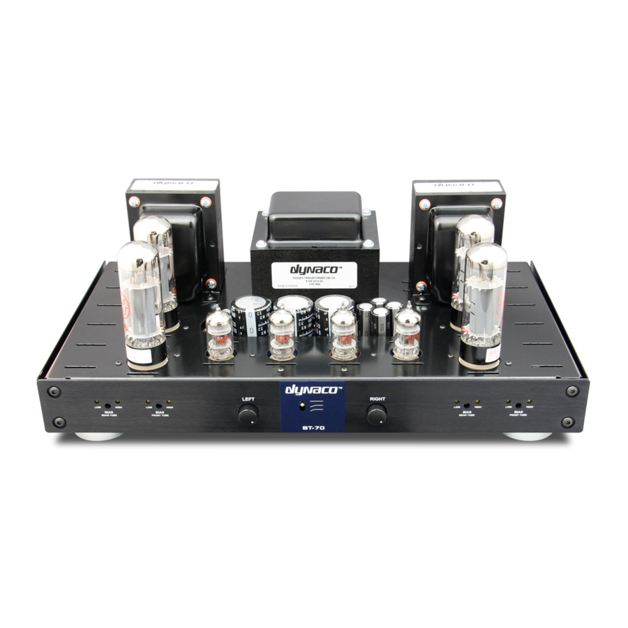
Dynaco ST-70 with VTA driver board Kit REBUILD assembly manual
In addition to the rebuild kit you will need
3 transformers (1 X PA-060 power transformer, 2 X A-470 output transformers)
* 1 VTA driver board and parts set
1 C-354 choke
4 X 1000 ohm resistors
the original 7 lug terminal strip
the dual .02 ceramic disk capacitor that was on lugs 5, 6 and 7 of the 7 lug terminal strip
2 grounding lugs
1 AC power cord
1 fuse post and fuse
1 rubber grommet
2 slide switches > 1 power switch, 1 stereo/mono switch
4 X EL34
* 3 X 12AT7
1 X GZ34 tubes
NOTE > Items marked with an asterisk are not found on an original ST-70
You may, as an option, paint your transformers for a better appearance with some type of
heat resistant paint. Recommended, are any type of paint used to paint automobile engine
blocks (engine enamel) or paint used to paint barbecue grilles. To most people a semi-gloss
paint looks best on transformers. Use a spray can – don't brush it on.
Recommended paints are Krylon BBQ and Stove paint (Krylon # 1618) OR any type of semi-
gloss automobile engine enamel in a spray can. This is usually carried by Wal-Mart and many
other stores. Go to an auto supply store for engine enamel.
1. Obtain SIX 8 X 32 machine screws 2 ½ to 3 inches long with nuts.
2. Remove one transformer 8 X 32 nut, nylon spacer(s) and screw and replace it with one
of the six machine screws and nut. Tighten the nut securely.
3. Do the same for the transformer screw on the opposite diagonal corner of the
transformer.
4. Remove the other two 8 X 32 screws, nylon spacers and nuts on that transformer.
5. Repeat steps 2 through 4 for the other two transformers.
6. Sand any imperfections in the factory paint off the three transformers with 100 grit
paper. Sand again with 220 grit paper
7. Remove all sanding dust from the outer surface of the transformer.
8. Cover the transformer wires by placing them in a plastic bag. Use some masking tape
near the transformer to hold the bag on the wires.
9. Spray 3 light coats on each transformer and allow to dry overnight.
10. Remove the plastic bags that cover the wires
11.
Reinstall all the original screws, spacers and nuts
Optionally painting the transformers
Bob01605@aol.com
order to complete the ST-70 assembly
in
.
Advertisement
Table of Contents

Related Manuals for DYNACO ST-70


Summary of Contents for DYNACO ST-70
- Page 1 * 3 X 12AT7 1 X GZ34 tubes NOTE > Items marked with an asterisk are not found on an original ST-70 Optionally painting the transformers You may, as an option, paint your transformers for a better appearance with some type of heat resistant paint.
- Page 2 INSTRUCTIONS NOTE – You may or may not want to construct the VTA driver board BEFORE or AFTER you attach the chassis parts. If you wish to construct the VTA driver board at this time skip ahead to the VTA driver board instructions which are inside the VTA package and proceed with its construction.
- Page 3 As with the original Dynaco manual, if you see the symbol “(S)” this means to solder that connection at that time. If the symbol is not there DO NOT SOLDER that connection at that time.
- Page 4 GREEN/WHITE wire from the RIGHT OUTPUT TRANSFORMER to pin 4 of V7. (S) 14. Connect one end of the Dynaco dual .02 Mfd capacitor to lug #7 of the seven lug terminal strip (S). Connect the middle wire of this capacitor to lug #6 of this terminal strip. Connect the remaining end of this .02 Mfd capacitor to lug #5 of the seven lug terminal strip (S).
- Page 5 19. Connect one end of a 5 ½ inch wire from lug 8 of V1 (S). Connect the other end of this wire to the quad cap filter capacitor 40 Mfd lug having the SQUARE symbol (S) 20. Connect one end of a short 2 inch jumper wire from the 80 mfd lug on the quad cap filter capacitor having the HALF-CIRCLE symbol (S).
- Page 6 5. Install the slide switch that fits into the stereo/mono slot with 4-40 hardware. This switch will NOT BE USED and NOT CONNECTED to the ST-70 circuitry in any way but it fills the front rectangular slot to give the front face of the amp a better appearance.
- Page 7 UNMARKED eyelets are set at a about a 45 degree angle to the sides of the board. Shorten the wires to proper length (S) 4. If you have original Dynaco A-470 transformers then add about 12 inches of wire to each YELLOW wire from each OUTPUT TRANSFORMER. (S). Insulate this connection. Shorten each wire appropriately and connect the extended YELLOW wire from the LEFT OUTPUT TRANSFORMER to the eyelet marked “NFB”...
- Page 8 UNMARKED eyelet near the left edge of the driver board about 7/8 inch from the BACK of the board. Do not press the wire in too deeply as it may short against the chassis below. (S) 6. Connect a 2 ½ inch wire from pin #6 of V6 (S) to the UNMARKED eyelet near the right edge of the driver board about 7/8 inch from the FRONT of the board.
-
Page 9: Other Notes
The Stereo/mono switch on the front has been bypassed for better sound. The input jacks connect directly to the driver board. Specifications of the ST-70 Amplifier with VTA Driver board Power output ..…… 35 watts RMS per channel at 1 KHz at 1% THD with both channels driven Frequency response . - Page 10 Voltage readings * Note # 1 – Make sure you have your meter set to AC or DC as mentioned below. Ground is any point on the chassis frame. Place the black or negative probe on the chassis and the red or positive probe on the point mentioned.
- Page 11 Bob01605@aol.com...
- Page 12 Bob01605@aol.com...
- Page 13 Bob01605@aol.com...
Need help?
Do you have a question about the ST-70 and is the answer not in the manual?
Questions and answers