Table of Contents
Advertisement
Advertisement
Table of Contents

Related Manuals for Dongbu Robot HERKULEX DRS-0101

Summary of Contents for Dongbu Robot HERKULEX DRS-0101
- Page 1 Version 1.00 DRS- 0101 / DRS- 0201 User Manual...
-
Page 2: Table Of Contents
ONTENT 1. Safety Instructions 1-1. Meaning of Symbols 1-2. Operating Precautions 1-3. Safe Battery Handling 1-4. Safe Storage 2. Introduction 2-1. Parts List 2-2. Product Overview 2-3. Specification 3. Assembly Instructions 3-1. Joint Assembly 3-2. Joint Assembly(Optional Bracket and Bolt Required) 3-3. -
Page 3: Safety Instructions
1. Safety Instructions Thank you for purchasing our HerkuleX. For your safety, please read the instruction manual before using the HerkuleX with particular attention to the safety instructions below. 1-1. Meaning of Symbols Any sections within the manual with the following symbols require special attention to safety. Ignoring the instructions with this symbol can lead to serious bodily Danger injury or death to the user and to those near by and high possibility... -
Page 4: Safe Battery Handling
Keep away from water, sand, and dust. Do not use the servo for purposes other than installation in the indoor robot. Do not use overt force to turn the servo horn. Servo should not be left if locked position. 1-3. Safe Battery Handling Warning Alwasy use the appropriate battery charger to charge the battery pack. -
Page 5: Introduction
2. Introduction 2-1. Parts List Servo : 1ea Horn : 1ea Horn Bolt(BHT 2.6X8) : 1ea Wheel Horn Bushing : 1ea Wheel Horn Washer : 1ea Wheel Horn Bolt(PHM 3X8) : 1ea Cable Guard : 2ea I-type Joint : 2ea L-type Joint : 2ea L-type Joint(Single Nut) -
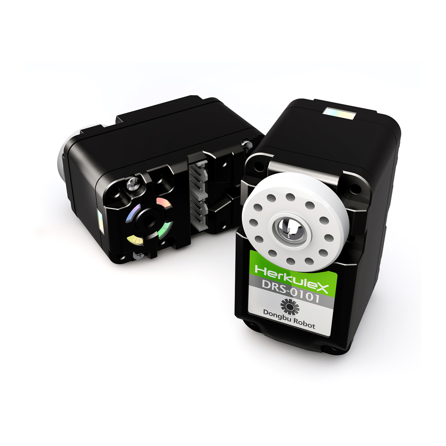
Page 6: Product Overview
2-2. Product Overview Smart Servo DRS-0101 and DRS-0201 are state of the art modular smart servos incorporating motor, gear reducer, control circutry and communications capability in one single package. Both servos are capable of detecting and responding to internal changes in termerature and voltage supply. - Page 7 Durability Manufactured using Super Engineering Plastic, our servos are highly durable, impact resistant and designed to withstand even the high torque stress levels that go beyond the tolerance specs of Engineering Plastic Gears. Communication Using Multi Drop TTL Full Duplex UART Serial communications protocol with maxium speed of 0.667Mbps, single command can set the speed, position, LED, operational compliance, stop and operational status of up to 254 servos simultaneoulsy at once.
- Page 8 Self Diagnosis Servos are capable of diagnosing seven different types of errors which are then indicated by the LED. Servo UI is used to set the function and timing of the Overload Protection. ( protects the servo when the overload occurs by releasing the torque ) Multi Drop Network Expandable Multi Drop type Network with 1:n configuration.
-
Page 9: Specification
2-3. Specification 45mm(W) x 24.0mm(D) x 31mm(H) / 45g [1.59 oz] Dimension / Weight 45mm(W) x 24.0mm(D) x 31mm(H) / 60g [2.12 oz] (DRS-0201) [1.77 in.(W) x 0.94 in.(D) x 1.22 in.(H)] Reduction Ratio 1 : 266 Gear Material Super Engineering Plastic, Heavy Duty Metal (DRS-0201) 7~12VDC(Optimized 7.4V) Input Voltage 450mA @ 7.4V : 1.7kgf.cm, 670mA @ 7.4V : 2.2kgf.cm (DRS-0201) -
Page 10: Assembly Instructions
3. Assembly Instructions 3-1. Joint Assembly TYPE 1 Assembly Diagram Assembled Unit TYPE 2 Assembly Diagram Assembled Unit... - Page 11 TYPE 3 PHM 2X4 (Option) Bracket (not included) Bracket (not included) Assembly Diagram Assembled Unit TYPE 4 PHM 2X4 (Option) Bracket (not included) Bracket (not included) Assembly Diagram Assembled Unit TYPE 5 Assembly Diagram Assembled Unit...
-
Page 12: Joint Assembly(Optional Bracket And Bolt Required)
3-2. Joint Assembly (Optional Brcket and Bolt Required) TYPE 1 PHM 2X4 (Option) 별매 Assembly Diagram Assembled Unit Assembly Diagram Assembled Unit Assembly Diagram Assembled Unit... - Page 13 TYPE 2 Assembly Diagram Assembled Unit Assembly Diagram Assembled Unit TYPE 3 PHM 2X6 (Option) PHM 2X4 (Option) Assembly Diagram Assembled Unit Assembly Diagram Assembled Unit...
- Page 14 Assembly Diagram Assembled Unit TYPE 4 PHM 2X6 (Option) Assembly Diagram Assembled Unit Assembly Diagram Assembled Unit Assembly Diagram Assembled Unit...
- Page 15 Assembly Diagram Assembled Unit TYPE 5 PHM 2X6 (Option) Assembly Diagram Assembled Unit Assembly Diagram Assembled Unit...
- Page 16 TYPE 6 PHM 2X6 (Option) Assembly Diagram Assembled Unit Assembly Diagram Assembled Unit TYPE 7 PHM 2X6 (Option) Assembly Diagram Assembled Unit...
-
Page 17: Connector Pin & System Assembly
3-3. Connector Pin & System Assembly All the Servo to Servo connectors have same Pin assingment as the diagram below. Multi Drop Network makes expansion easy. Controller RS232 Cable Controller Pin # Description RS232 Cable 232 Gender Caution Servos must be cross connected to the PC or Motion Controller. Examples of cross connection would be Servo TXD to PC or Motion Controlller RXD, Servo RXD to PC or Motion Controller TXD. -
Page 18: Operation
4. Operation 4-1. Communications Protocol Introduction Servo Controller communicates with the servos in the network by sending a Request Packet and receiving ACK Packet back from the servo. The example below shows the controller sending a Request Packet to the Servo n and receiving ACK packet back from the Servo n. Regardless of the number of servos in the network, only the servo with correct ID (n) will acknowledge the Request Packet and send the ACK Packet to the controller. - Page 19 Header Indicates start of the Packet. Header Type Value 0xFF 0xFF Byte Packet Size Refers to total Packe size ( in Bytes ) from Header to Data. The maximum Packet Size 233, if the packet size is larger than 223 Bytes, packet may not be recognized. Minimum packet size is 7 which is packet without any data.
- Page 20 Check Sum1 Check Sum1 is used to check for errors in the Packet. Check Sum1 is calculated as follows, Check Sum1 = (PacketSize ^ pID ^ CMD ^ Data[0] ^ Data[1] ^ …… ^ Data[n]) & 0xFE. Header, Check Sum1, Check Sum2 are not included in the calculation. ※...
-
Page 21: Register Map
4-2. Register Map Register Map are values residing within the Servo and contain data pertaining to current servo status and operation. Registers are either Non-Volatile or Volatile. Users are able to control the servos by using Request Packet and ACK Packet to either check or change the data in the Register Map. - Page 22 ADDRESS Type Bytes Default Valid Range Description Baud Rate 0x10 Refer to Pg 26 Communication Speed Reserved Reserved 0x00 Servo ID(0xFE : Can be used as 0xFD 0x00 ~ 0xFD Broadcasing ID. ID not assignable) 0x01 0x00 ~ 0x2 Refer to Pg 33 ACK Policy 0x7F 0x00 ~ 0x7F...
- Page 23 ADDRESS Type Bytes Default Valid Range Description Overload Check Interval Overload Detection Period 0x96 0x00 ~ 0xFE 11.2ms/Tick, 0x96 : 1.68s Stop Threshold 0x03 0x00 ~ 0xFE Stop Threshold Inposition Margin 0x03 0x00 ~ 0xFE Offset Threshold Reserved Reserved Reserved Reserved Calibration Difference -128 ~ 127...
- Page 24 Volatile Register(RAM Register) MAP Volatile Memory has direct affect on the operation of the Servo and reverts to default (EEP Register) value when the Servo is reboot even though RAM register value has been changed to change the servo operating parameters. Read/Write has to be performed to RAM Register value to operate the Servo, change the operating parameters or to check servo status.
- Page 25 ADDRESS Type Bytes Valid Range Description ADC Fault Temp/Voltage error check interval 0x00 ~ 0xFE Detection Period 11.2ms/Tick, 0x2D : 504ms Packet Error check interval, Packet Garbage 0x00 ~ 0xFE Detection Period 11.2ms/Tick, 0x12 : 201ms Stop detection check interval, Stop Detection Period 0x0000 ~ 0x7FFF 11.2ms/Tick, 0x1B : 302ms...
- Page 26 Register Detail Type Bytes EEP ADDR RAM ADDR Description Model No1 Servo Model Name Model No2 Version1 Firmware Version (※ for DRS-0201, Model No1 is 0x02) Version2 Default Baud Rate is 115,200bps 0x02 : 666,666bps 0x03 : 500,000bps 0x04 : 400,000bps Baud Rate 0x07 : 250,000bps 0x09 : 200,000bps...
- Page 27 구분 Bytes EEP ADDR RAM ADDR Description Acceleration ratio regarding velocity Profile Ratio of operation time of Motion command (I_JOG, S_JOG), % Acceleration ratio is same as decceleration ratio Maximum r(Acceleration Ratio) value is 50 Ex) When operating time is 100ms and r(Acceleration Ratio) is 20 : Acceleration Acceleration Ratio time is 100 X 0.2 = 20ms...
- Page 28 Type Bytes EEP ADDR RAM ADDR Description Position Kp Proportional Gain Position Kd Derivative Gain Position Ki Integral Gain Position Feedforward 1st Gain Refer to Pg 35 Position Feedforward 2nd Gain Refer to Pg 35 Reserved Reserved Reserved Reserved Alarm LED blink period according to LED Blink Period policy 11.2ms Temp/Voltage error check interval...
- Page 29 Type Bytes EEP ADDR RAM ADDR Description Servo LED control When corresponding Bit value 1 = On, 0 = Off (0x01 : Green, 0x02 : Blue, 0x04 : Red) LED Control ※ When alarm LED activated by r(Status Error) and r(Alarm LED Policy). r(Led Control) Write value ignored Voltage Input Voltage = 0.074 X ADC...
- Page 30 Acceleration Ratio(RAM Register Address 8) Acceleration Ratio is controlled by changing the parameter value and any change in the acceleration ratio is applied to the decceleration ratio by exactly the same amount. The default Acceleration Ratio parameter shows a trapezoidal type speed profile. ※...
- Page 31 0x02 : Blue 0x04 : Red ※ Whe Alarm LED is activated by the r(Status Error)or r(Alarm LED Policy), value in r(LED Control) is ignored. Voltage(RAM Register Address 54) Shows the ADC(Analog Digital Conversion) value of the input voltage in raw data. The conversion formula to actual voltage is shown below.
- Page 32 Absolute Position(RAM Register Address 60) Shows uncalibrated current position in raw data. Relationshop between Raw Data and actual degree is as follows. Degree = Position Raw Data X 0.325 1002 (159.8 ˚ ) (-159.8 ˚ ) Recommended Range Full Range 1023 (166.7 ˚...
- Page 33 Play Time Absolute Goal Position Absolute Desired Desired Velocity Trajectory Position Time Time Command Command Current Current recevied recevied ACK Policy(RAM Register Address 1) Sets ACK Packet reply policy when Request Packet is received. 0 : No reply to any Request Packet 1 : Only reply to Read CMD 2 : Reply to all Request Packet ※...
- Page 34 Maximum Temperature(RAM Register Address 5) Maximum operational temperature shown in Raw Data. When internal servo temperature r(Temperature) exceeds r(Max Temperature), "Exceeded Temperature Limit" in r(Status Error) becomes active. Resulting Alarm LED and Torque status can be changed using r(LED Policy), r(Servo Policy). Default value is 0xDF(approximatley 85℃).
- Page 35 Maximum Position(RAM Register Address 22) Maximum operational angle in Raw Data. When requested position angle is greater than r(Max Position), "Exceed Allowed POT Limit" in r(Max Position) becomes active and the operation is limited to r(Max Position). Default value is 0x3EA(approximately 159.8˚). Refer to conversion chart in (Pg 53) for actual angle. Position Kp(RAM Register Address 24) Shows the Proportional Gain.
- Page 36 Stop Detection Period(RAM Register Address 41) Set time limit by which the servo stoppage is measured to determine if it has stopped. 1 is equivalent to 11.ms. If the servo stoppage lasts beyond the time limit, it is determined to be stopped. Default value is 0x1B ( Approximately 302ms ) Overload Detection Period(RAM Register Address 42) Set time limit by which the servo overload is measured to determine if the overload has occured.
- Page 37 PWM Offset(RAM Address 14) When the 0 point of the PWM is moved, PWM will increase output by the amount of the Offset. This output could be used to act as a compensator in a system where load is on one side ( Ex: Gravity ).
- Page 38 +PWM Dead Zone r(Saturator Offset) r(PWM MIN) +Position r(PWM MIN) Goal Position r(Saturator Offset) r(Saturator Slop)/256 -PWM +PWM +Position PWM limited by Dead Zone Goal Position Saturator Saturator output PWM -PWM Final output PWM PWM limited by Saturator Calibration Difference(RAM Register Address 47) Used to calibrate newtral point(standard).
- Page 39 Status Error, Status Details(RAM Register Address 48, 49) Status REG (Status Error) REG (Status Error) Bits Bits Bits Value Comment Bits Value Comment 0X01 Exceed Input Voltage limit 0X01 Moving flag 0X02 Exceed allowed POT limit 0X02 Inposition flag 0X04 Exceed Temperature limit 0X04 Checksum Error...
-
Page 40: Command Set
5. Command Set To control the Servo, CMD is sent to the servo from the Controller in Binary format. Our servos are controlled by 9 different CMDs. Once the Servo receives Request Packet with included CMD, Servo performs requested operation and returns the result to the Controller by ACK Packet. - Page 41 Type Explanation CMD(0x03) Reply Packet RAM_WRITE 0x43 Default is no reply, reply possible by changing r(ACK Policy) setting CMD(0x04) Reply Packet 0x44 RAM_READ May not reply depending on r(ACK Policy) setting. CMD(0x05) Reply Packet 0x45 I_JOG Default is no reply, reply possible by changing r(ACK Policy) setting CMD(0x06) Reply Packet 0x46 S_JOG...
-
Page 42: Command Examples
6. Command Examples 5-1. EEP_READ Request 4 Bytes of information from EEP Register 0x1E Address of Servo ID(253). 4 Bytes from EEP Register 0x1E Address are e(Position Kp)and e(Position Kd). Header Packet Size EEP_READ 0xFF 0xFF Servo ID 0x02 Example1 0xFF 0xFF 0x09(9) - Page 43 ACK Packet Header Packet Size Check Sum1 Check Sum2 EEP_READ ACK of Example1 0xFF 0xFF 0x0F 0xFD 0x42 0x4C 0xB2 Data Data[0] Data[1] Data[4] Data[5] Data[2] Data[3] Data[4] Data[5] (Address) (Length) (Status Error) (Status Detail) 0x1E 0x04 0xB8 0x01 0x40 0x1F 0x00 0x00...
- Page 44 6-3. RAM_WRITE Example 1 ID(253), r(LED Control), Address(0x35(53)) Request Green LED On. Example 2 ID(253), r(Status Error, Status Detail), Request to Clear Address(0x30(48)) to "0". Example 3 ID(253), r(Torque Control), Request to write 0x60 to Address(0x34(52)) for Torque On. ※ Make sure to haveTorque On before (I_JOG, S_JOG) command to avoid error. Header Packet Size Check Sum1...
- Page 45 RAM_READ ACK Reply to RAM_READ(CMD 0x04)with Packet, reply CMD is 0x44, last 2Bytes of All ACK Packet contain r(Status Error) and r(Status Detail). ACK Packet reply option can be changed by r(ACK Policy) Data[2] 0x01 is r(LED Control) value, it means Green LED is on. Data[3] Data[3] is Status Error: No Error, Data[4] 0x42 means Torque On and Inposition, Arrived at goal position.
- Page 46 Header Packet Size Check Sum1 Check Sum2 I_JOG 0xFF 0xFF 7+(5XI_JOG) Servo ID 0x05 (Refer to Checksum Formula) Example1 0xFF 0xFF 0x0C(12) 0xFD 0x05 0x32 0xCC Example2 0xFF 0xFF 0x0C(12) 0xFD 0x05 0x7E 0x80 Optional Data I_JOG_S(0) JOG(LSB) JOG(MSB) playtime 0x00 0x02 0x04...
- Page 47 Header Packet Size Check Sum1 Check Sum2 S_JOG 0xFF 0xFF 7+(5XI_JOG #) Servo ID 0x06 (Refer to Checksum Formula) Example1 0xFF 0xFF 0x0C(12) 0xFD 0x06 0x30 0xCE Example2 0xFF 0xFF 0x0C(12) 0xFD 0x06 0xFE 0x00 Optional Data S_JOG_S(0) PLAY TIME JOG(LSB) JOG(MSB) 0x3C(60)
- Page 48 I_JOG, S_JOG Packet Structure I_JOG_TAG S_JOG_TAG Information Information Type Comments Type Comments Bytes Bits Bytes Bits Case) JOG Case) JOG Desired Goal POS Desired Goal POS (Calibration applied) (Calibration applied) Case) Infinite turn Case) Infinite turn Desired PWM Desired PWM ※...
- Page 49 Header Packet Size Check Sum1 Check Sum2 STAT 0xFF 0xFF Servo ID 0x07 (Refer to Pg 20) Example2 0xFF 0xFF 0x07 0xFD 0x07 0xFC 0x02 STAT ACK 0xFF 0xFF 0x09 0xFD 0x47 0xF2 0x0C Optional Data Data[0] Data[1] 0x00 0x40 0x00 0x40 6-8.
- Page 50 6-9. REBOOT ID(254) Reboot REBOOT ACK When r(ACK Policy) is set to "2" meaning "Always Reply" Send ACK Packet Header Packet Size Check Sum1 Check Sum2 REBOOT 0xFF 0xFF Servo ID 0x09 (Refer to Pg 20) Example1 0xFF 0xFF 0x07 0xFD 0x09 0xF2...
- Page 51 Reference...
- Page 53 ADC Voltage Coversion Chart Decimal HEX Decimal HEX Decimal HEX Decimal HEX 0.000 4.741 9.481 14.222 0.074 4.815 9.556 14.296 0.148 4.889 9.630 14.370 0.222 4.963 9.704 14.444 0.296 5.037 9.778 14.519 0.370 5.111 9.852 14.593 0.444 5.185 9.926 14.667 0.519 5.259 10.000...
- Page 54 ADC Temperature Coversion Chart ℃ ℃ ℃ ℃ Decimal HEX Decimal HEX Decimal HEX Decimal HEX -79.47 1.37 29.33 68.32 -71.78 1.81 29.76 69.20 -63.20 2.24 30.18 70.10 -57.81 2.67 30.60 71.02 -53.80 3.10 31.03 4.137 -50.58 3.52 31.46 4.157 -47.86 3.94 31.89...
- Page 55 ADC Position Coversion Chart degree degree degree degree Decimal HEX Decimal HEX Decimal HEX Decimal HEX -166.650 -144.169 -121.689 -99.208 -166.324 -143.844 -121.363 -98.882 -165.998 -143.518 -121.037 -98.556 -165.673 -143.192 -120.711 -98.231 -165.347 -142.866 -120.385 -97.905 -165.021 -142.540 -120.060 -97.579 -164.695 -142.215 -119.734...
- Page 56 degree degree degree degree Decimal HEX Decimal HEX Decimal HEX Decimal HEX -76.727 -52.618 -5.376 -4.398 -76.402 -52.292 -5.050 -4.073 -76.076 -51.966 -4.724 -3.747 -75.750 -51.640 -28.508 -3.421 -75.424 -51.315 -28.182 -3.095 -75.098 -50.989 -27.856 -2.769 -74.773 -50.663 -27.531 -2.444 -74.447 -50.337 -27.205...
- Page 57 degree degree degree degree Decimal HEX Decimal HEX Decimal HEX Decimal HEX 19.711 43.821 67.931 92.040 20.037 44.147 68.256 92.366 20.363 44.473 68.582 92.692 20.689 44.798 68.908 93.018 21.015 45.124 69.234 93.344 21.340 45.450 69.560 93.669 21.666 45.776 69.885 93.995 21.992 46.102 70.211...
- Page 58 degree degree degree Decimal HEX Decimal HEX Decimal HEX 116.150 140.260 1016 164.369 116.476 140.585 1017 164.695 116.802 140.911 1018 165.021 117.127 141.237 1019 165.347 117.453 141.563 1020 165.673 117.779 141.889 1021 165.998 118.105 142.215 1022 166.324 118.431 142.540 1023 166.650 118.756 142.866...
Need help?
Do you have a question about the HERKULEX DRS-0101 and is the answer not in the manual?
Questions and answers