Advertisement
Quick Links
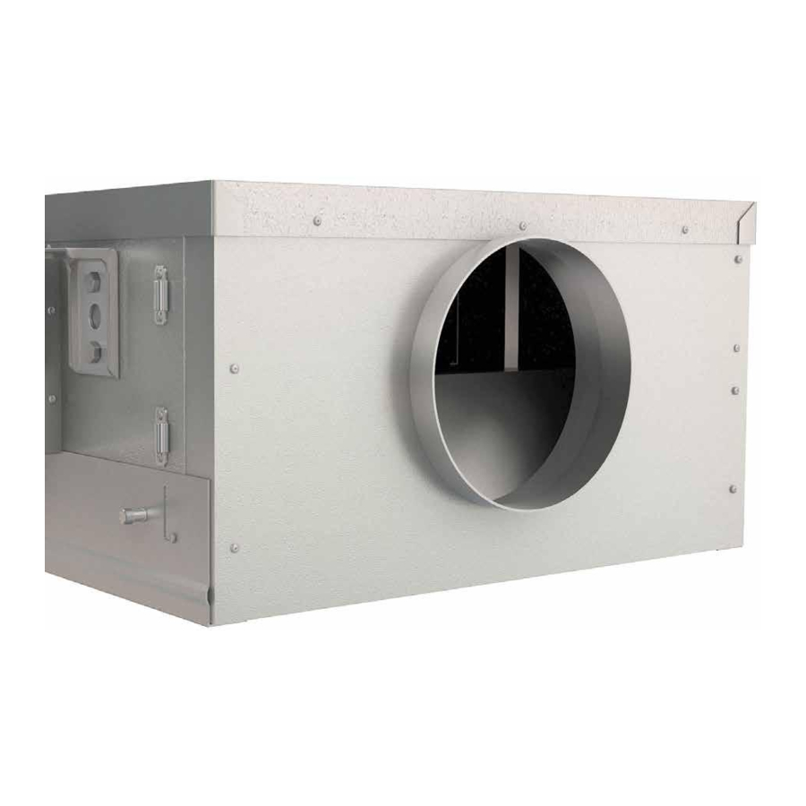
DAVE Extract Fans
The Dave range of in-line backward curve fans consisting of
9 duty sizes with a maximum of 1.1m
Units are manufactured from aluzinc, rectangular in section and have
circular rigid spigots at each end. All units are supplied with fixing
brackets designed to simplify installation.
1.0 Fan Unit Coding Descriptions
DE1-BC
| | | |
1 2 3 4
1. DAVE Range
2. Extract fan
3. Case: standard
size (1-7))
4. Control
BC = Basic control
2.0 Handling
Always handle the units carefully to avoid damage and distortion.
Care must be taken to ensure any slings used for hoisting do not
damage the casing or the control module components (BC models).
Note: The weight of the unit is on the rating plate.
Figure 1: Typical lifting methods.
Slings via spreaders fitted to unit
with base frame.
Please note that above images are
examples of typical lifting methods.
Actual unit lifting plan and risks
must be assessed by competent
personnel before moving the unit.
DAVE Extract Fans (BC Models)
For Internal and External use
Installation, Operating & Maintenance Instructions
3
/s (1100l/s).
DE4HA-BC
| | | | | |
1 2 3 4 5 6
1. DAVE Range
2. Extract fan
3. Case: size (1-7)
4. H = High pressure
fan (Size 2 & 4 only)
5. Extended case
6. Control
BC = Basic control
Forklift.
Assembly with
base frame.
Palletised.
Nuaire Limited Western Industrial Estate Caerphilly United Kingdom CF83 1NA
T: 029 2085 8400 F: 029 2085 8444 E: info@nuaire.co.uk W: www.nuaire.co.uk
3.0 Installation
Installation must be carried out by competent personnel, in
accordance with good industry practice, the appropriate authority
and in conformance with all statutory and governing regulations.
Access to the unit for maintenance is via the top or bottom lid,
therefore this should be taken into account before installation
takes place (See important note below).
Service/Maintenance Access – Unit must be installed with a
minimum of unit depth as additional clearance i.e DE1-BC
either allow 233mm above or below unit.
Dave extract fans can be installed in any orientation. Units are
supplied complete with four support mounting brackets for quick
and easy installation, either surface mounted or suspended with
drop rods.
Figure 2: Units supplied with four mounting brackets with
1 x M8 hole in each.
4.0 Motor Details
Unit Code
Voltage
phase
frequency
DE1-BC/DE1A-BC
230/1/50
DE2-BC/DE2A-BC
230/1/50
DE2H-BC/DE2HA-BC 230/1/50
DE3-BC/DE3A-BC
230/1/50
DE4-BC/DE4A-BC
230/1/50
DE4H-BC/DE4HA-BC 230/1/50
DE5-BC/DE5A-BC
230/1/50
DE6-BC/DE6A-BC
230/1/50
DE7-BC/DE7A-BC
230/1/50
O
O
60
C (sizes 1-5), 40
C (sizes 6-7) maximum permissable air temperature
passing over motor.
1
The EMC Directive
2004/108/EC
The Low Voltage
Directive
2006/95/EC
Input
Start
f.l.c.
Nominal
power
current (amps)
fan
(kW)
(amps)
speed
0.03
0.27
0.27
3770
0.088
0.75
0.75
3200
0.17
1.4
1.4
4060
0.17
1.4
1.4
2860
0.17
1.35
1.35
2550
0.49
2.2
2.2
3700
0.5
2.2
2.2
2250
0.45
2.9
2.9
1710
0.775
3.5
3.5
1650
09. 04. 15. Leaflet Number 671680
Advertisement

Subscribe to Our Youtube Channel
Related Manuals for NuAire DAVE


Summary of Contents for NuAire DAVE
- Page 1 | | | | | | 1 2 3 4 1 2 3 4 5 6 Dave extract fans can be installed in any orientation. Units are 1. DAVE Range 1. DAVE Range supplied complete with four support mounting brackets for quick 2.
- Page 2 Installation, Operating and Maintenance Instructions DAVE Extract Fans (BC Models) 5.0 Dimensions & Weights - DAVE Basic Control Extract Fans Fig 3: Example Code: DE2-BC Dimensions Extract fans with standard case Unit Code Standard ‘D’ Standard Case Case A DE1-BC...
- Page 3 230V ~ 50Hz <IV = fan off. Alternatively link from +V to SIG for max speed Isolation - Before commencing work make sure that the unit and Nuaire control are electrically isolated from the mains supply. 09. 04. 15. Leaflet Number 671680...
-
Page 4: Maintenance
Attenuation Pods (‘A’ models with extended case only) Attenuation Pods Retaining Clips (‘A’ models only) Isolation - Before commencing work make sure that the unit and Nuaire control are electrically isolated G3 Filter (‘A’ models with extended case only) from the mains supply. -
Page 5: Warranty
D6A-G3FILTERKIT DE7A D7A-G3FILTERKIT 11.0 Service Enquiries Nuaire can assist you in all aspects of service. Our Technical Support department will be happy to provide any assistance required. Telephone 029 2085 8400 Fax 029 2085 8444 09. 04. 15. Leaflet Number 671680... - Page 6 Where access to any part of equipment which moves, or can become electrically live are not prevented by the equipment panels or by fixed installation detail (eg ducting), then The equipment referred to in this Declaration of Incorporation is supplied by Nuaire to guarding to the appropriate standard must be fitted.
Need help?
Do you have a question about the DAVE and is the answer not in the manual?
Questions and answers