Advertisement
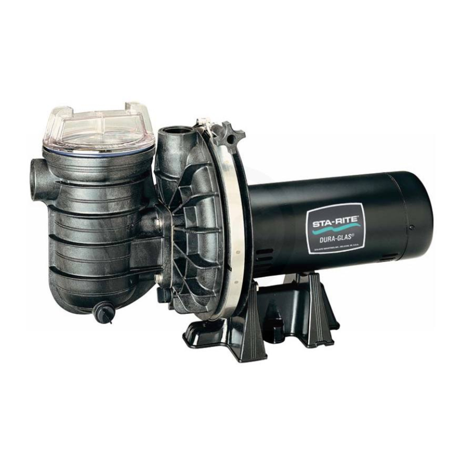
DURA-GLAS and MAX-E-GLAS
CENTRIFUGAL PUMPS with TRAP
Sta-Rite Pool/Spa Group
293 Wright Street, Delavan, WI 53115
North America: 800-752-0183, FAX 800-582-2217
International: 262-728-5551, FAX: 262-728-4461, TELEX: ITT 4970245
www.sta-ritepool.com
Union City, TN • Delavan, WI • Mississauga, Ont. • Murrieta, CA
Printed in U.S.A. © 2001, Sta-Rite Industries, Inc.
O
W N E R '
INSTALLATION, OPERATION & PARTS
S
M
A
N
U
1917 0895 NF
Series
PE
PEA
P2R
P2RA
™
A
L
This manual should be furnished to
the end user of this pump; its use will
reduce service calls and chance of
injury and will lengthen pump life.
S413
(Rev. 4/9/01)
Advertisement
Table of Contents

Related Manuals for STA-RITE DURA-GLAS PE Series


Summary of Contents for STA-RITE DURA-GLAS PE Series
- Page 1 293 Wright Street, Delavan, WI 53115 North America: 800-752-0183, FAX 800-582-2217 International: 262-728-5551, FAX: 262-728-4461, TELEX: ITT 4970245 www.sta-ritepool.com Union City, TN • Delavan, WI • Mississauga, Ont. • Murrieta, CA S413 (Rev. 4/9/01) Printed in U.S.A. © 2001, Sta-Rite Industries, Inc.
-
Page 2: Table Of Contents
To avoid unneeded service calls, prevent possible injuries, and get the most out of your pump, READ THIS MANUAL CAREFULLY! The Sta-Rite ‘PE’ and ‘P2R’ Series Self-priming Centrifugal pumps: • Are designed for use with swimming pools or as centrifugal pumps. -
Page 3: Safety Instructions
• Check all clamps, bolts, lids, and system accessories before testing. • Release all air in system before testing. • Tighten Sta-Rite trap lids to 30 ft. lbs. (4.1 kg-m) torque for testing. • Water pressure for test must be less than 25 PSI (7.5 kg/cm •... -
Page 4: Installation
Figure 1 INSTALLATION Only qualified, licensed personnel should install pump and wiring. Pump mount must: Be located away from corrosive or flammable chemicals. Have enough ventilation to maintain air temperature at less than the maximum ambient temperature rating (Max. Amb.) listed on the motor model plate. If this pump is installed in an enclosure/pump house, the enclosure must have ade- quate ventilation and air circulation to keep the temperature in the enclosure at or below the motor’s rated ambient temperature whenever the pump is running. - Page 5 Piping: Use at least 1-1/2" IPS PVC pipe with 5” (127mm) trap. Use at least 2” pipe with 6” (152mm) trap. Increase size if a long run is needed. To avoid strains on the pump, support both suction and discharge pipes independently.
- Page 6 Outlets Per Pump Provide at least two hydraulically balanced main drains, with covers (see Page 5), for each swimming pool pump suction line. The centers of the main drains (suction fittings) must be at least three feet apart. The system must be built so that it cannot operate with the pump drawing water from only one main drain (that is, there must be at least two main drains connected to the pump whenever it is running).
-
Page 7: Electrical
ELECTRICAL Ground motor before connecting to electrical power supply. Failure to ground motor can cause severe or fatal electrical shock hazard. Do not ground to a gas supply line. To avoid dangerous or fatal electrical shock, turn OFF power to motor before working on electrical connections. - Page 8 Wiring Motor Terminal Board Connections Pump must be permanently connected to circuit. See Figures 4A, 4B and 4C SINGLE DUAL for wiring connection diagrams. See Table I, Page 9, for correct wire and cir- VOLTAGE VOLTAGE MOTORS MOTORS cuit breaker sizes for the pump alone. If other lights or appliances are also on the same circuit, be sure to add their amp loads to pump amp load before fig- White w/ uring wire and circuit breaker sizes.
- Page 9 TABLE I – ELECTRICAL DATA - FUSING AND WIRING REQUIREMENTS Dura-Glas I and Max-E-Glas I Pool Pumps Single-Speed Models Serv. to Motor - Dist. in Ft. (M) Motor Voltage/ Max Load Branch Fuse 0-100' 101-200' 201-300' Model Hz/Phase Amps Rating Amps* (0-30M) (30-60M) (60-90M)
-
Page 10: Operation
OPERA TION NOTICE: NEVER run pump dry. Running pump dry may damage seals, caus- ing leakage and flooding. Fill pump with water before starting motor. NOTICE: Maximum ambient temperature for motor operation must not ex- ceed maximum ambient temperature rating on motor model plate. Before removing trap cover: 1. -
Page 11: Storage/Winterizing
If pump is not anchored, use caution to not break attached piping! 3. Use Sta-Rite U79-11 Lid Wrench to remove trap covers that have been overtightened or have taken a set and cannot be removed by hand. Lugs have been provided on the trap lid to use a lever or pry bar for loosening. -
Page 12: Pump Service
PUMP SERVICE Pump should only be serviced by qualified personnel. Be sure to prime pump (Page 10) before starting. Before removing trap cover: 1. STOP PUMP before proceeding. 2. CLOSE GATE VALVES in suction and discharge pipes. 3. RELEASE ALL PRESSURE from pump and piping system. 4. - Page 13 Pump Reassembly/Installing New Seal 1. Ceramic seat must be clean and free of dirt, grease, dust, etc. Wet outer edge of O-Ring with small amount of liquid detergent; press ceramic seat into seal plate cavity firmly and squarely with finger pressure (Fig. 6). 2.
-
Page 14: Troubleshooting Guide
TROUBLESHOOTING GUIDE Read and understand safety and operating instructions in this manual before doing any work on pump! Only qualified personnel should electrically test pump motor! FAILURE TO PUMP; REDUCED CAPACITY OR DISCHARGE PRESSURE Suction leaks/lost prime: 1. Pump must be primed; make sure that pump volute and trap are full of water. - Page 15 5” TRAP/ADAPTER ASSEMBLY REPAIR PARTS LIST - 5” and 6” TRAPS* PKG. 115 Part No. Part Pkg. 115 Pkg. 161 Description 5” Trap 6” Trap Trap Cover C3-139P1 16920-0011 O-Ring - Cover U9-229 16920-0012 Strainer Basket C108-33P 16920-0017 Trap Body C153-53P1 C153-58P Gasket...
-
Page 16: Repair Parts List
REPAIR PARTS LIST DURA-GLAS POOL PUMP MAX-E-GLAS POOL PUMP 1/2 through 3 HP Models Part Part Description Qty. Motor Chart, Page 17 Screw, #10-32x1/2” U30-692SS 2766 0197 Bonding Lug U17-568 Water Slinger C69-2 Seal Plate C203-193P O-Ring U9-228A Shaft Seal 17304-0100 Clamp C19-37A... - Page 17 Variable Parts List (All other parts are common to all models) Dura-Glas I and Max-E-Glas I Pool Pumps SINGLE SPEED MODELS Model Volts/Hz/Ph Motor Impeller Diffuser PE5C-180L 115/230/60/1 AE100CHL C105-92PS C1-216P PE52C-180L 100/200/60/1 AE100CH2 C105-92PS C1-216P P2R5C-180L 115/230/60/1 A100CHL C105-92PS C1-216P P2RA5C-179L 115/230/60/1...
-
Page 19: Warranty
The foregoing warranties relate to the original consumer pur- chaser (“Purchaser”) only. Sta-Rite shall have the option to re- HRPB, DEPB and System 3 – Tanks ... .10 years pair or replace the defective product, at its sole discre- Internal filter components and valves .
Need help?
Do you have a question about the DURA-GLAS PE Series and is the answer not in the manual?
Questions and answers