
Related Manuals for ABB Comem DTI


Summary of Contents for ABB Comem DTI
-
Page 1: Table Of Contents
— TRANSFORMER COMPONENTS Temperature monitoring device Comem DTI and Comem eDTI Instruction manual Content Safety Safety instructions Specified applications Safety notes on the equipment operation Comem DTI and eDTI Operating principle Installation Connection of the temperature sensors 2.4 Output relays... - Page 2 TEMPERATURE MONITORING DEVICE COMEM DTI AND COMEM EDTI - INSTRUCTION MANUAL Programming of the device Selection of the HOLD function 6.2 Selection of the number of active inputs 6.3 Control ventilation 6.4 Selection of the threshold of switch on and switch off ventilation 6.5 Selection of the alarm and trip threshold...
-
Page 3: Safety
1. Safety 1.1 Safety instructions Make sure that any persons installing, taking into operation and operating the “temperature monitoring device Comem DTI/eDTI”: • Are technically qualified and competent. • Fully comply with these assembling instructions. Improper operations or misuse could cause danger to: •... -
Page 4: Specified Applications
TEMPERATURE MONITORING DEVICE COMEM DTI AND COMEM EDTI - INSTRUCTION MANUAL — 1. Safety 1.2 Specified applications The Temperature monitoring device Comem DTI/eDTI is used in resin or dry type transformers and can also be easily adapted for use in oil transformers. The Comem DTI/eDTI uses PT100 temperature probes for a constant monitoring of transformer temperatures. -
Page 5: Comem Dti And Edti
In addition, it is available an analogue settable output 0-20 mA or 4-20 mA with scale FROM -30°C to +200°C. The devices type Comem DTI and Comem eDTI allow the control and the visualization of temperature read with probe type RTD PT100. -
Page 6: Installation
TEMPERATURE MONITORING DEVICE COMEM DTI AND COMEM EDTI - INSTRUCTION MANUAL — 2. Comem DTI and eDTI 2.2 Installation The Comem DTI family are devices which use PT100 temperature probes for constant monitoring of transformer temperatures. Read carefully the present manual before to install and to use the device. -
Page 7: Connection Of The Temperature Sensors
TRANSFORMER COMPONENTS 2.3 Connection of the temperature sensors For the connection of the sensor RTD PT100 it’s necessary to follow the indication of the wiring diagram of this manual: pay attention to not invert the position between the conductors with red insulator and the conductor with white insulator. -
Page 8: Electrical Diagram
TEMPERATURE MONITORING DEVICE COMEM DTI AND COMEM EDTI - INSTRUCTION MANUAL — 3. Electrical diagram... -
Page 9: Wiring Connection
TRANSFORMER COMPONENTS — 4. Wiring connection View rear panel of the instrument with terminals for the connections... -
Page 10: Front Panel Description
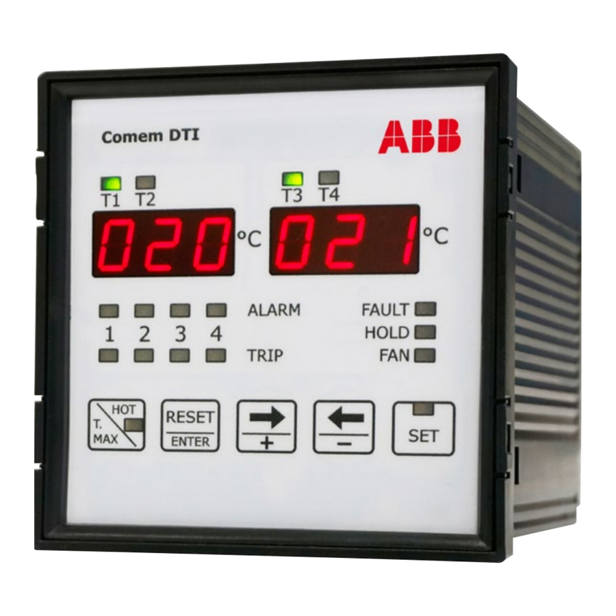
TEMPERATURE MONITORING DEVICE COMEM DTI AND COMEM EDTI - INSTRUCTION MANUAL — 5. Front panel description Legend: 1. LEDs T1-T2-T3-T4 for the on-measuring channel displayed 2. T1-T2 and T3-T4 displays for the channel temperature visualization and settings 3. LEDs ALARM for the Alarm status in the related channels (1 to 4) 4. -
Page 11: Programming Of The Device
TRANSFORMER COMPONENTS — 6. Programming of the device When the device is switched on, on the display will flash the index of the internal software: later the device starts to display the temperature read on the measured input. To enter in the programming mode, press the button SET for some second up to light the relative SET LED. -
Page 12: Selection Of The Number Of Active Inputs
TEMPERATURE MONITORING DEVICE COMEM DTI AND COMEM EDTI - INSTRUCTION MANUAL — 6. Programming of the device 6.2 Selection of the number of active inputs It is possible to select the number of activated inputs. It’s possible to choose between 3 and 4 inputs enabled; if there are 3 inputs enabled the T4 display remain off. -
Page 13: Selection Of The Threshold Of Switch On And Switch Off Ventilation
TRANSFORMER COMPONENTS 6.4 Selection of the threshold of switch-on and switch-off ventilation It is possible to program the threshold for enabling and disabling the ventilation. • Selection the threshold for disabling ventilation The FAN LED is on, with fixed light indicates this phase of programming. -
Page 14: Selection Of Address Network Identification For The Communication Of The Serial Port (Modbus-Rtu Protocol)
TEMPERATURE MONITORING DEVICE COMEM DTI AND COMEM EDTI - INSTRUCTION MANUAL — 6. Programming of the device 6.6 Selection of address network identification for the communication of the serial port (MODBUS-RTU protocol) NOTE THIS SETTING IS SIGNIFICANT ONLY FOR COMEM EDTI MODEL. -
Page 15: Selection Data Bit And Stop Bit
TRANSFORMER COMPONENTS 6.8 Selection data bit and stop bit NOTE THIS SETTING IS SIGNIFICANT ONLY FOR COMEM EDTI MODEL. This setting is indicated on displays with: • the type of parity on T1-T2 display • the number of data bit and stop bit on T3-T4 display. With ⇐... -
Page 16: Selection Of The Linked Channel With The Analogue Output
TEMPERATURE MONITORING DEVICE COMEM DTI AND COMEM EDTI - INSTRUCTION MANUAL — 6. Programming of the device 6.9 Selection of the linked channel with the analogue output NOTE THIS SETTING IS SIGNIFICANT ONLY FOR COMEM EDTI MODEL. This setting is indicated on displays with: •... -
Page 17: Configuration Output Signal
TRANSFORMER COMPONENTS 6.10 Configuration output signal NOTE NOTE THIS SETTING IS SIGNIFICANT ONLY FOR THE MAXIMUM LOAD FOR ANALOGUE COMEM EDTI MODEL. OUTPUT IS 400 Ω. In this phase it’s possible to define the type of signal of analogue output as 0-20 mA or 4-20 mA. This setting is indicated on displays with: •... -
Page 18: Configuration Diagnostic Probes
TEMPERATURE MONITORING DEVICE COMEM DTI AND COMEM EDTI - INSTRUCTION MANUAL — 6. Programming of the device 6.11 Configuration diagnostic probes This function allows to enable or to disable the control on the probes. This functionality controls the variation of the temperature in a defined time. -
Page 19: Modality Of Tripping And Restore
TRANSFORMER COMPONENTS — 7. Modality of tripping and restore 7.1 Alarm On the relative channel, if the threshold value set is exceeded of +1°C, after 5 seconds the ALARM relay is energized and the ALARM led is. The alarm rearm (relay de-energized and the involved LED off) occurs when the temperature goes down of 2°C respect at the threshold value set. -
Page 20: Diagnostic
TEMPERATURE MONITORING DEVICE COMEM DTI AND COMEM EDTI - INSTRUCTION MANUAL — 8. Diagnostic The device is provided of the thermic probes diagnostic function. The condition controlled on the measured input are: • Probe PT100 interrupted: signalling on the display the message O P E (open). -
Page 21: Visualization Of The Maximum Measured Temperature
TRANSFORMER COMPONENTS — 9. Visualization of the maximum measured temperature On the relative channel, if the threshold value set is exceeded of +1°C, after 5 seconds the ALARM relay is energized and the ALARM led is. The alarm rearm (relay de-energized and the involved LED off) occurs when the temperature goes down of 2°C respect at the threshold value set. -
Page 22: Visualization Of The Channels With The Higher Temperature
TEMPERATURE MONITORING DEVICE COMEM DTI AND COMEM EDTI - INSTRUCTION MANUAL — 10. Visualization of the channels with the higher temperature Pressing the HOT key for some seconds till switching to the HOT led. On the T1-T2 display, the hotter temperature among the inputs 1 and 2 will appear. -
Page 23: Technical Features
5 seconds – 2°C Measured visualization 2 displays with led 7 segments, 3-digits Outputs Comem DTI: 4 relay NO-C-NC (250 V 5 A resistive load) Comem eDTI: 4 relay NO-C-NC (250 V 5 A resistive load), 0-20 mA or 4-20 mA (Default); Modbus RTU... -
Page 24: Dimensions
TEMPERATURE MONITORING DEVICE COMEM DTI AND COMEM EDTI - INSTRUCTION MANUAL — 14. Dimensions... -
Page 25: Movement, Transport And Storage
The Comem DTI/eDTI temperature monitoring devices are shipped inside a cardboard box to facilitate transport and storage. As soon as the temperature monitoring device Comem DTI is received, the customer must perform the following operations: • examine the outer packaging surface to be sure that it is intact •... -
Page 26: Appendix A: Modbus Address
TEMPERATURE MONITORING DEVICE COMEM DTI AND COMEM EDTI - INSTRUCTION MANUAL — Appendix A: MODBUS Address Register Operations Description Notes address Operation for monitoring 0x280 CH1 Instantaneous Temperature [°C] 0x281 CH2 Instantaneous Temperature [°C] 0x282 CH3 Instantaneous Temperature [°C] 0x283 CH4 Instantaneous Temperature [°C]... - Page 27 TRANSFORMER COMPONENTS Register Operations Description Notes address Operation for controlling 0x300 R / W CH1 Alarm Setting [°C] 0x301 R / W CH2 Alarm Setting [°C] 0x302 R / W CH3 Alarm Setting [°C] 0x303 R / W CH4 Alarm Setting [°C] 0x310 R / W...
- Page 28 TEMPERATURE MONITORING DEVICE COMEM DTI AND COMEM EDTI - INSTRUCTION MANUAL — ABB S.p.A. COMEM Operating Unit Strada Regionale 11, Signolo 22 36054 Montebello Vicentino (VI) - ITALY www.abb.com/transformercomponents The data and illustrations are not binding. We reserve the right to modify the contents of this document without prior notice following technical and product developments.