ABB C1900 Series Installation Manual
Circular chart recorder and recorder/controller
Hide thumbs
Also See for C1900 Series:
- Operating manual (44 pages) ,
- Installation manual (28 pages) ,
- User manual (20 pages)
Table of Contents
Advertisement
Quick Links
—
A B B M E A S U R E M E N T & A N A LY T I C S | I N S TA L L AT I O N G U I D E | I M/C 1 9 0 0 - I N S R E V. Q
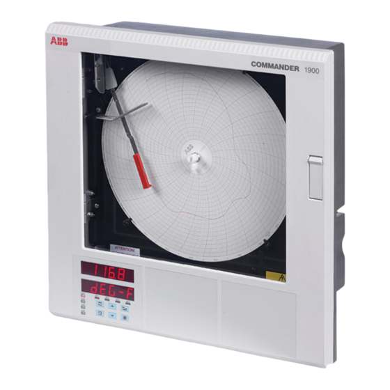
C1900
Circular chart recorder and recorder/controller
For more information
—
C1900
Further publications are available for free download
circular chart recorder
from:
and recorder/controller
www.abb.com/recorders
or by scanning this code:
Data Sheet
C1900
Circular chart recorder
Data Sheet
C1900
Circular chart recorder/controller
Quick Reference Guide
C1900 recorders
Quick Reference Guide
C1900 recorder and recorder/controller
Measurement made easy
Search for or click on
Operating Guide
DS/C1900R-EN
C1900
Circular chart recorders
Programming Guide
DS/C1900RC-EN
C1900
Circular chart recorders
Operating Guide
IM/C1900-QR
C1900
Circular chart recorder/controllers
Programming Guide
IM/C1900-QC
C1900
Circular chart recorder/controllers
Search for or click on
IM/C1900-OGR
IM/C1900-PGR
IM/C1900-OGC
IM/C1900-PGC
Advertisement
Table of Contents

Related Manuals for ABB C1900 Series


Summary of Contents for ABB C1900 Series
- Page 1 For more information — C1900 Further publications are available for free download circular chart recorder from: and recorder/controller www.abb.com/recorders or by scanning this code: Search for or click on Search for or click on Data Sheet Operating Guide C1900 DS/C1900R-EN...
- Page 2 Electrical safety Health and safety This equipment complies with the requirements of CEI/IEC To ensure that our products are safe and without risk to health, 61010-1:2001-2 ‘Safety Requirements for Electrical Equipment the following points must be noted: for Measurement, Control and Laboratory Use’. If the •...
-
Page 3: Table Of Contents
CONTENTS 1 INTRODUCTION Section Page The documentation for the C1900 series of circular chart recorders is shown in Fig. 1.1. The , including Standard Manuals the data sheet, are supplied with all instruments. The INTRODUCTION ............1 supplied depend on the specification of Supplementary Manuals the instrument. -
Page 4: Preparation
2 PREPARATION 2.1 Accessories – Fig. 2.1 2.2 Checking the Code Number – Fig. 2.2 2.2.1 Non-upgradeable Version Note. The 1901J is a basic, non-upgradeable single pen recorder. This version is not fitted with an analog output, relay, transmitter power supply unit or digital inputs and no additional modules can be fitted. -
Page 5: Mechanical Installation
3 MECHANICAL INSTALLATION 3.1 Siting – Figs 3.1 and 3.2 3.2 Mounting – Figs. 3.3 to 3.5 Dimensions in inches (mm) Minimum Sensor 15.04 (382) A – Close to Sensor 15.23 (386.8) B – At Eye-level Location C – Avoid Vibration 1.30 (33) Fig. -
Page 6: Wall-/Pipe-Mounting
…3 MECHANICAL INSTALLATION 3.2.1 Wall-/Pipe-Mounting – Fig. 3.4 Mark fixing centers on wall (4) . 8 1 ( 3 7 6 . 3 . 0 6 ( 2 8 1 . 0 Drill suitable holes (4) Secure mounting brackets (4) to case Secure instrument to wall using suitable fixings A –... -
Page 7: Panel Mounting
3 MECHANICAL INSTALLATION 3.2.2 Panel Mounting – Fig. 3.5 Dimensions in inches (mm) Drill four suitable holes 4 holes 0.281 dia. or tap for thread Mark four mounting holes 14.00 (355.6) 12.72 (323.08) minimum 14.19 11.25 (360.4) 12.72 (285.8) (323.1) minimum 1.70 (43.2) -
Page 8: Electrical Installation
4 ELECTRICAL INSTALLATION Warnings. • To comply with Underwriter Laboratories (UL) and Canadian Standards Association (CSA) certification, route signal leads and power cables in earthed (grounded), flexible metal conduit. Use the Position 1 protective ground stud (NOT the terminal module ground stud) to ground the flexible metal conduit. •... -
Page 9: Identifying The Input/Output Modules
4 ELECTRICAL INSTALLATION… 4.1 Identifying the Input/Output Modules – Fig. 4.2 To gain access to the modules, open the door and chassis – see Fig. 2.2. There are six module positions as shown in Fig. 4.2. 4.2 Channel Connections are made directly to the terminal block Channel 1 connections mounted on the motherboard. -
Page 10: Selecting The Analog Input Type(S)
…4 ELECTRICAL INSTALLATION 4.2.1 Selecting the Analog Input Type(s) – Figs. 4.3 and 4.4 Plug-in links are used to select the input type: PL1 & PL8 on the main p.c.b. (Fig. 4.3) Channel 1 PL1 & PL3 on the module (Fig. 4.4) Channels 2 to 4 DJ4 IC19 C 119... -
Page 11: Voltage And Current
4 ELECTRICAL INSTALLATION… 4.2.2 Voltage and Current – Fig. 4.5 4.2.5 Resistance Thermometer (RTD) – Fig. 4.5 Input impedances: If long leads are necessary it is preferable to use a 3-lead Low voltage (mV) >10MΩ resistance thermometer. Voltage >10MΩ If 2-lead resistance thermometers are used each input must be Current (mA) 100Ω... -
Page 12: Motorized Valve
…4 ELECTRICAL INSTALLATION 4.2.9 Motorized Valve – Fig. 4.6 A motorized valve with or without feedback requires 2 relays (common and normally open terminals) to drive the valve in either direction. Any two relays can be allocated for this function. Fig. 4.6 A shows two possible combinations. Note. -
Page 13: Module Connections
4 ELECTRICAL INSTALLATION… 4.3 Module Connections 4.3.3 Eight Digital Inputs or Outputs (Module Types 4 and 5 respectively) – 4.3.1 Standard I/O or Analog + Relay Figs. 4.8 and 4.9 (Module Types 1, 2 and 7) – Fig. 4.5 A plug-in link is used to select the board's function; digital inputs The connections are the same as Channel connections to the or digital outputs –... - Page 14 …4 ELECTRICAL INSTALLATION 4.4 Power Supply Connections – Fig. 4.10 Note. Recorders manufactured before June 2005 are fitted with a Mainboard that is not equipped with a universal power supply. Ensure the supply voltage selector switch is set correctly and the appropriate fuse is fitted –...
-
Page 15: Power Supply Connections
5 INSTALLATION RECORD... - Page 16 …5 INSTALLATION RECORD...
- Page 17 NOTES...
- Page 18 …NOTES...
- Page 19 Sales Service Software...
- Page 20 We reserve the right to make technical changes or modify the contents of this document without prior notice. With regard to purchase orders, the agreed particulars shall prevail. ABB does not accept any responsibility whatsoever for potential errors or possible lack of information in this document.