Table of Contents
Advertisement
Quick Links
Advertisement
Chapters
Table of Contents

Related Manuals for Maeda MC405C-3


Summary of Contents for Maeda MC405C-3
- Page 1 104ME-OM1901-00 Operation Manual Mini-Crawler Crane...
- Page 2 Improper use of this machine can lead to serious injury. The operators and maintenance personnel must carefully read this manual and sufficiently understand its contents before operation / inspecting / maintaining the machine. Keep this manual at hand to read it over anytime.
-
Page 3: Table Of Contents
Fly-Jib Dimensonal Drawing ................... 3-11 Outrigger Width Dimensional Drawing ..............3-12 RATED TOTAL LOAD CHARTS ..................3-13 Programmable Moment Limiter ................3-13 Reading the Angle Indicator ................3-13 Boom Length ......................3-14 Rated Total Load Chart for Standard Specification ..........3-16 1/2019 MC405C-3... - Page 4 Checking Before Operation ..................4-18 Visible Checks ....................4-18 Checking Before Starting Engine ............... 4-18 Checking After Starting Engine ................4-18 Normal Engine Start ....................4-18 Starting Engine in Cold Weather ................4-19 OPERATIONS AND CHECKS AFTER STARTING ENGINE .......... 4-20 1/2019 MC405C-3...
- Page 5 OUTRIGGER DISPLAY ....................4-38 OUTRIGGER UN-SET WARNING LAMP (YELLOW) ............4-39 OUTRIGGER OPERATION PANEL ................. 4-40 Work Selector Switch (Travel, Outrigger, Crane) ..........4-40 Outrigger Grounding Switches ................4-41 Outrigger Extension Switch ................4-41 OUTRIGGER SETTING ....................4-42 1/2019 MC405C-3...
- Page 6 Rated Total Load Display Section ..............4-76 Working Radius Display Section ................ 4-77 Boom Length Display Section ................4-77 Lifting Height Display Section ................4-77 Boom Angle Display Section ................4-77 Over Winding LED (Red) ................... 4-77 Outrigger Extension LED (Blue) ................ 4-77 1/2019 MC405C-3...
- Page 7 Messages in the A Mode Screen ..............4-100 An Example for Setting in the A Mode ............. 4-103 Procedure in the Operation Mode ................ 4-104 Call Out Crane Mode ..................4-104 Call Out Outrigger Mode .................. 4-105 REMOTE CONTROL SYSTEM VERIFICATIONS ............4-106 1/2019 MC405C-3...
- Page 8 Operation and Checking After Power Connection ..........4-136 Machine Operation ....................4-137 Machine Stop and Checks After Stopping Machine ..........4-138 Disconnecting Power Supply Cable ..............4-138 SEARCHER HOOK SAFETY PRECAUTIONS .............. 4-139 Handling Precautions ................... 4-139 Operating Precautions ..................4-139 1/2019 MC405C-3...
- Page 9 Keep the Machine Clean ..................5-8 Handle Water and Oil at Adequate Temperature ............. 5-8 Check Drain Oil and Oil Filter ................... 5-8 Cautions for Lubrication .................... 5-8 Protect Oil from Impurities ..................5-8 Attach a Warning Tag ....................5-8 1/2019 MC405C-3...
- Page 10 Pre-Start and Post-Start Inspection Items .............. 5-21 Pre-Start Visible Checks ..................5-22 Crane ......................... 5-23 Wire Ropes ......................5-23 Hook Block ......................5-23 Outriggers ......................5-23 Tracks and Frame ....................5-24 Engine ........................ 5-24 Travel and Crane Controls ................. 5-24 viii 1/2019 MC405C-3...
- Page 11 Inspect / Adjust Inlet Valve and Exhaust Valve Clearance ........ 5-55 Inspect / Clean / Test Fuel Injector ..............5-55 Check Crankcase Breather ................5-55 Check / Replace Engine Coolant ............... 5-55 Inspect / Clean EGR Valve ................5-56 1/2019 MC405C-3...
- Page 12 Inspection and Maintenance List ................5-81 Pre-Start and Post-Start Inspection Items ............5-81 Pre-Start – Before Starting Engine ................. 5-82 E-Boom, Frame and Hook ................. 5-82 Greasing ......................5-82 Searcher Hook Fix Bolts ..................5-82 Position Pin and Lynch Pin ................5-82 1/2019 MC405C-3...
- Page 13 Greasing Machine Units ..................5-87 TROUBLESHOOTING ..................... 5-88 General ........................5-88 Machine Body ......................5-88 Engine ........................5-88 Electrical Components .................... 5-89 Remote Control ....................... 5-90 Moment Limiter Error Causes and Actions to Be Taken ........5-93 Electric Motor ......................5-94 1/2019 MC405C-3...
- Page 14 Table of Contents Mini-Crawler Crane M A E D A This Page Intentionally Left Blank 1/2019 MC405C-3...
-
Page 15: Introduction
Section 1 INTRODUCTION 1/2019 MC405C-3... - Page 16 Machine maintenance procedures may be recording, taping, or information storage and updated by Maeda at any time. Always obtain the retrieval systems - without the written permission latest information from Maeda or a Maeda sales of Maeda Seisakusho Co., Ltd.
- Page 17 Section 2 SAFETY 1/2019 MC405C-3...
-
Page 18: Safety Definitions
Section 2 – SAFETY DEFINITIONS Mini-Crawler Crane M A E D A SAFETY DEFINITIONS SAFETY PRECAUTIONS Maeda is concerned for your safety and the There is no substitute for common sense and condition of your mini-crawler crane. Safety careful practices. Improper practices or... - Page 19 Look at the level gauge when making adjustments during operation. Always keep the machine body level when operating. ・Sudden or jerky movement of the travel, crane or outrigger controls can cause the machine to tip over. Always operate these controls smoothly. 1/2019 MC405C-3...
- Page 20 ・Never hoist more than one load at a time. cool. ・When you hoist a long load, such as pipes, clamp the load vertically or secure it at both ends. 1/2019 MC405C-3...
- Page 21 ・Always read and follow safety-related shoes, and eye and hearing precautions found on containers of hazardous protection, as required by substances like parts cleaners, primers, the task at hand. sealants and sealant removers. ・Undersized wiring systems can cause an electrical fire. 1/2019 MC405C-3...
- Page 22 ・Always stop the engine before with your hands. Always use a piece of wood beginning service. or cardboard. Have your authorised Maeda dealer or distributor repair the damage. ・If the engine must be serviced while it is Flying Object Hazard...
- Page 23 Working Above Machine Hazard ・Always maintain three-point contact as you climb on or off an elevated work surface. ・Do not jump from the elevated work surface. ・Do not climb on the boom, outrigger or other machine surface. 1/2019 MC405C-3...
- Page 24 Retrieve any tools or parts that may have dropped inside of the machine to avoid improper machine operation. Never dispose of hazardous materials by dumping them into a sewer, on the ground, or into groundwater or waterways. 1/2019 MC405C-3...
-
Page 25: Safety Label Locations
Mini-Crawler Crane M A E D A Section 2 – SAFETY LABEL LOCATIONS SAFETY LABEL LOCATIONS Machine Body Fig. 2-1 1/2019 MC405C-3... - Page 26 Section 2 – SAFETY LABEL LOCATIONS Mini-Crawler Crane M A E D A Fig. 2-2 2-10 1/2019 MC405C-3...
- Page 27 Mini-Crawler Crane M A E D A Section 2 – SAFETY LABEL LOCATIONS [3] 104-3279801 1/2019 MC405C-3 2-11...
- Page 28 Section 2 – SAFETY LABEL LOCATIONS Mini-Crawler Crane M A E D A [4-A] 104-3433200 [4-B] 104-3433300 [4-C] 104-3433400 2-12 1/2019 MC405C-3...
- Page 29 Mini-Crawler Crane M A E D A Section 2 – SAFETY LABEL LOCATIONS [11] 104-4760600 [8] 349-3195100 [12] 104-4548600 [9] 349-4420700 [10] 104-4753500 (2 places) [13] 349-4421100 1/2019 MC405C-3 2-13...
- Page 30 Section 2 – SAFETY LABEL LOCATIONS Mini-Crawler Crane M A E D A [14-A] 104-2209900 2-14 1/2019 MC405C-3...
- Page 31 Mini-Crawler Crane M A E D A Section 2 – SAFETY LABEL LOCATIONS [14-B] 104-2210200 1/2019 MC405C-3 2-15...
- Page 32 Section 2 – SAFETY LABEL LOCATIONS Mini-Crawler Crane M A E D A [14-C] 104-2210300 2-16 1/2019 MC405C-3...
- Page 33 Mini-Crawler Crane M A E D A Section 2 – SAFETY LABEL LOCATIONS [21] 349-4421400 [30] 104-4550800 [26] 350-4539700 (4 places) [45] 349-4426900 (4 places) 1/2019 MC405C-3 2-17...
- Page 34 Section 2 – SAFETY LABEL LOCATIONS Mini-Crawler Crane M A E D A [51] 349-4527000 [46] 349-4427000 (4 places) [54] 349-4421900 [56] 893-4239100 [47] 349-4427100 [50] 349-4427200 2-18 1/2019 MC405C-3...
- Page 35 Mini-Crawler Crane M A E D A Section 2 – SAFETY LABEL LOCATIONS [57] 349-4427300 [58] 349-4427400 [61] 349-4526900 [59] 349-4427500 [63] 349-4427800 [60] 349-4427900 [70] 104-4549200 (4 places) 1/2019 MC405C-3 2-19...
- Page 36 Section 2 – SAFETY LABEL LOCATIONS Mini-Crawler Crane M A E D A [76] 553-4267500 (2 places) [73] 349-4422000 [77] 553-4267400 (2 places) [75] 553-4268000 (2 places) [78] 553-4266400 2-20 1/2019 MC405C-3...
- Page 37 Mini-Crawler Crane M A E D A Section 2 – SAFETY LABEL LOCATIONS [80] 104-3393000 [85] 353-4488600 [81] 104-3287200 [83] 104-4752900 [87] 104-4549601 (4 places) [84] 349-4536600 1/2019 MC405C-3 2-21...
- Page 38 Section 2 – SAFETY LABEL LOCATIONS Mini-Crawler Crane M A E D A [92] 553-4267100 [95] 104-4557900 (2 places) [89] 104-4569800 [96] 104-3327800 2-22 1/2019 MC405C-3...
- Page 39 Mini-Crawler Crane M A E D A Section 2 – SAFETY LABEL LOCATIONS [106] 103-4604800 [97] 350-4432100 [98] 104-4558200 (2 places) [107] 103-4604900 [108] 553-4267700 1/2019 MC405C-3 2-23...
-
Page 40: Remote Control System
Section 2 – SAFETY LABEL LOCATIONS Mini-Crawler Crane M A E D A Remote Control System Transmitter Receiver Fig. 2-3 2-24 1/2019 MC405C-3... - Page 41 Mini-Crawler Crane M A E D A Section 2 – SAFETY LABEL LOCATIONS [1] 349-4428500 [68] 300-4214000 [99] 104-4559400 [23] 104-4559300 1/2019 MC405C-3 2-25...
-
Page 42: Electric Motor (Option)
Section 2 – SAFETY LABEL LOCATIONS Mini-Crawler Crane M A E D A Electric Motor (Option) Fig. 2-4 [70] 104-4552400 (4 places) [102] 553-4267300 (2 places) 2-26 1/2019 MC405C-3... -
Page 43: 850Kg Searcher Hook (Option)
Mini-Crawler Crane M A E D A Section 2 – SAFETY LABEL LOCATIONS 850kg Searcher Hook (Option) Fig. 2-5 1/2019 MC405C-3 2-27... - Page 44 Section 2 – SAFETY LABEL LOCATIONS Mini-Crawler Crane M A E D A [4] 102-4621200 (2 places) [1] 102-4608500 (2 places) [2] 103-4635800 [3] 103-4635500 2-28 1/2019 MC405C-3...
- Page 45 Mini-Crawler Crane M A E D A Section 2 – SAFETY LABEL LOCATIONS [S1] 104-1165400 1/2019 MC405C-3 2-29...
-
Page 46: Fly-Jib (Option)
Section 2 – SAFETY LABEL LOCATIONS Mini-Crawler Crane M A E D A Fly-Jib (Option) Fig. 2-6 2-30 1/2019 MC405C-3... - Page 47 Mini-Crawler Crane M A E D A Section 2 – SAFETY LABEL LOCATIONS [2] 104-4568200 (2 places) [6] 104-4572800 (2 places) [3] 104-4568300 (2 places) [4] 104-3300300 [7] 104-4579800 [5] 104-4572700 (2 places) [F1] 104-3300200 1/2019 MC405C-3 2-31...
- Page 48 Section 2 – SAFETY LABEL LOCATIONS Mini-Crawler Crane M A E D A This Page Intentionally Left Blank 2-32 1/2019 MC405C-3...
-
Page 49: Specifications, Terminology And Capacity Charts
Section 3 SPECIFICATIONS, TERMINOLOGY AND CAPACITY CHARTS 1/2019 MC405C-3... -
Page 50: Machine Features
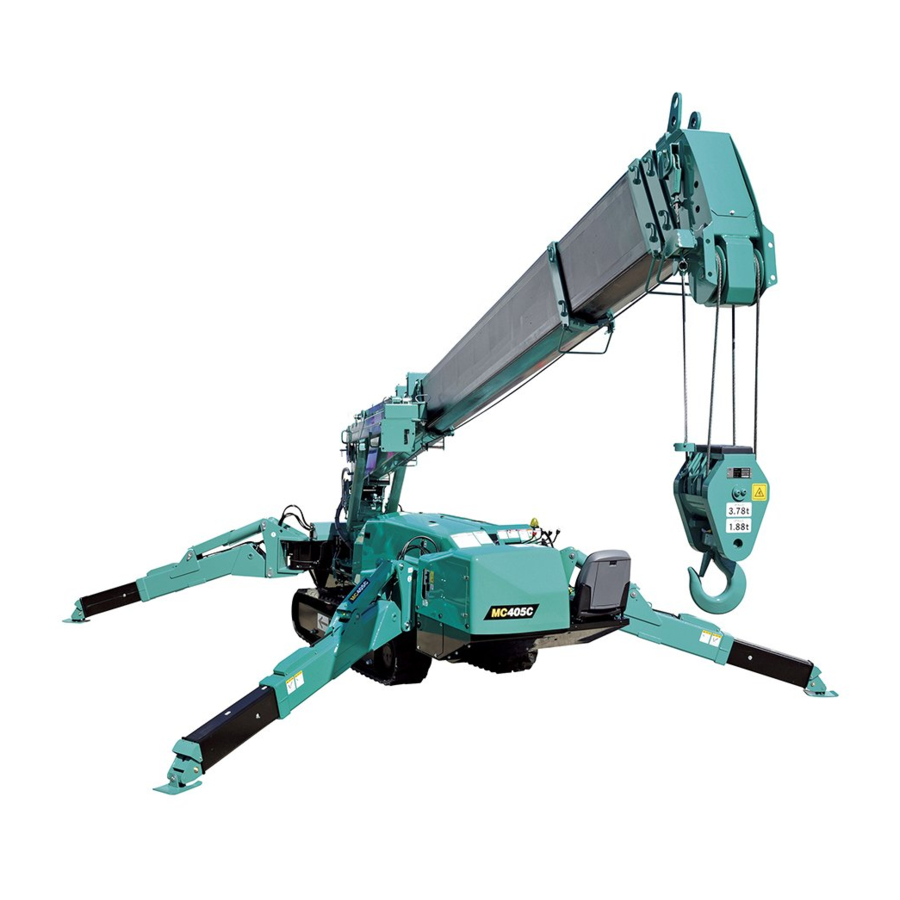
A remote control system allows remote crane operation. 1/2019 MC405C-3... -
Page 51: Crane Terminology
Fig. 3-5 Working Radius A horizontal distance between the axis of slewing and the hook centre. Fig. 3-2 Boom Length A distance between the boom primary pin and the sheave pin of the end boom. Fig. 3-3 1/2019 MC405C-3... -
Page 52: Principle Specifications List
49.0kPa (0.50kgf/cm Double-throw variable piston Double-throw variable piston Hydraulic pump pump (17cc/rev 2) pump (13cc/rev × 2) Travelling: 20.6MPa (210kgf/cm Hydraulic system Crane high-pressure relief: 20.1MPa (205kgf/cm Rated pressure Crane low-pressure relief: 4.41 to 6.37MPa (45 to 65kgf/cm 1/2019 MC405C-3... - Page 53 15-degree inclination), travelling lever lock, travelling/crane/outrigger selector switch (designed to prevent the machine from craning at travelling), outrigger safety device (outrigger interlock and crane interlock), moment limiter (working envelope limited), working status lamp, outrigger un-set warning lamp Classification Mobile crane ISO4301/2 Group A1 1/2019 MC405C-3...
-
Page 54: Remote Control System Specifications
Slewing Counterclockwise (left) / clockwise (right) Power ON/OFF Horn Warning signal Hook stow/Setting Hook stowing/Mode setting Push button switches Speed/Mode Speed control/Mode selection Start/Reset Engine start/Reset Stop/EMO Engine stop/Emergency stop Trigger type accelerator Hydraulic control + Engine control 1/2019 MC405C-3... -
Page 55: 850 Kg Searcher Hook Specifications
System / Item Standard Electric motor option Machine mass 5630 kg 5780 kg Mass and dimensions Stowed 5210 × 1380 × 2060 mm length × width × height Crane capacity 850 kg Performance Maximum working radius 17.0 m 1/2019 MC405C-3... -
Page 56: Fly-Jib Specifications
Section 3 – PRINCIPLE SPECIFICATIONS LIST Mini-Crawler Crane M A E D A Fly-Jib Specifications MC405C-3 MC405C-3 System / Item Standard Electric motor option Mass and dimensions Machine mass 5750 kg 5900 kg Crane capacity Performance 520 kg 1/2019 MC405C-3... -
Page 57: Dimensional Drawings
Mini-Crawler Crane M A E D A Section 3 – DIMENSIONAL DRAWINGS DIMENSIONAL DRAWINGS Machine Dimensional Drawing Fig. 3-6 1/2019 MC405C-3... -
Page 58: 850 Kg Searcher Hook Dimensonal Drawing
Section 3 – DIMENSIONAL DRAWINGS Mini-Crawler Crane M A E D A 850 kg Searcher Hook Dimensonal Drawing Fig. 3-7 3-10 1/2019 MC405C-3... -
Page 59: Fly-Jib Dimensonal Drawing
Mini-Crawler Crane M A E D A Section 3 – DIMENSIONAL DRAWINGS Fly-Jib Dimensonal Drawing Fig. 3-8 1/2019 MC405C-3 3-11... -
Page 60: Outrigger Width Dimensional Drawing
Section 3 – DIMENSIONAL DRAWINGS Mini-Crawler Crane M A E D A Outrigger Width Dimensional Drawing Fig. 3-9 3-12 1/2019 MC405C-3... -
Page 61: Rated Total Load Charts
1.63 t if booms (1) + (2). 1.13 t if booms (1) + (2) + (3). 0.83 t if booms (1) + (2) + (3) + (4). 0.44 t if booms (1) + (2) + (3) + (4) + (5). 1/2019 MC405C-3 3-13... -
Page 62: Boom Length
"Boom (1) + (2) + (3)": With booms (4) and (5) retracted, booms (2) and (3) are fully extended. "Boom (1) + (2) + (3)" is to apply to crane operation with boom (3) extended even if only slightly. Fig. 3-13 3-14 1/2019 MC405C-3... - Page 63 "Boom (1) + (2) + (3) + (4) + (5)": All the booms are fully extended. "Boom (1) + (2) + (3) + (4) + (5)" is to apply to crane operation with half of the " mark" on boom (4) passes boom (3). Fig. 3-15 1/2019 MC405C-3 3-15...
-
Page 64: Rated Total Load Chart For Standard Specification
Standard wire rope specification: 6xWs (26) Deductions from rated total loads must be IWRC, 8 mm diameter, 92 m made for the weight of hook block, ball/hook, Specified breaking load: 42.4 kN slings, rigging or other suspended gear. 3-16 1/2019 MC405C-3... -
Page 65: Rated Total Load Chart - 4 Falls
2580 5.00 1680 5.00 1630 6.00 5.00 1680 6.00 1180 6.00 1180 7.00 6.00 1180 7.00 7.00 8.00 7.00 8.00 8.00 9.00 7.25 9.00 9.00 10.00 10.20 10.00 11.00 11.00 12.00 12.00 13.00 13.10 14.00 15.00 16.00 1/2019 MC405C-3 3-17... -
Page 66: Rated Total Load Chart - 2 Falls
1930 5.00 1680 5.00 1630 6.00 5.00 1680 6.00 1180 6.00 1180 7.00 6.00 1180 7.00 7.00 8.00 7.00 8.00 8.00 9.00 7.25 9.00 9.00 10.00 10.20 10.00 11.00 11.00 12.00 12.00 13.00 13.10 14.00 15.00 16.00 3-18 1/2019 MC405C-3... -
Page 67: Rated Total Load Chart - Single Fall
4.00 5.00 3.50 4.00 4.50 5.50 4.00 5.00 5.00 6.00 5.00 6.00 6.00 7.00 6.00 7.00 7.00 8.00 7.00 8.00 8.00 9.00 7.25 9.00 9.00 10.00 10.20 10.00 11.00 11.00 12.00 12.00 13.00 13.10 14.00 15.00 16.00 1/2019 MC405C-3 3-19... -
Page 68: Rated Total Load Chart For 850 Kg Searcher Hook
If boom (4) is extended to any extent, work should be performed within the capacity for "13.565m Boom". When more than one half of the third mark is exposed from the boom (3), work should be carried out within the performance for the "16.475m Boom". 3-20 1/2019 MC405C-3... - Page 69 Mini-Crawler Crane M A E D A Section 3 – RATED TOTAL LOAD CHARTS OFFSET POSITION SH1 Fig. 3-16 OFFSET POSITION SH2 Fig. 3-17 OFFSET POSITION SH3 Fig. 3-18 1/2019 MC405C-3 3-21...
-
Page 70: Rated Total Load Chart For Fly-Jib
Rated Total Load Chart for Fly-Jib CAUTION: The rated total load is a load including the mass of a hoisting accessory (hook: 20kg). Rated total load chart Boom angle (deg) Rated total load (kg) 72 and over 3-22 1/2019 MC405C-3... -
Page 71: Working Radius/Lifting Height
• The boom (4) in the diagram of working radius and lifting height represents a state that half of the " mark" passes boom (3). Fig. 3-19 1/2019 MC405C-3 3-23... - Page 72 This is load radius. The rated total load decreases with increase in the working radius. Actual crane operation requires the planning of work, allowing for sufficient clearance more than that provided in the diagram. Fig. 3-20 Fig. 3-21 3-24 1/2019 MC405C-3...
-
Page 73: During Pick & Carry
2. Do not slew. Avoid any sharp movements when stopping or starting. 3. When travelling with a load, keep it low to the ground as possible. 4. If the load slews, stop travelling until the load is still. Fig. 3-22 1/2019 MC405C-3 3-25... -
Page 74: Working Radius/Lifting Height For 850 Kg Searcher Hook
• Number of falls mode and searcher hook offset position must be set as “850 kg searcher hook mode” when 850 kg searcher hook is used. Searcher hook offset position must be displayed on moment limiter boom length window. • Never use the searcher hook and the crane hook simultaneously. Fig. 3-23 3-26 1/2019 MC405C-3... - Page 75 Mini-Crawler Crane M A E D A Section 3 – WORKING RADIUS/LIFTING HEIGHT Fig. 3-24 Fig. 3-25 1/2019 MC405C-3 3-27...
-
Page 76: Working Radius/Lifting Height For Fly-Jib
WARNING! The diagram of working radius and lifting height shows the relationships the working radius of this machine, boom angle, and lifting height above the ground with no object hoisted. The diagram has been made allowing for no deflection in the boom. Fig. 3-26 3-28 1/2019 MC405C-3... - Page 77 Section 4 OPERATION 1/2019 MC405C-3...
-
Page 78: Machine Components
24 - Travelling motor and sprocket 10 - Outrigger 25 - Track roller 11 - Slewing device 26 - Idler 12 - Working status lamp 27 - Carrier roller 13 - Rubber track 28 - Working light 14 - Travel control 1/2019 MC405C-3... - Page 79 Track Roller, Idler, Carrier Roller Travel device for travelling. Travel Control A part for travel control of the machine. For operation method of travelling, see “TRAVELLING CONTROLS AND OPERATION” on page 4-23. Crane Control A part for controlling the crane. 1/2019 MC405C-3...
-
Page 80: Travel And Crane Controls
10 - Left travelling lever 4 - Boom derricking lever 11 - Moment limiter display panel 5 - Outrigger un-set warning lamp 12 - Instrument panel 6 - Acceleration pedal 13 - Outrigger operation panel 7 - Level 1/2019 MC405C-3... -
Page 81: Acceleration Pedal
Fig. 4-7 • Lower: Push the lever forward (Lower). • Neutral: Release your hand from the lever. The lever returns to the "Neutral" position and the boom derricking stops. • Raise: Pull the lever toward you (Raise). Fig. 4-5 1/2019 MC405C-3... -
Page 82: Travelling Lock Lever
• Spin turn: Operate the left and right levers to the opposite direction. The left and right crawlers turn to the opposite direction, allowing you to make the spin turn. 1/2019 MC405C-3... -
Page 83: Instrument Panel Sections
13 - Engine water temperature monitor 6 - Horn switch 14 - Engine oil pressure monitor 7 - Engine emergency stop switch (EMO) 15 - Battery charge monitor 8 - Starter switch 16 - Boom lift bypass switch 1/2019 MC405C-3... -
Page 84: Switches
"OFF" and the crane operating speed returns to normal. NOTICE: Always set the work selector switch on the outrigger operation panel to the "Crane" position. If the work selector switch is at other position than "Crane", the crane high-speed switch does not work. 1/2019 MC405C-3... - Page 85 "ON" position and • ON: Press the switch. The engine stops. extinguishes at the "OFF" position. • OFF: Turn the switch clockwise (direction of the arrow in the figure). The switch returns to the original position. 1/2019 MC405C-3...
- Page 86 • ON: Push down the switch to the left. The machine is now in the Pick & Carry posture mode. • OFF: Push down the switch to the right. The Pick & Carry posture mode is cancelled. 4-10 1/2019 MC405C-3...
-
Page 87: Monitors
If the engine is in operation, the meter indication advances even if the machine is not travelling. The meter indication advances for "1" when the machine has been running for 1 hour regardless of the engine rotation speed. Fig. 4-25 1/2019 MC405C-3 4-11... - Page 88 If it lights up during the operation, there is an core, and damage and tension of the alternator error in the battery charge system. belt. Immediately stop the machine and check the tension of the alternator belt. Fig. 4-27 Fig. 4-29 4-12 1/2019 MC405C-3...
-
Page 89: Operation Seat
Fig. 4-31 While pushing the slide adjusting lever (3) leftward, move the seat (2) forward/backward. After adjusting the seat (2), release your hand from the slide adjusting lever (3). The seat (2) is fixed to the position. 1/2019 MC405C-3 4-13... -
Page 90: Operation Related Precautions
• Make sure no person or object is within the boom slewing radius area before starting engine. • Blow the horn for warning before starting the engine. • Do not start the engine by short-circuiting the starter circuit. Such may cause a fire. 4-14 1/2019 MC405C-3... -
Page 91: After Starting Engine
• Fix the hook block to the containment position. • Make the outrigger contained. For more information, see "TRAVELLING POSITION" on page 4-23. • Make sure again that no one or object is in the vicinity before starting to move. 1/2019 MC405C-3 4-15... -
Page 92: Cold Weather Operation
• Remove snow and/or ice laid on the Machine that causes the safety nameplates to be hard to read. Be especially careful to securely remove those that are on the boom and thus may fall. Fig. 4-38 4-16 1/2019 MC405C-3... -
Page 93: Cautions Under Cold Weather
①, switches, sensors or similar part. If the infiltrated condensation and/or similar substance freezes, the Machine may operate improperly upon the next use and cause unexpected accidents. Fig. 4-40 1/2019 MC405C-3 4-17... -
Page 94: Starting Engine
(open) before starting the engine. • Verify that the main switch on the reciver is at the "OFF" position. Lightly step on the acceleration pedal (6) to operate the engine at low speed. Fig. 4-42 4-18 1/2019 MC405C-3... -
Page 95: Starting Engine In Cold Weather
NOTICE: When the starter switch is operated to the "HEAT" (preheat) position, the "preheat monitor" lights up, indicating that the engine is preheated. When the engine preheating has completed, the "preheat monitor" goes off. Fig. 4-49 Fig. 4-46 1/2019 MC405C-3 4-19... -
Page 96: Operations And Checks After Starting Engine
• When the engine has started, check if the "battery charge monitor" and "engine oil pressure monitor" went off. If there is any abnormality, repair. • Do not leave the engine in low idling or high idling for more than 20 minutes. 4-20 1/2019 MC405C-3... - Page 97 Operate the boom telescoping lever (2) slowly forward / backward to extend/retract the boom until it reaches the stroke end. Check if there is any abnormality with the operation. Fig. 4-56 If there is any abnormality, repair. Fig. 4-54 1/2019 MC405C-3 4-21...
-
Page 98: Stopping Engine
(6) and change the engine speed to idling. Continue the no-load operation for about 5 minutes. Fig. 4-57 Turn the starter switch key to the "OFF" position. The engine will stop. Fig. 4-58 Remove the starter switch key. 4-22 1/2019 MC405C-3... -
Page 99: Travelling Position
49 to stow the outriggers. Allowable Water Depth Use this machine in the water of the depth of under the centre of the idler (1) where the muffler beneath the machine body doesn’t go under water. Fig. 4-61 1/2019 MC405C-3 4-23... -
Page 100: Cautions On Upward/Downward Slope
Operating the travelling lever to the "Neutral" position automatically brakes the machine, but may overrun when going down the slope at high speed. 4-24 1/2019 MC405C-3... -
Page 101: Starting Travelling Machine
• Operate the work selector switch to the "Travel" position and the travelling lock lever to the "Travel" position. Preparation Before Starting Travelling Operate the work selector switch on the outrigger operation panel to the "Travel" position. Fig. 4-67 Fig. 4-64 1/2019 MC405C-3 4-25... -
Page 102: Changing Machine Travelling Mode
Operate the left travelling lever. Tilt the left travelling lever forward to turn to the Fig. 4-68 right in the forward direction. Tilt the left travelling lever toward you to turn to the right in the backward direction. 4-26 1/2019 MC405C-3... -
Page 103: Spin Turns
While tilting the left travelling lever forward, return only the right travelling lever to the "Neutral" position. Right Turn While Travelling Backward While tilting the left travelling lever toward you, return only the right travelling lever to the "Neutral" position. Fig. 4-70 Fig. 4-71 1/2019 MC405C-3 4-27... -
Page 104: Stopping/Parking Machine
Bring the key with you when you leave the machine. Operate the left and right travelling levers to the "Neutral" position at the same time. This automatically brakes the machine and the machine stops. Fig. 4-73 4-28 1/2019 MC405C-3... -
Page 105: Description On Outrigger And Crane Safety Devices
Please contact us or our sales service agency. WARNING! Understand well the operation sequence below, warning display from the safety devices under the corresponding machine conditions, and the details of operation stop. Keep these in mind for safe operations. 1/2019 MC405C-3 4-29... -
Page 106: Check Before Setting Outriggers
OFF] • Check the level with the level. [Working status lamp (red) OFF] When the machine tilts for 3 • Warning buzzer sounds Crane inclination alarm device degrees or more during outrigger continuously is activated setting operation 4-30 1/2019 MC405C-3... -
Page 107: Crane Operations
• If the boom stowing lamp • Boom stowing lamp on display • Fully retract the boom (green) does not light up, all panel ON • Boom horizontal stowing position the outrigger operations • Boom slew and stow position stop. 1/2019 MC405C-3 4-31... -
Page 108: Outrigger Stowing Operation
• Travelling lock lever at "Travel" position • Start the engine. • Operate the travelling levers. When the machine tilts for 15 • Warning buzzer sounds Crane inclination alarm device degrees or more during travelling continuously is activated operation 4-32 1/2019 MC405C-3... -
Page 109: Description Of Pick & Carry Safety Devices
OFF] • Check the level with the level. [Working status lamp (red) OFF] When the machine tilts for 3 • Warning buzzer sounds Crane inclination alarm device is degrees or more during outrigger continuously activated setting operation 1/2019 MC405C-3 4-33... -
Page 110: Crane Operations
• Alarm buzzer sounds Over winding detector is activated When winching excessively continuously Winch winding operation stops When the machine tilts for 3 • Warning buzzer sounds Crane inclination alarm device is degrees or more during crane continuously activated operation 4-34 1/2019 MC405C-3... -
Page 111: Outrigger Setting Operation
[Working status lamp (red) ON] pin. • Stop the engine. When the machine tilts for 3 • Warning buzzer sounds Crane inclination alarm device is degrees or more during outrigger continuously activated stowing operation 1/2019 MC405C-3 4-35... -
Page 112: Machine Travelling Operation
• Travelling lock lever at "TRAVEL" position • Start the engine. • Operate the travelling levers. When the machine tilts for 15 • Warning buzzer sounds Crane inclination alarm device is degrees or more during travelling continuously activated operation 4-36 1/2019 MC405C-3... -
Page 113: Outrigger Components
Section 4 – OUTRIGGER COMPONENTS OUTRIGGER COMPONENTS Fig. 4-75 1 - Position pin 5 - Outer box 2 - Rotary 6 - Inner box 3 - Outrigger setting cylinder 7 - Outrigger adapter (Tray) 4 - Outrigger extension cylinder 1/2019 MC405C-3 4-37... -
Page 114: Outrigger Display
(1) at the tip of the detected by the detection switch (1) of the inner box (2) and by the detection switch inside outrigger rotary. the inner box. Fig. 4-78 Fig. 4-77 4-38 1/2019 MC405C-3... -
Page 115: Outrigger Un-Set Warning Lamp (Yellow)
Boom movements are detected by the projection Fig. 4-82 (4) (movable) at the side of the boom rear edge and the detection switch (3) (fixed) at the boom connection. Fig. 4-80 1/2019 MC405C-3 4-39... -
Page 116: Outrigger Operation Panel
• When operating the work selector switch to the "Travel" position, be sure to stow the crane and put the machine in the "travelling posture". Operating the machine not in the "travelling posture" can overturn the machine, resulting in serious accidents. 4-40 1/2019 MC405C-3... -
Page 117: Outrigger Grounding Switches
• Neutral: Release your finger from the switch. The switch returns to the "Neutral" position and the outrigger extension cylinder stops telescoping. • OUT: Push down the switch downward. The outrigger extension cylinder extends and you can extend the outrigger. 1/2019 MC405C-3 4-41... -
Page 118: Outrigger Setting
Setting the outriggers with the tilted ground Fig. 4-91 surface without levelling the ground surface will cause the outriggers to slip or overturn, causing serious accidents. 4-42 1/2019 MC405C-3... - Page 119 • Always place the machine in a horizontal position with the use of the level when extending the outriggers. A warning buzzer sounds when the machine is inclined 3° or more and stops when the machine is placed in a horizontal position. Fig. 4-94 1/2019 MC405C-3 4-43...
-
Page 120: Tasks To Be Performed Upon Engine Stop
Fig. 4-98 Crane operation should proceed with respect to the values specified in "When the crane is used with the outriggers extended Fig. 4-100 at the minimum" in the rated total load chart. 4-44 1/2019 MC405C-3... - Page 121 Fig. 4-103 Verify that the boom stowing lamp (1) (green) on the outrigger display is ON. Fig. 4-107 NOTICE: The boom stowing lamp (1) and four outrigger extension lamps (2) on the outrigger Fig. 4-104 display are ON. 1/2019 MC405C-3 4-45...
-
Page 122: Tasks To Be Performed After Starting Engine
Set the switch to the "Neutral" idling. position. Fig. 4-108 Fig. 4-111 Check the number on the operation plate at the switches on the outrigger operation panel to determine which outrigger to be operated. Fig. 4-112 Fig. 4-109 4-46 1/2019 MC405C-3... - Page 123 (6) and check if there is any Repeat this operation to gradually raise the machine until the rubber tracks will be at the foreign object pinched in the bending section. height of about 50 mm above the ground. Fig. 4-117 Fig. 4-114 1/2019 MC405C-3 4-47...
-
Page 124: Outrigger Extension Modes
NOTICE: If even a group of outriggers is Approx. 50mm is assured for clearance "a" retracted to a medium point, all the outriggers are (between the outrigger bottom and crawler deemed to be extended at the medium. bottom) in the figure. Fig. 4-119 4-48 1/2019 MC405C-3... -
Page 125: Outrigger Minimum Extension
• Do not perform the outrigger extending operation after they are set on the ground. Doing so applies unreasonable force on the outriggers, resulting in the outrigger breakage. • Always set the travelling lock lever to the "LOCK" position when operating the outriggers. 1/2019 MC405C-3 4-49... -
Page 126: Tasks To Be Performed After Starting Engine
(outrigger [1] and [4]) or two rear switches (outrigger [2] and [3]). Operating two left or right switches at the same time will suddenly raise two outriggers on one side, causing overturning of the machine. 4-50 1/2019 MC405C-3... - Page 127 "IN" (upward) side. When the setting cylinder completely retracts and the top box goes up to the upper limit, release your finger from the outrigger grounding switch. Fig. 4-133 1/2019 MC405C-3 4-51...
-
Page 128: Tasks To Be Performed Upon Engine Stop
(2) on the outrigger display went off. Fig. 4-137 NOTICE: On the outrigger display, the boom stowing lamp (1) (green) is illuminated and four outrigger extension lamps (2) and four outrigger grounding lamps (3) are flashing in red. 4-52 1/2019 MC405C-3... -
Page 129: Working With Crane
Especially be careful for these Always set the outrigger horizontally to the operations. ground while looking at the level gauge. 1/2019 MC405C-3 4-53... - Page 130 (2) Evacuate the machine completely away boom/machine frame and electrical cables. from the cause of the charge, make sure the machine is not charged, rescue the electrically shocked personnel and immediately carry to the hospital. 4-54 1/2019 MC405C-3...
- Page 131 Be fully careful when working. • When an earthquake occurs, abort working and wait until the earthquake is over. 1/2019 MC405C-3 4-55...
- Page 132 When the view is bad because of bad weather (rain, fog, and snow), abort working and wait until the weather recovers. • Do not use for purpose, for instance raising a person using a crane, other than the true purpose. 4-56 1/2019 MC405C-3...
- Page 133 • Do not let the hook block hit the ground. • Before leaving the hook block lowered for a long time for instance when working with underground, leave at least three loops of wire rope in the winch drum. 1/2019 MC405C-3 4-57...
- Page 134 Be careful to prevent the boom from hitting outriggers during slewing operation. 4-58 1/2019 MC405C-3...
- Page 135 / automatic stop device as the safety device, but even then be fully careful to prevent this safety device from activating. • Make sure signs are communicated fully. • Be especially careful with the crane operations. 1/2019 MC405C-3 4-59...
-
Page 136: Crane Operation
Do Not Pull Sideward, Draw in, and Hoist Diagonally Pulling sideward, drawing in, or hoisting diagonally applies unreasonable force on the machine. It not only damages the machine body, but also is dangerous. Never operate in these ways. 4-60 1/2019 MC405C-3... - Page 137 Be careful not to hook the wire rope over a tree or steel beam while working. If it gets stuck with something, do not force to wind the wire. Untangle and then wind the wire. Fig. 4-154 1/2019 MC405C-3 4-61...
-
Page 138: Before Crane Operations
"ON" position. Fig. 4-159 Fig. 4-156 NOTICE: If the moment limiter override switch is set to the "ON" position, the working status lamp will flash in red, and the warning buzzer will sound. 4-62 1/2019 MC405C-3... -
Page 139: Crane Operation Posture
• Raise: Pull the lever to the "UP" side toward you. NOTICE: Adjust the winch raising/lowering speed Fig. 4-162 with the winch lever and stroke of the acceleration pedal. 1/2019 MC405C-3 4-63... -
Page 140: Boom Derricking Operation
• Do not pull the load horizontally or pull in the load by telescoping the boom. 4-64 1/2019 MC405C-3... -
Page 141: Slewing Operation
"LEFT" side. • Neutral: Release your hand from the lever. The lever returns to the "Neutral" position and the slewing stops. • Slew clockwise (right): Pull the lever toward you to the "RIGHT" side. 1/2019 MC405C-3 4-65... -
Page 142: Crane Stowing Operation
Operate the boom telescoping lever (2) to the "RETRACT" (pull toward you) side to fully retract the boom. Fig. 4-172 NOTICE: When the boom stowing switch is at the "ON" position, the pilot lamp at the switch section lights up. Fig. 4-169 4-66 1/2019 MC405C-3... - Page 143 (4) to stow the block at the bottom of the boom end. Fig. 4-174 Fig. 4-175 NOTICE: Operating the hook stowing switch to the "ON" position turns on the pilot lamp at the switch section. 1/2019 MC405C-3 4-67...
-
Page 144: Moment Limiter (Overload Detector)
10 - Boom lift bypass switch B - Yellow working status lamp (Pre-warning lamp for load factor of 90 to 100 %) C - Green working status lamp (Working lamp for load factor of less than 90 %) 4-68 1/2019 MC405C-3... -
Page 145: Function Of Moment Limiter
The moment limiter performs self-diagnosis on the moment limiter display unit when an error is Fig. 4-178 issued by the boom angle gauge, boom length gauge, pressure sensor, or when a circuit is opened or a connector is disconnected. 1/2019 MC405C-3 4-69... -
Page 146: Moment Limiter Operations
With load factor of "less than 90 %" When the hoisting load is less than 90 % of the Fig. 4-182 rated total load, the working status lamp lights in green, indicating normal operation status. Fig. 4-180 4-70 1/2019 MC405C-3... - Page 147 If you use this switch when lifting from the To return to the "OFF" position, also return the ground, there is a risk of serious accidents boom raising lever. such as the machine being damaged or overturning. Fig. 4-185 1/2019 MC405C-3 4-71...
-
Page 148: Moment Limiter Display
24 - Fall mode selector switch 11 - Actual load display 25 - 1-fall LED (Blue) 12 - Rated total load display 26 - 2-falls LED (Blue) 13 - Working radius display 27 - 4-falls LED (Blue) 4-72 1/2019 MC405C-3... -
Page 149: Descriptions Of Switches On Moment Limiter Display
2 seconds. Let your hand go off the then press the switch again. switch and press the switch again. 1/2019 MC405C-3 4-73... -
Page 150: Boom Angle Lower Limit Switch And Led (Orange)
2 seconds. Let your hand go off the repeat even if you keep the switch pressed for switch and press the switch again. more than 2 seconds. Let your hand go off the switch and press the switch again. 4-74 1/2019 MC405C-3... -
Page 151: Lifting Height Upper Limit Switch And Led (Orange)
With the upper limit value being set (LED ON), press the switch for 5 seconds. The current upper limit value setting will be cleared. At the same time, the LED goes off indicating that the upper limit value setting is cleared. 1/2019 MC405C-3 4-75... -
Page 152: Descriptions Of Moment Limiter Display
• The display will be a blank for the item to which no value is set. • The display sections other than for the corresponding items will be blank. 4-76 1/2019 MC405C-3... -
Page 153: Working Radius Display Section
The lifting height is the vertical distance from the ground to the bottom of the hook. Boom Angle Display Section This section constantly displays the current boom angle during the crane operation. The boom angle is the angle the boom and the horizontal line form. 1/2019 MC405C-3 4-77... -
Page 154: Load Factor Led (Changes To Green/Yellow/Red)
100 % or higher. NOTICE: When the load factor is about 50 %, all the "bars" around the number "50" on the right and below are ON. All the "bars" around the number "50" and above are OFF. 4-78 1/2019 MC405C-3... -
Page 155: Moment Limiter Functions
• Green of the working status lamp lights up. stops automatically. • Voice message of "Overloading" is heard. Pre-Warning • "Load factor 100 % or more" LED (yellow) • The appropriate working envelope lights up. restriction LED (orange) lights up. • The alarm bleeps. 1/2019 MC405C-3 4-79... -
Page 156: Over Winding Detector
In case of auto stop, immediately perform the operate the boom telescoping lever to the recovery operation. "RETRACT" side to lower the hook block (1). Perform hook lowering and boom retracting operations as recovery operations. Fig. 4-207 4-80 1/2019 MC405C-3... -
Page 157: Number Of Wires Selector Switch
When the boom is raised and the boom angle reaches "about 77 degrees", the boom raising operation stops automatically. Boom Lower Limit Detection When the boom is lowered and the boom angle reaches "about 3 degrees", the boom lowering operation stops automatically. 1/2019 MC405C-3 4-81... -
Page 158: Moment Limiter Working Envelope Setting
"Set value – 10 degrees or more" for boom upper limit. "Set value + 7 degrees or more" for boom lower limit. "Set value – 1.3 m or less" for working radius upper limit 4-82 1/2019 MC405C-3... -
Page 159: Moment Limiter Override Switch
• To discontinue OVERRIDE, at any time under 3 minutes, turn the engine starter ignition key to OFF shutting down the machine. Restart the machine as normal, and the Moment Limiter system will commence with normal start up sequence. Fig. 4-213 1/2019 MC405C-3 4-83... -
Page 160: Pick & Carry Operation
Within 500 kg Rated total load (including 50 kg the hook mass) Cautions on Worksite The following ground and location present the machine overturning hazard. Do not approach those locations or perform Pick & Carry at those locations. 4-84 1/2019 MC405C-3... -
Page 161: Pick & Carry Posture
See "Boom Derricking Operation" on page 4- 64 to raise the boom to "about 65 degrees". See "Slewing Operation" on page 4-65 to slew the boom to the centre position in front. Fig. 4-219 Fig. 4-217 1/2019 MC405C-3 4-85... -
Page 162: Pick & Carry Operations
See "TRAVELLING POSITION" on page 4- 23 to put the machine in the travelling Fig. 4-220 posture. See "STARTING TRAVELLING MACHINE" on page 4-25, "DIRECTIONAL CONTROLS" on page 4-26, and "STOPPING/PARKING MACHINE" on page 4-28 to TRAVEL the machine. 4-86 1/2019 MC405C-3... -
Page 163: Remote Control System Introduction
Fig. 4-226 • Scrub the Transmitter and Receiver with a wet cloth from water or diluted detergent to remove the dart. Avoid alkaline or alcoholic cleaners or sprayer cleaners which deteriorate plastics and produce cracks. Fig. 4-224 1/2019 MC405C-3 4-87... - Page 164 (-10°C or below) or cold air directly blows Sudden change in temperature may cause dew formation inside the Transmitter and which Fig. 4-231 causes failure or malfunction and leads to a serious hazard. Fig. 4-229 4-88 1/2019 MC405C-3...
-
Page 165: Precautions For Crane Operation - Before Starting Engine
Inspection Prior to Turn On the Receiver • Check for any dirt, damage or cracks in the Receiver’s Control box, Main switch, Monitor display, Antenna and such. • Ensure that the Receiver’s Main switch moves smoothly and properly. 1/2019 MC405C-3 4-89... -
Page 166: Precautions For Crane Operation - Terminating The Operation
DC 7 volts. This prevents malfunctions of the Crane due to voltage drop and the operation will resume automatically when the voltage is restored to DC 7 volts or higher. 4-90 1/2019 MC405C-3... -
Page 167: Transmitter
• Depend on the operation requirement, manual operation on the console of the Crane is also available, in addition to handling by the Transmitter. • The connection by the cable between the Transmitter and Receiver allows secure communication between both. 1/2019 MC405C-3 4-91... -
Page 168: Remote Control System Components
Transmitter in operation, the established values • To push this button starts the engine. for each mode, or error messages by symbols, • This button resets the "Emergency Stop" and comments or signs. "Abnormal Signal Detect" conditions. Fig. 4-235 4-92 1/2019 MC405C-3... - Page 169 LCD screen. • Neutral: Release your finger from the lever. • Clockwise (right): Push the lower end of the lever. Fig. 4-238 1/2019 MC405C-3 4-93...
- Page 170 (stowing) of either only No.2 or all of the outriggers at once: • Retraction (stowing): Push the upper end of the lever. • Neutral: Release your finger from the lever. • Extension (setting): Push the lower end of the lever. 4-94 1/2019 MC405C-3...
- Page 171 • The Accelerator lever does not control from the lever. outriggers. • Extension (setting): Push the lower end of • The acceleration rate is always indicated in the the lever. right part of the LCD screen during crane operations. Fig. 4-246 1/2019 MC405C-3 4-95...
- Page 172 In addition, check the receptacle for any damage. Fig. 4-248 Storage Case The Storage case is a compact bag for protection of the Transmitter. Before putting it into this case, ensure that the power of the Transmitter is OFF. Fig. 4-249 4-96 1/2019 MC405C-3...
-
Page 173: Receiver Components
In the event that the abnormal signal detector of the controller serves, the Monitor display indicates error codes. Fig. 4-252 • ON: Turn the toggle to ON to start the Receiver. • OFF: Turn the toggle to OFF to terminate the Receiver. Fig. 4-253 1/2019 MC405C-3 4-97... -
Page 174: Fuse In The Receiver
• Always apply the water proof cap while the remote control is not in use. • In the condition where the remote control is not provided, this receptacle (4) is incompetent. Always keep the water proof cap attached. 4-98 1/2019 MC405C-3... -
Page 175: Insertion Of A Fuse
PCB (5). Fig. 4-256 With a jeweler’s driver (A) to pull out the fuse (8) from its clips, then examine it. Fig. 4-257 Insert a new fuse or the examined fuse to where the one was. 1/2019 MC405C-3 4-99... -
Page 176: Mode Setting Of The Transmitter
(6) "Low idling rate" of the engine. (Idling only while the crane operation levers are Fig. 4-258 manipulated.) (7) Reset of "user values" by the speed set-up mode. (8) Version information of the Transmitter firmware. Fig. 4-259 4-100 1/2019 MC405C-3... - Page 177 1. will be fixed and the the Hook stow/Setting button. The value display returns to the A MODE screen. obtained in above 1. will be fixed and the display returns to the A MODE screen. 1/2019 MC405C-3 4-101...
- Page 178 Whether reset or not is fixed, push the Hook 1. will be fixed and the display returns to the stow/Setting button. The status in above 1. A MODE screen. will be fixed and the display returns to the A MODE screen. 4-102 1/2019 MC405C-3...
-
Page 179: An Example For Setting In The A Mode
Hereunder is a procedure to change the time of the "OFF timer", from "5 minutes" of the factory setting, to 10 minutes: Use the Hook raising and lowering lever and shift the cursor ( ) to the side of the function item to change. 1/2019 MC405C-3 4-103... -
Page 180: Procedure In The Operation Mode
3 to 4 seconds, without using any When the "Crane mark" in the LCD screen levers, buttons and the Accelerator lever. disappears in 2 seconds, the "CRANE MODE" is automatically called out. Fig. 4-275 4-104 1/2019 MC405C-3... -
Page 181: Call Out Outrigger Mode
ON. Fig. 4-280 Use the Hook raising and lowering Lever and shift the cursor ( ), and push the Hook stow/Setting button when the cursor points out the "OUTRIGGER". Fig. 4-277 Fig. 4-281 Fig. 4-278 Fig. 4-282 1/2019 MC405C-3 4-105... -
Page 182: Remote Control System Verifications
In the event where such particles are caught in the small openings in the vicinity of the control Fig. 4-285 levers and/or acceleration lever, they may disturb correct operations and cause un- expected motion of the Crane which results a serious accident. Fig. 4-286 4-106 1/2019 MC405C-3... -
Page 183: Checking After Turning On The Transmitter
Verify that "START" is correctly displayed in Power-On the LCD screen when the Start/Reset button Push the Power switch to turn ON the is pushed. Transmitter. At this moment, confirm the mark as shown below, in the LCD screen. Fig. 4-290 Fig. 4-287 1/2019 MC405C-3 4-107... - Page 184 Setting button when the cursor points out the "OUTRIGGER". Fig. 4-292 Push the Power switch again to turn ON the Transmitter. The "Crane mark" is displayed in the LCD screen for 2 seconds around. Fig. 4-296 Fig. 4-293 Fig. 4-297 4-108 1/2019 MC405C-3...
- Page 185 Manipulate each operation lever and verify that each indication in the LCD screen is correct. Fig. 4-300 Fig. 4-304 Fig. 4-301 To shift to "Extension mode", push the Speed/Mode button, while the LCD screen Fig. 4-305 shows the "Ground setting mode". 1/2019 MC405C-3 4-109...
-
Page 186: Checking Receiver
Such loose conditions or damages may cause errors or faults of the Receiver, which results a serious hazard. • Toggle the Main switch (2) to ON and OFF alternately to verify that power is correctly turned ON or OFF. Fig. 4-307 4-110 1/2019 MC405C-3... -
Page 187: Checking After Starting Engine
Receiver shows the error code, "E1", at Position the Starter Switch of the Crane to that time. Next, push the Power switch of the Transmitter, to power ON. Then turn ON the Main switch of the Receiver. Fig. 4-311 1/2019 MC405C-3 4-111... -
Page 188: Checking "Outrigger Mode" Operation
Push the Start/Reset button and start the engine. Use the Slewing/No.1 Outrigger operation lever, to the both "Extend (lower)" and "Retract (upper)" area, and check that the No. 1 outrigger follows the lever operation. Fig. 4-312 Fig. 4-313 Fig. 4-316 Fig. 4-317 4-112 1/2019 MC405C-3... - Page 189 Fig. 4-320 Fig. 4-323 13. Try other outriggers, No. 2 to 4 by the same manipulation and confirm that the outriggers correctly respond to the lever control. 1/2019 MC405C-3 4-113...
-
Page 190: Checking "Crane Mode" Operation
"Raise (upper)" and indication as "CRANE MODE" is displayed in "Lower (lower)" area respectively, pull the the LCD screen. Accelerator lever and check that the hook follows the lever operation. Fig. 4-325 Fig. 4-329 4-114 1/2019 MC405C-3... - Page 191 Accelerator lever and check that the and pull the Accelerator lever to verify the Crane follows the lever operation. hook is stowed properly. In addition, practice a slew around 360 degrees or more to check any abnormal conditions Fig. 4-336 1/2019 MC405C-3 4-115...
-
Page 192: Remote Control Operation
When it is blocked, do not attempt to push more, otherwise it may damage the Transmitter to cause its fault and results a serious accident. Fig. 4-337 4-116 1/2019 MC405C-3... - Page 193 Start the engine by the Starter switch of the Crane. Push the Power switch of the Transmitter to power ON. Confirm that the LCD screen shows the mark as the figure and the "CRANE MODE" Fig. 4-341 is automatically provided. 1/2019 MC405C-3 4-117...
-
Page 194: Outrigger Setting
4. Push Speed/Mode button in the mode The operation mode is switched to "Ground condition of above 1. setting mode". The operation mode is switched to "Outrigger Extension mode". Fig. 4-347 Fig. 4-344 Fig. 4-348 Fig. 4-345 4-118 1/2019 MC405C-3... -
Page 195: Outrigger Stowage
Push Speed/Mode button in the mode Operation Mode" on page 4-104, enter into condition of above 3. the "OUTRIGGER MODE". The operation mode is switched to "Outrigger Extension mode". Fig. 4-350 Fig. 4-353 Fig. 4-351 Fig. 4-354 1/2019 MC405C-3 4-119... -
Page 196: Operation In Crane Mode
When it is blocked, do not attempt to push more, otherwise it may damage the Transmitter and cause its fault; it may result a serious accident. Fig. 4-356 4-120 1/2019 MC405C-3... -
Page 197: Slewing Operation
Release the Accelerator lever slowly, then retract) release the Slewing/No.1 outrigger operation (3): Hook raising and lowering (upper: raising, lever to return it to its neutral position. lower: lowering) The boom stops slewing. (4): Boom derricking (upper: raising, lower: lowering) 1/2019 MC405C-3 4-121... -
Page 198: Boom Telescoping
• The hook is raised or lowered by the boom telescoping or derricking, as well. The same attention must be paid as the hook raising and lowering by the winch operation. 4-122 1/2019 MC405C-3... -
Page 199: Automatic Hook Stow Function
When the hook (4) is settled to its position, release the Accelerator lever, then release your finger from the Hook stow/Setting Fig. 4-363 button. NOTICE: At the time the hook automatically stops, the voice message will call out, "Danger rope over winding". 1/2019 MC405C-3 4-123... -
Page 200: Set-Up/Cancel Micro Speed And Enhanced Speed Mode
Push the Speed/Mode button. Each push will forward the LCD screen indication as shown in the diagram, below: When the indicated mode fits your requirement, carry on the Crane operation in that condition. Fig. 4-367 Fig. 4-366 4-124 1/2019 MC405C-3... - Page 201 NOTICE: The "MICRO SPEED MODE" setting is operation levers are complete push the available while the "2" in the LCD screen is high- Speed/Mode button. Now the setting is lighted. established and the Micro speed mode is available. Fig. 4-369 Fig. 4-371 1/2019 MC405C-3 4-125...
-
Page 202: Engine Stop And Emergency Stop Procedure
• When the Start/Reset button is used, push the Power switch of the Transmitter to turn ON it, beforehand. • When the Start/Reset button is pushed, the abnormal signal detector circuit starts working. Wait for 3 to 4 seconds until it completes. 4-126 1/2019 MC405C-3... -
Page 203: Checking After Crane Operation
(3) Repair all the cracks or damages without fail, if any. Put the Transmitter into the accessory storage case and keep it in the dry and cool place where the wind and rain or direct sun ray is sheltered. 1/2019 MC405C-3 4-127... -
Page 204: Electric Motor (Option)
Be sure to attach a warning tag, "Do Not Touch", to the power supply equipment breaker for the prevention of accidental breaker operation conducted by other personnel. Fig. 4-375 4-128 1/2019 MC405C-3... -
Page 205: Instrument Panel Sections
• Electric motor: Push down the switch to the right. Fig. 4-377 The electric motor is designated Use this switch to switch the power output source as a power output source. of the machine. 1/2019 MC405C-3 4-129... -
Page 206: Power Unit
2 - Electric motor 4 - Hydraulic pump Power Supply Box Fig. 4-380 1 - Power supply box 4 - Terminal block 2 - Power supply box door 5 - Cable inserting hole 3 - Door handle 4-130 1/2019 MC405C-3... -
Page 207: Inverter Unit
5 - DC12V power switch 2 - Protective cover 6 - AC circuit power switch 3 - Inverter unit 7 - Power lamp (white) 4 - Main breaker (with a leak detector) 8 - Trouble lamp (red) 1/2019 MC405C-3 4-131... -
Page 208: Dc12V Power Switch
(2) on the cover is designed to eject in the event of an overvoltage or ground fault. For reset, press the breaker to turn the ON. • The trip button (3) is designed to mechanically trip the breaker as external control. 4-132 1/2019 MC405C-3... -
Page 209: Ac Circuit Power Switch
NOTICE: If the power lamp remains off despite the power supply equipment breaker being turned ON with power supply assured between power supply equipment and this machine, check the power supply on power supply equipment. 1/2019 MC405C-3 4-133... -
Page 210: Electric Motor Operation
Power Power supply supply current (A) frequency (Hz) voltage (V) 380, 400 • A cabtyre cable must adhere to the specifications of this machine (AC 380, 400V). Motor Cable spec. Cable length voltage (V) (sq) 380, 400 4-134 1/2019 MC405C-3... - Page 211 11. Replace the protective cover (10) to the driven three cables (9) other than the ground original position and securely tighten four cable are capable of being connected to any mounting screws (11). of "L1, L2, and L3 terminals". 1/2019 MC405C-3 4-135...
-
Page 212: Operation And Checking After Power Connection
Staff guide personnel as necessary, and follow the lead of them. • Keep the Inverter unit cover away from Fig. 4-395 flammable materials. The inside of the Inverter unit will rise in temperature that may lead to fire, if disregarded. 4-136 1/2019 MC405C-3... -
Page 213: Machine Operation
Fig. 4-397 (1) Turn the starter switch key to the "OFF" position. The electric motor comes to a stop. (2) Remove the rear cover (3) as described in "Removing Rear Cover" on page 5- 1/2019 MC405C-3 4-137... -
Page 214: Machine Stop And Checks After Stopping Machine
Fig. 4-400 Replace the cover (6) of the terminal block Turn OFF the main breaker (1). (5) to the original position and close the door (3) of the power supply box (2). Fig. 4-401 4-138 1/2019 MC405C-3... -
Page 215: Searcher Hook Safety Precautions
• Keep fingers out of the pin holes at all times. • The position pins must always be secured using lynch pins. Serious accidents may result if the position pins become detached during operations. 1/2019 MC405C-3 4-139... -
Page 216: Kg Searcher Hook Components (Option)
4 - Bracket 2 11 - Hexagonal bolt with washer (strength 10.9) 5 - Pin 12 - Hexagonal bolt with washer (strength 10.9) 6 - Position pin 13 - Nut (strength 10) 7 - Lynch-pin 14 - High tension washer 4-140 1/2019 MC405C-3... -
Page 217: 850 Kg Searcher Hook Moment Limiter Display
12 - Rated total load display 26 - 2-fall LED (Blue) 13 - Working radius display 27 - 4-fall LED (Blue) NOTICE: For information on the moment limiter not provided here, see "MOMENT LIMITER (OVERLOAD DETECTOR)" on page 4-68. 1/2019 MC405C-3 4-141... -
Page 218: Cancel Switch
When in 850 kg searcher hook mode, searcher hook position mode display and actual boom Fig. 4-407 length value are shown alternately. NOTICE: When changing the setting, right after doing so, release your hand from the switch, and then press the switch again. 4-142 1/2019 MC405C-3... - Page 219 Mini-Crawler Crane M A E D A Section 4 – 850 kg SEARCHER HOOK MOMENT LIMITER DISPLAY Searcher Hook offset position and mode display in boom length window Fig. 4-409 1/2019 MC405C-3 4-143...
-
Page 220: Searcher Hook Operation
(5), and remove the position pin (5). Fig. 4-411 DANGER! Crash Hazard. Make sure to torque searcher hook mounting plate bolts to the Fig. 4-413 designated tightening torque. To install searcher hook, always use new genuine Maeda bolts, nuts, and washers. 4-144 1/2019 MC405C-3... - Page 221 (10), and remove the position pin (10). DANGER! Always secure the position pin (10) with the lynch pin (11). If the position pin falls out during operations, serious injury or damage to the machine may result. Fig. 4-416 1/2019 MC405C-3 4-145...
- Page 222 Without setting moment limiter to the actual searcher hook offset position, moment limiter may not work properly and thus may result in crane damage or machine tipping and could cause a serious accident. Fig. 4-422 4-146 1/2019 MC405C-3...
- Page 223 850 kg searcher hook mode. CAUTION: E-boom and hook may interfere with each other in RESTRICTED AREA on Rated Total Load chart. Do not exceed 40 degrees of boom angle when E-boom offset position is in SH1. Fig. 4-424 1/2019 MC405C-3 4-147...
-
Page 224: Fly-Jib Safety Precautions
Failure to do so may cause a serious hazard, such as tipping over or damage of the machine. Failure to do so may cause a serious hazard, such as tipping over or damage to the machine. 4-148 1/2019 MC405C-3... -
Page 225: Fly-Jib Components (Option)
11 - Wire rope 25 - Bar guide C 12 - Hook holder 26 - Bar guide D 13 - Cord real 27 - Sheave for fly-jib stowing (Accessory) 14 - Hoot pin 28 - Lever block (Accessory) 1/2019 MC405C-3 4-149... -
Page 226: Fly-Jib Installation And Stowage
Fly-jib before starting work. In the event that the over winding detector mis-functions, it may cause the hook or hoisted load to drop resulting in a serious hazard. 4-150 1/2019 MC405C-3... - Page 227 (9) Remove over winding detector rope (59) and over winding detector weight (58). Fig. 4-428 Fig. 4-431 (1) Raise the boom (1) to 5°, then lower the hook (51) so that it almost touches the ground. 1/2019 MC405C-3 4-151...
- Page 228 Lift up No.1 Fly-jib (4) tip to take it out from and the hole on the downside of main boom. stow stay, then slew it around the position pin (17) (length: 150mm) on the right side of the head of main boom. Fig. 4-438 4-152 1/2019 MC405C-3...
- Page 229 18. Operate lever block (28) to move No.1 Fly-jib which fixing two supporting rods (3), then (4), and put the hole position of No.1 Fly-jib pull out position pin (21) (length: 135mm). bracket (32) and supporting rod (3) together. Fig. 4-441 1/2019 MC405C-3 4-153...
- Page 230 26. Pull lynch-pin (36) out from position pin (22) on the head of No.1 Fly-jib (4), then pull out position pin (22). Fig. 4-446 Fig. 4-449 NOTICE: Position pin (22) which pulled out is used to fix No.2 Fly-jib (5). 4-154 1/2019 MC405C-3...
- Page 231 (44) together 10mm back from end of the Fig. 4-452 wire. (2) Use shackle (46) to attach two over winding detector ropes (8) (length: 700mm) and weight (9) to over winding detector (6) and plate (45) on the head of No.2 Fly-jib (5). 1/2019 MC405C-3 4-155...
-
Page 232: Fly-Jib Stowage (Single Fall Hook Mode)
• Before crane operation, regularly raise hook to confirm whether hook will stop automatically when hook hits the over winding detector weight. Fig. 4-460 Insert position pin (22) and fix it firmly by lynch-pin (36). 4-156 1/2019 MC405C-3... - Page 233 (38) of No.1 Fly-jib Fig. 4-465 bracket (15), then insert lynch-pin (29) into NOTICE: Position pin (20) pulled out will be used position pin (17) to fix position pin firmly. to connect supporting rod (3) with No.1 Fly-jib bracket later. 1/2019 MC405C-3 4-157...
- Page 234 Move the rod one by one when you change 19. Remove lever block (28). the position of supporting rod (3). 15. Operate lever block (28) to move No.1 Fly-jib (4), and put the hole of supporting rod (3) and No.1 Fly-jib (4) bracket (37) together. 4-158 1/2019 MC405C-3...
- Page 235 Fly-jib stowing, and hang wire rope (11) from storage bar (16) and No.1 Fly-jib (4) main boom to this sheave (27). If you do not together. use this sheave (27), the wire rope (11) will bend and result in early damage of wire rope. 1/2019 MC405C-3 4-159...
-
Page 236: Change To Single Fall Hook From Main-Boom Hook Block
Fig. 4-477 winding detector weight. (6) Pull wire rope (11) out from weight (9) of over winding detector (6). (7) Remove protective rope (8) and protective weight (9). Fig. 4-478 4-160 1/2019 MC405C-3... - Page 237 (1) Take up wire rope to winch operation. (2) Accommodate the type of hook block (single to 4 fall hook), lace wire rope to Fig. 4-484 load sheave, hook block sheave and guide sheave as shown in the figure. 1/2019 MC405C-3 4-161...
-
Page 238: Removal Of Fly-Jib Assembly
Take off four attachment bolts (61) and four washers (62) from bar guide D (26), then NOTICE: Move No.1 Fly-jib (4) and storage bar remove bar guide D (26). (16) until stopper (30) of the storage bar (16) has hit bar guide A (23). 4-162 1/2019 MC405C-3... -
Page 239: Installation Of Fly-Jib Assembly
CAUTION: Record the number of washer (64) when you remove bar guide (23), (24). Refer it Fig. 4-492 to attach storage bar again. • Washer on the each bar guide attachment bolt. • Washer on each bar guide and between main booms. 1/2019 MC405C-3 4-163... - Page 240 A (23) is on a higher position than bar guide B (24). Fig. 4-493 Hang wire rope to No.1 Fly-jib (4), then operate crane to set No.1 Fly-jib (4) to Fly-jib bracket (15) on the head of main boom. 4-164 1/2019 MC405C-3...
- Page 241 Tighten two attachment bolts (63) and plural fix position pin (19) securely with the lynch- washers (64) on bar guide A (23). pin (29). 10. Insert storage bar (16) into bracket (38) to put the hole position together. Fig. 4-500 1/2019 MC405C-3 4-165...
- Page 242 (18) securely with the lynch-pin (29). Fig. 4-501 WARNING! Always insert position pin (18) from upper side. If you insert position pin (18) from under side, it will drop out resulting in a serious hazard. 4-166 1/2019 MC405C-3...
-
Page 243: Fly-Jib Moment Limiter Control
25 - 1-fall LED (Blue) 12 - Rated total load display 26 - 2-falls LED (Blue) 13 - Working radius display 27 - 4-falls LED (Blue) NOTICE: For general operation, see "MOMENT LIMITER (OVERLOAD DETECTOR)" on page 4-68. 1/2019 MC405C-3 4-167... -
Page 244: Items Of Moment Limiter Restriction For Operation
LED (6) light flashes.) accelerated mode, lifted load may bounce and exceed its range which may result in hazards such as tipping of crane or breakage of the boom. 4-168 1/2019 MC405C-3... - Page 245 • Boom angle lower limit LED (6) At the same time the warning buzzer beeps to warn the operator and others that the boom is reaching its limit. (Boom angle upper limit LED (18) will light and flash.) 1/2019 MC405C-3 4-169...
-
Page 246: Restriction For Boom Stowing Operation
Operation mode will range. change as shown below. Keep in mind that the switch should be released and re-pushed to proceed to next mode. Fig. 4-507 Fig. 4-509 4-170 1/2019 MC405C-3... - Page 247 • Boom raising over 76° is prohibited. (Boom angle upper limit LED (3) flashes when exceeding 76°.) • Boom lower and extend under 55° (at boom length 12.5 m or longer) is prohibited. (Boom lower limit LED (4) flashes below 55°.) 1/2019 MC405C-3 4-171...
-
Page 248: Operation For Boom Retraction
For more information, see "TRAVELLING POSITION" on page 4-23. Fig. 4-514 • Always move backward when loading the machine. Travelling forward may cause a trip. Fig. 4-515 4-172 1/2019 MC405C-3... - Page 249 Fig. 4-517 For more information, see "Loading/Unloading" on page 4-174, and "Cautions on Loading Machine" on page 4-176. Fig. 4-518 Fig. 4-516 Cautions During Transport Observe the related regulations and exercise safety during transport. Fig. 4-519 Fig. 4-520 1/2019 MC405C-3 4-173...
-
Page 250: Loading/Unloading
Also, match the centre of the each of the rubber tracks with the centre of corresponding ramp board. Misguided ramp boards and unmatched rubber crawlers may cause the machine to slip out of the ramp boards and cause serious accidents. 4-174 1/2019 MC405C-3... -
Page 251: Hoisting Machine
As for the centre of gravity of the machine, the machine posture is determined to be Fig. 4-524 "travelling posture". For more information on travelling posture, see "TRAVELLING POSITION" on page 4-23. 1/2019 MC405C-3 4-175... -
Page 252: Cautions On Loading Machine
WARNING! Take road width, height, and weight into consideration in determining the transportation route. If there are applicable local laws and regulations, observe these laws and regulations for safe transportation. If not, contact us or our sales service agency. Fig. 4-526 4-176 1/2019 MC405C-3... -
Page 253: Maintenance And Inspection
Section 5 MAINTENANCE AND INSPECTION 1/2019 MC405C-3... -
Page 254: General Maintenance Information And Precautions
Clean Before Inspection or Maintain Appoint a person who supervises the work and follow his/her instructions in case of machine repair or installing/uninstalling a work device. Unexpected accidents due to misunderstood communication between workers may occur during teamwork. Fig. 5-1 Fig. 5-2 1/2019 MC405C-3... - Page 255 • Before inspection or maintenance, always park the machine at a location where the ground is level, rock-falls and landslides do not occur, is a lowland and flood does not occur, and fully retract and lower the boom, and stop the engine. 1/2019 MC405C-3...
-
Page 256: Precautions During Maintenance
• Do not spill oil or grease. • Do not sprawl the tools. • Beware of the footing when walking. Fig. 5-8 To prevent accidents, do not attempt maintenance when the engine is running. 1/2019 MC405C-3... - Page 257 • Put on protective equipment. • Keep the ventilation well. • Put away the combustibles and prepare a fire extinguisher. • Do not ground to a location near electrical part. Such may cause the electrical part to malfunction. 1/2019 MC405C-3...
- Page 258 • High pressure oil leaking through a small hole Whenever a damaged hose or loosened bolt is may puncture the skin or destroy eyesight upon found, abort working and ask us or our sales contacting with skin or eye. service agency for a repair. 1/2019 MC405C-3...
- Page 259 • Check for any dropped tool or part. Ones caught by the interior or lever related link mechanism poses extra danger. • Check for any fuel leak, water leak, oil leak, bolt loose and similar issues. 1/2019 MC405C-3...
-
Page 260: Check The Service Meters
Use Genuine Parts for Follow Safety Precautions Replacement Safety precautions provided on the machine should always be followed when using the Always use Maeda genuine parts as specified in machine. the parts catalogue for part replacement. Cautions for Weld Repair Use Pure Grease •... -
Page 261: Assure Safe Rubber Track
A minute amount of oil remaining in piping and under any circumstance. cylinders does not cause problems even if Replace the oil entirely when replenishing a mixed with other oil. different type of oil. Always use Maeda genuine parts for part replacement. 1/2019 MC405C-3... -
Page 262: Fuel Handling
• Drain deposits and water out of the fuel tank before starting the engine or approximately 10 • Always use Maeda genuine filters. minutes after fuel replenishment. Coolant Handling • The air should be released from the circuit •... -
Page 263: Electrical Part Handling
O-ring. • Air bleed of the hydraulic circuit is required after the following tasks are performed: replacement and cleaning of the hydraulic oil filter element and strainer, repair and replacement of hydraulic equipment, and hydraulic piping replacement. 1/2019 MC405C-3 5-11... -
Page 264: Breaking-In Machine
For more information, see "Initial 50 Hour Maintenance" on page 5-40. The metal powder produced inside the engine through breaking-in increases in the engine oil and it deteriorates the oil, shortening the engine life. 5-12 1/2019 MC405C-3... -
Page 265: Consumables
Proper replacement of consumables delivers increased economy in machine use. Always use Maeda genuine parts for part replacement. See the parts catalogue for part numbers when ordering parts. -
Page 266: Lubricating Oil
"Cleaning Inside Engine Cooling System" on page 5-74. CAUTION: • Molybdenum disulfide filled grease is to be applied to the boom slide plate (top), both sides and bottom of the boom. • Do not apply molybdenum disulfide filled grease to the slewing bearing. 5-14 1/2019 MC405C-3... -
Page 267: Special Tools And Standard Tightening Torque
2.3-3.10 53.0 45.0-61.0 4.6-6.21 93.0 79.0-107 8.10-10.9 15.1 126-170 12.8-17.4 23.5 196-266 20.0-27.0 32.3 269-365 27.5-37.1 45.9 383-518 39.0-52.8 62.4 520-704 53.0-71.8 79.3 661-895 67.4-91.2 1130 961-1300 98.6-133 1540 1310-1770 134-182 2100 1790-2410 182-246 2700 2300-3100 234-316 1/2019 MC405C-3 5-15... - Page 268 25.0 2.55 21.7-28.8 2.20-2.95 40.0 4.10 34.8-46.0 3.55-4.70 62.5 6.40 54.3-71.9 5.55-7.35 86.0 8.75 74.8-98.9 7.60-10.0 12.4 106-140 10.8-14.3 16.9 144-191 14.7-19.4 21.5 183-243 18.7-24.7 31.4 269-355 27.3-36.1 42.6 364-482 37.0-49.0 58.0 495-656 50.4-66.7 74.5 636-842 64.8-85.7 5-16 1/2019 MC405C-3...
-
Page 269: Hose Connector Tightening Torque
(a). Fig. 5-22 Width Across Flat Hose No. Target value Tolerance (Mark “a”) N▪m kgf▪m N▪m kgf▪m 35-54 3.5-5.5 54-93 5.5-9.5 59-98 6.0-10.0 10.5 84-132 8.5-13.5 16.0 128-186 13.0-19.0 22.0 177-245 18.0-25.0 1/2019 MC405C-3 5-17... -
Page 270: Machinery Cover
NOTICE: One retaining bolt at the front, four at the top, six at the sides three each on the left and right are used to tighten with the machinery cover. Pull the left-hand machinery cover (1) to the side to remove. 5-18 1/2019 MC405C-3... -
Page 271: Rear Cover
Reattach the rear cover (1) at its original rear cover. position. Remove the eight retaining bolts (2) from the Securely tighten the eight retaining bolts (2) rear cover (1). on the rear cover (1). Fig. 5-24 Remove the rear cover (1). 1/2019 MC405C-3 5-19... -
Page 272: Fuses
Fig. 5-25 Remove the cover (3) of the fuse box. Fig. 5-26 Remove the fuse from the fuse box and check/replace the fuse. Insert a new or checked fuse to the original position in the fuse box. 5-20 1/2019 MC405C-3... -
Page 273: Inspection
See "Cleaning Inside Engine Cooling System" on page 5-74. Drain Contaminant Water/Deposits in Fuel Tank See "Draining Contaminant Water/Deposits in Fuel Tank" on page 5-76. See "Draining Contaminant Water/Deposits in Water Separator" on page Drain Contaminant Water/Deposits in Water Separator 5-76. 1/2019 MC405C-3 5-21... -
Page 274: Pre-Start Visible Checks
Carefully check around these areas. Should you find any abnormality, be sure to fix it or contact us or our sales service agency. Check the items shown in this section as routine surveillance before starting the first work of every day. Fig. 5-28 5-22 1/2019 MC405C-3... -
Page 275: Crane
If you find any abnormality, repair. • Pull out the position pin of each of the outriggers, rotate the relevant rotary and verify that the operation is smooth. If you find any abnormality, repair. 1/2019 MC405C-3 5-23... -
Page 276: Tracks And Frame
If the coolant level is lower than the "LOW" level, use the following procedure to refill with tap water. (1) Remove the cap (2) of the reserve tank (1) and fill water from the filler opening to the level "FULL". 5-24 1/2019 MC405C-3... -
Page 277: Check / Add Engine Oil
14. Using other oil than those specified may After refilling with the oil, securely install the shorten the life of the engine. Be sure to oil level gauge (G) and the filler cap (F). refill with the specified oil. Close the access hatch. 1/2019 MC405C-3 5-25... -
Page 278: Check / Add Fuel
See "Draining Contaminant (around "F"). Water/Deposits in Fuel Tank" on page 5-76 and eliminate water and dust mixed into the fuel tank. Stop the machine at levelled location. Open the access hatch in the right-hand machinery cover. Fig. 5-36 5-26 1/2019 MC405C-3... -
Page 279: Check / Add Hydraulic Oil
(6) Reattach the machinery cover as hydraulic oil using the following procedure. described in "Installing Machinery (1) Remove the machinery cover as Cover" on page 5-18. described in "Removing Machinery Cover" on page 5-18. Close the access hatch. 1/2019 MC405C-3 5-27... -
Page 280: Check / Add Slewing Motor Reduction Gear Case Oil
(G). Move the machine forward and backward so that one of the two drain plugs (P) of the travelling motor reduction gear case will come right under. Fig. 5-42 Fig. 5-44 5-28 1/2019 MC405C-3... -
Page 281: Check Dust Indicator
(1) to life cycle and therefore should be replaced. return the red piston to its original position. Fig. 5-46 Reattach the machinery cover as described in "Installing Machinery Cover" on page 5- 1/2019 MC405C-3 5-29... -
Page 282: Check Horn
"Outrigger" position. Fig. 5-50 Push the working light switch in the back and verify that the pilot lamp of the switch section and the working light on front of the machine lights up. Fig. 5-54 Fig. 5-51 5-30 1/2019 MC405C-3... -
Page 283: Adjust Operation Seat
Fig. 5-56 The rubber tracks are worn out differently depending on the working conditions and soil Release your hand from the slide adjusting quality. Regularly check the wear and tension of lever (1). the rubber tracks. 1/2019 MC405C-3 5-31... - Page 284 Working with the loose rubber track (the tension of the rubber track at 15 mm or more) will cause run-off or early wear of the core metal. 5-32 1/2019 MC405C-3...
-
Page 285: Check Rubber Tracks For Damage And Wear
(green) remains ON on the outrigger display. See "OUTRIGGER STOWING" on page 4- 49 to stow the outriggers and lower the machine on the ground. Check Rubber Tracks for Damage and Wear See "Inspection of Rubber Tracks" on page 5-63. Fig. 5-63 1/2019 MC405C-3 5-33... - Page 286 Operate the crane derricking lever to the section. "RAISE" side and raise the boom until the boom stowing lamp (1) on the outrigger display goes off. Fig. 5-66 Fig. 5-69 5-34 1/2019 MC405C-3...
-
Page 287: Check Outrigger Operation
"IN" position. When doing the above, check for any abnormal noise generated by part of the outrigger. Operate the other switches likewise and check the operations. If there is any abnormality, repair. Fig. 5-71 Fig. 5-72 1/2019 MC405C-3 5-35... -
Page 288: Check Crane Operation
"LOWER" side (push forward). When doing the above, check for any abnormal sound emitted by part of the boom or from the boom derrick cylinder. If there is any abnormality, repair. Fig. 5-78 Fig. 5-76 5-36 1/2019 MC405C-3... -
Page 289: Check Over Winding Detector Operation
If the measured value(s) differ from the Fig. 5-80 moment limiter display value, contact us or NOTICE: If you do not hear the message from our sales agency. the speaker, check the volume of the remote control system. 1/2019 MC405C-3 5-37... -
Page 290: Check Outrigger Extension Positions
Verify that the engine exhaust gas colour is outrigger extension. either transparent or slightly blue. Also, check for abnormal noises and vibrations. If there is any abnormality, repair. Fig. 5-82 Fig. 5-83 5-38 1/2019 MC405C-3... -
Page 291: Periodic Maintenance
Check/Clean radiator and oil Oil Cooler Fin cooler fin Slew Ring Check slew ring mounting Mounting Bolt bolt Crankcase Check crankcase breather Breather EVR Valve Check/Clean EGR valve Refer to the engine operation manual for details on engine. 1/2019 MC405C-3 5-39... -
Page 292: Periodic Maintenance Procedure
See "Replace Hydraulic Oil Return Filter" on page 5-48. • Replacement Hydraulic Oil Suction Filter See "Replace Hydraulic Oil Suction Filter" on page 5-49. • Checking / Adjustment Alternator Belt Tension See "Check / Adjust Belt Tension" on page 5-44. 5-40 1/2019 MC405C-3... -
Page 293: Grease Machine Units
8 places slide plate grease (grease Greasing of both sides Each and bottom of a boom boom boom) Greasing of the boom 2 pieces telescoping wire rope Rope oil Greasing of the winch 1 piece wire rope 1/2019 MC405C-3 5-41... - Page 294 Section 5 – PERIODIC MAINTENANCE Mini-Crawler Crane M A E D A Fig. 5-85 5-42 1/2019 MC405C-3...
-
Page 295: Check Oil Level And Refill Oil In Winch Reduction Gear Case
Rotate the winch slowly until the oil See "OUTRIGGER STOWING" on page 4- inspection plug (G) reaches a point where it 49 to stow the outriggers. can be seen through the post side inspection hole (A). Fig. 5-86 1/2019 MC405C-3 5-43... -
Page 296: Radiator And Oil Cooler Fin Inspection/Cleaning
"Installing Machinery Cover" stretched belt or if the belt is scratched or on page 5-18. cracked. • At least 5 minute long test run is required after belt replacement. Re-adjust the belt tension upon completion of test run. 5-44 1/2019 MC405C-3... -
Page 297: Check / Refill Oil In Travelling Motor Reduction Gear Case
Move the machine forward and backward to position it immediately above the drain plug (P) of the travelling motor reduction gear case. Fig. 5-93 1/2019 MC405C-3 5-45... -
Page 298: Replace Engine Oil And Oil Filter
• Oil drain pan: An 8-litre container machine on the ground. • Quantity of oil for replacement: 6.7L Remove the machinery cover as described Place the machine on a level surface. in "Removing Machinery Cover" on page 5- 5-46 1/2019 MC405C-3... -
Page 299: Replace Fuel Filter Cartridge
Always give manual tightening to the filter cartridge. Check around the filter cartridge (1) for fuel leaks. Be sure to wipe off fuel completely if Fig. 5-97 spilled. Close the access hatch. 1/2019 MC405C-3 5-47... -
Page 300: Replace Hydraulic Oil Return Filter
Place the machine on a level surface. Remove the machinery cover as described in "Removing Machinery Cover" on page 5- Turn the filter cartridge (3) counterclockwise (left) with the use of the filter wrench to remove it. 5-48 1/2019 MC405C-3... -
Page 301: Replace Hydraulic Oil Suction Filter
Always stop the boom derricking cylinder and telescoping cylinder approx. 100mm back from the stroke end when operating the cylinders. Repeat this task 4 to 5 times. 1/2019 MC405C-3 5-49... -
Page 302: Slew Ring Mounting Bolt Inspection
Replace Air Cleaner Element CAUTION: For more information on replacement procedure, see "Inspection, Cleaning and Replacement of Air Cleaner" on page 5-72. Fig. 5-102 Inspect the inner ring mounting bolts (2) as follows. 5-50 1/2019 MC405C-3... -
Page 303: Replace Oil In Hydraulic Oil Tank
• Quantity of oil for replacement: 55L NOTICE: Wipe off the oil completely if spilled. Place the machine on a level surface. Remove the machinery cover as described in "Removing Machinery Cover" on page 5- 1/2019 MC405C-3 5-51... -
Page 304: Replace Oil In Slewing Reduction Gear Case
• Oil drain pan: A 1-litre container • Quantity of oil for replacement: 0.6L Place the machine on a level surface. 5-52 1/2019 MC405C-3... -
Page 305: Replace Oil In Winch Reduction Gear Case
• Quantity of oil for replacement: 0.5L Place the machine on a level surface. Fig. 5-112 See "OUTRIGGER SETTING" on page 4-42 Install the elbow (E) to the screw hole of the to set the outriggers. drain plug (P) for draining oil. 1/2019 MC405C-3 5-53... -
Page 306: Replace Oil In Travelling Motor Reduction Gearcase
49 to stow the outrigger. oil replenishment. Replace Oil in Travelling Motor NOTICE: Wipe off the oil completely if spilled. Reduction Gearcase CAUTION: • For more information on the which oil to be used, see "LUBRICATING OIL" on page 5- 5-54 1/2019 MC405C-3... -
Page 307: Inspect / Adjust Inlet Valve And Exhaust Valve Clearance
(5). 13. Drain the coolant in the sub-tank and then wash the inside. Fig. 5-116 1/2019 MC405C-3 5-55... -
Page 308: Inspect / Clean Egr Valve
Tighten securely when Installing the terminals. • Secure the battery when changing the battery to prevent the battery from being displaced. If it is not secured, the terminals will slacken, causing sparks. 5-56 1/2019 MC405C-3... -
Page 309: Cautions In Handling Battery
100 % and try to keep it warm for starting the operation next morning. Fig. 5-122 The battery fluid includes diluted sulfuric acid, and generates hydrogen gas, and causes bodily accidents and fires if handle improperly, so always observe the followings. 1/2019 MC405C-3 5-57... -
Page 310: Remove / Install Battery
Cautions on Charging Battery check and specific gravity measurement. Fig. 5-124 Improper handling when charging the battery may cause the battery to explode. Follow the manuals attached to the machine and the charger, and always observe the followings. 5-58 1/2019 MC405C-3... -
Page 311: Starting Engine With Booster Cable
• Check that the cable and clips have no breakage and corrosion. • Connect the clips securely. • Verify that the operation levers are at the "Neutral" position. Fig. 5-126 1/2019 MC405C-3 5-59... - Page 312 "START" position to start the engine. If the engine does not start, wait for more than 2 minutes before re-starting. NOTICE: For more information on how to start the engine, see "STARTING ENGINE" on page 4-18. 5-60 1/2019 MC405C-3...
-
Page 313: Rubber Tracks
Fig. 5-133 • Keep the rubber tracks indoor where there is no direct sunlight or rain when storing them for long time (three months or more). Fig. 5-130 1/2019 MC405C-3 5-61... - Page 314 Fig. 5-138 Going over the step diagonally may result in the • Salt corrodes the bonding at the cored bar rubber tracks coming off. section. Avoid using the machine on the beach whenever possible. Fig. 5-136 Fig. 5-139 5-62 1/2019 MC405C-3...
-
Page 315: Inspection Of Rubber Tracks
2 links, replace the rubber track with a new one. Fig. 5-141 Fig. 5-143 Broken Steel Cord • If more than half of the steel cord layer is broken on one side, replace the rubber track with a new one. Fig. 5-144 1/2019 MC405C-3 5-63... -
Page 316: Replace Rubber Track
• Ensure that grease is completely removed in a lateral direction to remove it. from the inside of the rubber track before rotating the sprocket to remove the rubber track. 5-64 1/2019 MC405C-3... -
Page 317: Wire Rope
• Do not use the old wire rope regardless of the frequency of use. • Always use Maeda genuine wire rope. Wire Rope Nominal Dimension Fig. 5-152 • Wire rope for winching: IWRC 6 x Ws (26) 0/0 φ8 x 95 m... -
Page 318: Inspecting Wire Rope
• Replace a 10-mm-dia wire rope if it is 9.3mm in diameter. • A kink is formed. Fig. 5-158 Fig. 5-156 • Considerable deformation or corrosion is developed. • A faulty end socket is used. 5-66 1/2019 MC405C-3... -
Page 319: Winch Wire Rope - Removal
Place the winch lever in the "Down" position (push it toward the front) to wind up the wire If the wire rope is still twisted after performing the rope (5) from the winch drum. procedure above, change with a new wire rope. 1/2019 MC405C-3 5-67... -
Page 320: Winch Wire Rope - Installation
Be sure to unrope by rotating the rope to pull it out of the winch drum. Use the following procedure to attach the wire rope. Fig. 5-166 5-68 1/2019 MC405C-3... - Page 321 (8). 10. With the wire rope (5) held under tension, place the winch lever in the "Up" position (pull it toward you) to wind up the wire rope (5) in the winch drum (8). Fig. 5-170 1/2019 MC405C-3 5-69...
-
Page 322: Checking / Adjusting Boom Telescoping Wire Rope
The boom extending wire rope (8) is adjusted to the correct tension if boom No.5 extends upon rotating the adjusting bolt (9). If boom No.5 remains retracted, perform proper adjustment according to "Adjustment of Boom Telescoping Wire Rope" on page 5- Fig. 5-174 5-70 1/2019 MC405C-3... - Page 323 Boom Telescoping Wire Rope" on page 5- adjust the retracting wire rope (5) of boom No.5. • If no clearance is formed, perform wire rope adjustment from section 5 "Adjustment of boom No.5 extending wire rope (8)". Fig. 5-178 Fig. 5-177 1/2019 MC405C-3 5-71...
-
Page 324: Inspection, Cleaning And Replacement Of Air Cleaner
(8), and secure it with the lock bolt the knob on the dust indicator (1) to return (6). the red piston to its original position. Fig. 5-182 Fig. 5-180 Reattach the machinery cover as described in "Installing Machinery Cover" on page 5- 5-72 1/2019 MC405C-3... -
Page 325: Cleaning/Replacing The Element
Match the match mark on dust cup (3) and the element along the grooves, and re-blow the match mark on the air cleaner body and the air on the inside. fix with clip (2). Fig. 5-185 Fig. 5-188 1/2019 MC405C-3 5-73... -
Page 326: Cleaning Inside Engine Cooling System
Cooling system cleaning and Coolant type CAUTION: For the coolant, use genuine replacement Maeda super coolant (AF-NAC). Use of any Super Every 2 years (in fall) or every other coolants than genuine Maeda super coolant AF-... -
Page 327: Cleaning Method
After draining, close the drain plug (4), and inject tap water; when the radiator is filled with water, start the engine, put it in low idling state, raise the water temperature to 90 ºC, and run it for approximately 10 minutes. 1/2019 MC405C-3 5-75... -
Page 328: Draining Contaminant Water/Deposits In Fuel Tank
Fig. 5-195 Fig. 5-193 Turn the retaining ring (5) counterclockwise NOTICE: Remove the fuel tank cap (F) if normal (left) to loosen it, and remove the water or smooth fuel draining fails. separator pot (1). Fig. 5-194 5-76 1/2019 MC405C-3... - Page 329 NOTICE: Ensure that a red float (2) in the pot remains on the bottom. If the red float (2) is raised, water is present in fuel. Remove the machinery cover as described in "Removing Machinery Cover" on page 5- 1/2019 MC405C-3 5-77...
-
Page 330: Long-Term Storage
Contact us poisoning. or our sales service agency. Be sure to operate the machine once a month during the storage to maintain the oil film at lubricating section. Charge the battery at the same time. 5-78 1/2019 MC405C-3... -
Page 331: Cold Temperature Preparation
In this condition, the battery fluid can freeze with low battery charging rate. Keep the charging rate as close to as 100 %. Keep the battery warm in order to start the engine next morning. 1/2019 MC405C-3 5-79... -
Page 332: Kg Searcher Hook Inspection And Maintenance
Legal Inspection produce economical use of this machine. If a periodic safety inspection is required by the Always replace with a Maeda genuine item. laws and regulations of your country, perform Check parts catalogue for correct part number for that inspection in addition to the inspection items parts request. -
Page 333: Inspection And Maintenance List
Installation Check of Position Pin and Lynch See "Position Pin and Lynch Pin" on page 5-82. Post-Start – After Starting Engine Check Moment Limiter for Operation See "Moment Limiter for Operation (Searcher Hook (Searcher Hook Mode) Mode)" on page 5-82. 1/2019 MC405C-3 5-81... -
Page 334: Pre-Start - Before Starting Engine
For correct setting, see "Searcher Hook offset position and mode display in boom length window" on page 4-143. Shift the part of line selector switch on moment limiter display unit to "850 kg Searcher hook mode". 5-82 1/2019 MC405C-3... -
Page 335: Fly-Jib Inspection And Maintenance
If the operation is not the most economical use of this machine. auto-stopped in overloaded condition, stop Always replace with Maeda genuine parts. using the machine and contact us or our Check parts catalogue for correct part number sales service agency. -
Page 336: Inspection And Maintenance List
Check Over Winding Detector See "Over Winding Detector" on page 5-85. Check Winch and Boom See "Winch and Boom" on page 5-86. Check Moment Limiter for Operation See "Moment Limiter for Operation (Fly-jib Mode)" (Fly-jib Mode) on page 5-86. 5-84 1/2019 MC405C-3... -
Page 337: Pre-Start - Before Starting Engine
If a fuse has melted down or the trace of an open/short circuit is found in the electrical wiring, ask us or our sales service agency for repair. Fig. 5-201 1/2019 MC405C-3 5-85... -
Page 338: Winch And Boom
Boom length display • DO NOT use the old wire rope regardless of alternately with boom length in fly-jib mode) the frequency of use. Start engine and operate crane as specified below to check correct indication of moment limiter. 5-86 1/2019 MC405C-3... -
Page 339: Greasing Machine Units
Apply red rope grease to prevent wire rope abrasion and rust formation. With the rope surface cleaned, grease the rope with a brush. Fig. 5-205 • Considerable deformation or corrosion is developed. • A faulty end socket is used. Fig. 5-207 1/2019 MC405C-3 5-87... -
Page 340: Troubleshooting
• See "Inspection, Cleaning and clogged Replacement of Air Cleaner" on Engine power is low, the power page 5-72 and clean or replace gradually drops the parts • Radiator fin clogged • Clean • Insufficient compression (• Check and replace) 5-88 1/2019 MC405C-3... -
Page 341: Electrical Components
• Insufficient battery charge • Charge the battery Starter key turning slow • Defective starter (• Replace) Starter disengaged before • Defective wiring (• Check and repair) the engine starts • Insufficient battery charge • Charge the battery 1/2019 MC405C-3 5-89... -
Page 342: Remote Control
The LCD screen in the Transmitter or the In the event where the error massages or error Monitor display in the Receiver shows error codes are indicated, once power OFF the massages or error codes. Transmitter and turn it ON again. 5-90 1/2019 MC405C-3... - Page 343 Transmitter, again • Wirings for Accelerator and operation levers cut, or fault of VR. The Transmitter defective • The Transmitter Accelerator • Return the ――― lever position defective. Accelerator lever and *Maintenance/replace power ON the Transmitter, again. 1/2019 MC405C-3 5-91...
- Page 344 The Crane operates perfectly • Wiring failure between the *Maintenance/replace under the manual mode but Receiver PCB and the control some functions are not valve solenoids. available in the remote control • Electromagnetic proportional *Maintenance/replace mode. control reducing valve error. 5-92 1/2019 MC405C-3...
-
Page 345: Moment Limiter Error Causes And Actions To Be Taken
Carry input once again when Pick & Carry Carry. conditions are met. Slewing detection limit switch Adjust and check the slewing detection disconnected or improperly limit switch. adjusted. No displayed Check the fuse built-in the display unit. 1/2019 MC405C-3 5-93... -
Page 346: Electric Motor
• Ill-grounded • Adhere to ground standards. • A break in stator winding (• Inspection, repair, replacement) The trouble lamp (red) of • Failure in the Inverter unit (• Inspection, repair, replacement) the Inverter unit comes on. 5-94 1/2019 MC405C-3... - Page 347 MAEDA MINI-CRAWLER CRANE MC405C-3 OPERATION MANUAL Document No: 104ME-OM1901-00 First edition: January 7, 2019 Maeda Seisakusho Co., Ltd. 1095 Onbegawa, Shinonoi Nagano, Nagano 388-8522, Japan No part of this manual can be reproduced in any form without written permission.
Need help?
Do you have a question about the MC405C-3 and is the answer not in the manual?
Questions and answers