Table of Contents
Advertisement
Quick Links
104ME-SM1910-00
Service Manual
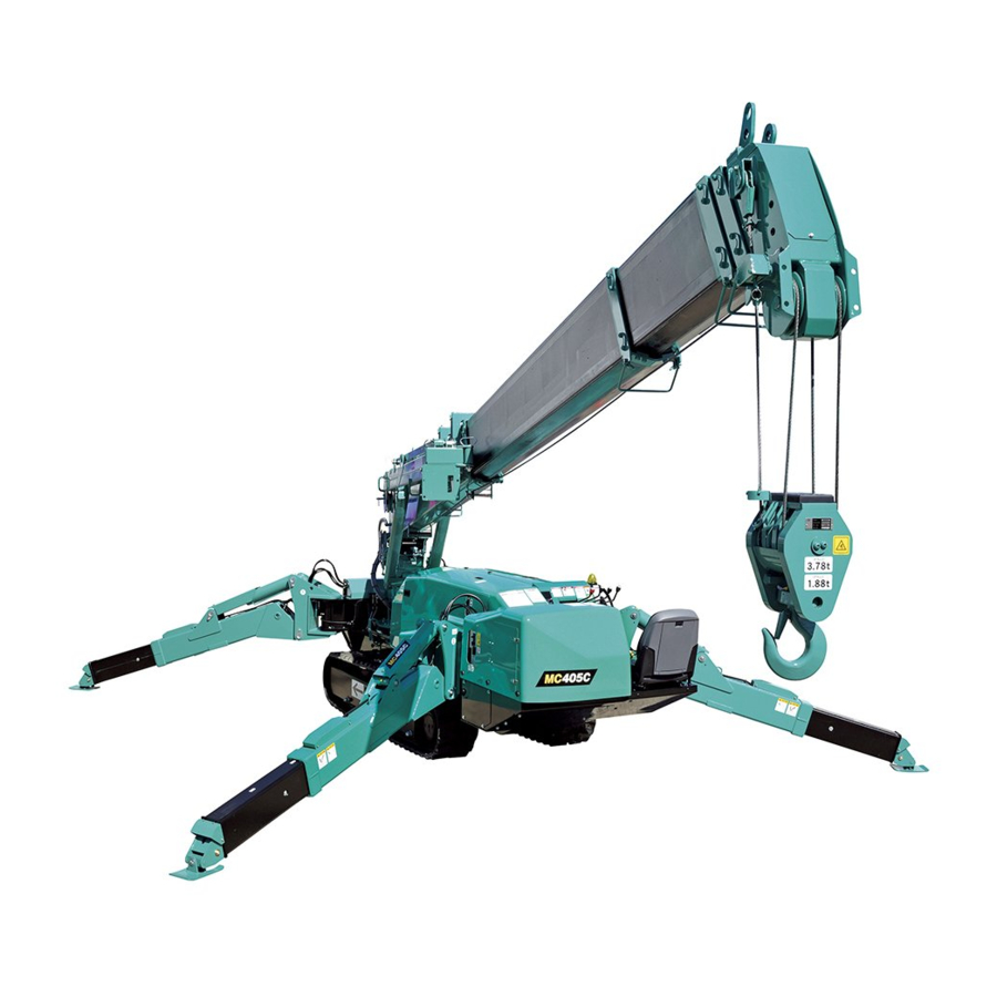
Mini-Crawler Crane
The parts numbers and lists written in this service manual are the
references for the services such as disassembling and assembling.
Be sure to ALWAYS refer to the latest parts catalog (the latest
information) before ordering any part, since the parts and the model
numbers are subject to change during the endless improvements and
changes of our Machine.
Advertisement
Table of Contents
Troubleshooting

Related Manuals for Maeda MC405C-3


Summary of Contents for Maeda MC405C-3
- Page 1 104ME-SM1910-00 Service Manual Mini-Crawler Crane The parts numbers and lists written in this service manual are the references for the services such as disassembling and assembling. Be sure to ALWAYS refer to the latest parts catalog (the latest information) before ordering any part, since the parts and the model numbers are subject to change during the endless improvements and changes of our Machine.
-
Page 3: Table Of Contents
CONTENTS Item Page GENERAL 1. SPECIFICATION DIMENSIONAL DRAWING 2. DIMENSIONAL DRAWING OF OUTRIGGER WIDTH 3. PRINCIPLE SPECIFICATION LIST 3.1 STANDARD SPECIFICATION 3.2 ENGINES AND ELECTRIC MOTER SPECIFICATION 4. WORKING RADIUS AND LIFTING HEIGHT 5. WORKING RADIUS AND LIFTING HEIGHT (PICK & CARRY) 6. -
Page 4: Item Page
Item Page 2.8 ELECTRIC POWERED LINE 2-42 [1] Hydraulic pump for electric operations - hydraulic pump for engine / hydraulic oil tank 2-43 3. TANK 2-44 3.1 HYDRAULIC TANK 2-44 3.2 FUEL TANK 2-46 3.2.1 FUEL LEVEL SENSOR 2-48 4. RETURN MANI-BLOCK 2-49 5. - Page 5 Item Page 9.3 PRECAUTIONS FOR USE 2-86 9.3.1 INSTALLATION 2-86 9.3.2 PIPING 2-86 9.3.3 LUBRICATING OIL FOR GEARS 2-87 9.3.4 GENERAL PRECAUTIONS 2-87 10. CRANE CONTROL VALVE 2-88 10.1 EXTERIOR VIEW AND SPECIFICATIONS 2-88 10.2 HYDRAULIC CIRCUIT DIAGRAM 2-89 10.3 RGB BLOCK 2-90 10.4 ACCELERATOR BLOCK 2-92...
- Page 6 Item Page 19.3.1 INNER PARTS 2-134 19.3.2 OPERATIONAL TEST 2-135 19.3.3 BASICS OF FUNCTIONALITY 2-135 19.3.4 TROUBLE SHOOTING 2-136 19.4 WINCH REDUCTION GEAR 2-138 19.5 OIL REPLACEMENT IN WINCH REDUCTION GEAR CASE 2-139 19.6 REPLACEMENT WINCH WIRE ROPE 2-142 20. SLEWING SYSTEM 2-144 20.1 EXTERIOR VIEW 2-144...
- Page 7 Item Page 2.3 BOOM STOWING POSITION DETECTOR 3-26 3. MOMENT LIMITER OVERVIEW AND FEATURES 3-28 4. EXTERNAL VIEW OF MOMENT LIMITER 3-30 4.1 DISPLAY UNIT 3-30 4.2 CONVERTER 3-31 5. BLOCK DIAGRAM 3-32 6. CONNECTOR DIAGRAM 3-33 7. CONNECTOR PIN ASSIGNMENT 3-34 7.1 CONVERTER CONNECTORS 3-34...
- Page 8 Item Page 21. POINTS FOR INPUT VOLTAGE MEASUREMENT OF EACH SENSOR 3-78 INTERACTIVE REMOTE CONTROL 1. INITIAL MODE SETTING PROCEDURE 1.1 BUTTON ARRANGEMENT ON CONTROL PANEL 1.2 ESTABLISHING INITIAL MODE: 1.3 INITIAL MODE FOR USER (A MODE) 1.4 INITIAL MODE FOR SERVICE (B MODE) 1.5 INITIAL MODE FOR MAKER (C MODE) 4-10 1.6 INITIAL MODE SETTING...
-
Page 9: General
GENERAL 1. SPECIFICATION DIMENSIONAL DRAWING 2. DIMENSIONAL DRAWING OF OUTRIGGER WIDTH 3. PRINCIPLE SPECIFICATION LIST 4. WORKING RADIUS AND LIFTING HEIGHT 5. WORKING RADIUS AND LIFTING HEIGHT (PICK & CARRY) 6. TOTAL RATED LOAD CHART 7. CRANE STANDARD PRESSURE AND OPERATING TIMETABLE 1-12 8. -
Page 10: Specification Dimensional Drawing
1. SPECIFICATION DIMENSIONAL DRAWING... -
Page 11: Dimensional Drawing Of Outrigger Width
2. DIMENSIONAL DRAWING OF OUTRIGGER WIDTH... -
Page 12: Principle Specification List
3. PRINCIPLE SPECIFICATION LIST 3.1 STANDARD SPECIFICATION System / Item MC405C-3 Machine mass 5600kg Overall length width height 4980mm 1380mm 1980mm Mass and Distance between idler and 2100mm dimensions sprocket Track gauge 1060mm Track width 320mm Maximum rated total load ... -
Page 13: Engines And Electric Moter Specification
3.2 ENGINES AND ELECTRIC MOTER SPECIFICATION System / Item MC405C-3 (Engine and Electric Motor Specifications) Machine mass 5750kg Overall length width height 4980mm 1380mm 1980mm Mass and Distance between idler and 2100mm dimensions sprocket Track gauge... - Page 14 System / Item MC405C-3 (Engine and Electric Motor Specifications) Model Yanmar 3TNV88F-EPMB Vertical in-line 3-cylinder, Water cooled, 4-cycle Type (Direct injection type) Engine Displacement 1.642L (1642cc) Rated output (continuous) 17.5 kW/2400min-1 (23.8 PS/2400rpm) Fuel tank capacity Diesel fuel/ 60L 115D31R (DC12V 1 piece)
-
Page 15: Working Radius And Lifting Height
4. WORKING RADIUS AND LIFTING HEIGHT... -
Page 16: Working Radius And Lifting Height (Pick & Carry)
5. WORKING RADIUS AND LIFTING HEIGHT (PICK & CARRY) -
Page 17: Total Rated Load Chart
6. TOTAL RATED LOAD CHART [1] TOTAL RATED LOAD CHART AT WIRE ROPE 4 FALLS * The rated total load is a load including the mass of a hoisting accessory (hook: 50kg). OUTRIGGER EXTENDED TO MAXIMUM BOOM (1)/BOOM (1)+(2) BOOM (1)+(2)+(3) BOOM (1)+(2)+(3)+(4) BOOM (1)+(2)+(3)+(4)+(5) Working... -
Page 18: Total Rated Load Chart At Wire Rope 2 Falls
[2] TOTAL RATED LOAD CHART AT WIRE ROPE 2 FALLS * The rated total load is a load including the mass of a hoisting accessory (hook: 50kg). OUTRIGGER EXTENDED TO MAXIMUM BOOM (1)/BOOM (1)+(2) BOOM (1)+(2)+(3) BOOM (1)+(2)+(3)+(4) BOOM (1)+(2)+(3)+(4)+(5) Working Total rated Working... -
Page 19: Total Rated Load Chart At Wire Rope Single Fall
[3] TOTAL RATED LOAD CHART AT WIRE ROPE SINGLE FALL * The rated total load is a load including the mass of a hoisting accessory (hook: 20kg). OUTRIGGER EXTENDED TO MAXIMUM BOOM (1)/BOOM (1)+(2) BOOM (1)+(2)+(3) BOOM (1)+(2)+(3)+(4) BOOM (1)+(2)+(3)+(4)+(5) Working Total rated Working... -
Page 20: Crane Standard Pressure And Operating Timetable
7. CRANE STANDARD PRESSURE AND OPERATING TIMETABLE 7.1 OUTRIGGER (OIL TEMPERATURE 30 to 50°C) Accelerator full Operating Operating time Operating time pressure (MPa) (sec) (sec) (at travel valve) Engine Electric motor Extension 15 ± 2 16 ± 2 Front outrigger slide Single Contraction 15 ±... -
Page 21: Power Train Drawing
8. POWER TRAIN DRAWING 21.5MPa (220kgf / cm 1-13... - Page 22 This Page Intentionally Left Blank. 1-14...
-
Page 23: Construction & Maintenance
CONSTRUCTION & MAINTENANCE 1. HYDRAULIC CIRCUIT DIAGRAM 2. HYDRAULIC PIPING DIAGRAM 3. TANK 2-44 4. RETURN MANI-BLOCK 2-49 5. CHECK VALVE 2-50 6. ENGINE ASSEMBLY 2-52 7. HYDRAULIC PUMP 2-70 8. TRAVEL CONTROL VALVE 2-74 9. TRAVELING MOTOR 2-78 10. CRANE CONTROL VALVE 2-88 11. - Page 24 This Page Intentionally Left Blank.
- Page 25 1. HYDRAULIC CIRCUIT DIAGRAM 21.5MPa (220kgf / cm 21.5MPa (220kgf / cm...
- Page 26 This Page Intentionally Left Blank.
-
Page 27: Hydraulic Units Layout Diagram
1.1 HYDRAULIC UNITS LAYOUT DIAGRAM... - Page 29 This Page Intentionally Left Blank.
-
Page 30: Hydraulic Piping Diagram
2. HYDRAULIC PIPING DIAGRAM 2.1 CRANE ROTATING PARTS (rotary joint - winch / derricking / telescopic cylinder) - Page 31 Name Qty. Note Long connector (3/8) Part No.: 349-4412500 Male 90° elbow with plate 1071-06 Part No.: 22611-11150 TA hydraulic hose N3000-06 × 1720L SC-PF (O-ring) × SF-PF Part No.: 22757V65172 TB hydraulic hose N3000-06 × 1770L SC-PF (O-ring) × SF-PF Part No.: 22757V65177 Male 90°...
-
Page 32: Crane Fixed Parts (Crane Control Valve - Rotary Joint / Slewing Motor)
2.2 CRANE FIXED PARTS (crane control valve - rotary joint / slewing motor) 2-10... - Page 33 Name Qty. Note DA hydraulic hose down KG06 C-C × 2950L Part No.: 22782-85295 DB hydraulic hose down KG06 C-C × 2950L Part No.: 22782-85295 WA hydraulic hose down KG06 C-C × 3050L Part No.: 22782-85305 TA hydraulic hose down KG06 C-C ×...
- Page 34 Joint Hose/Piping Joint Equipment Connection Port Port Name Name Name name destination Part No. Part No. Part No. Male 45° elbow DA hydraulic hose with plate up (raise) 22611-11250 22782H85075 (Raise) “1072-06 “KG06 C-C × HYDEX” 750L” DB hydraulic hose up (lower) (Lower) 22782H85069...
- Page 35 Joint Hose/Piping Joint Equipment Connection Port Port Action Name Name Name name destination No. Mark Part No. Part No. Part No. DA hydraulic hose down Male connector (raise) (Raise) (DB) Raising 22782-85295 22611-11050 “KG06 C-C × 2950L” “1067-06 HYDEX” DB hydraulic hose down Male connector (lower) (Lower)
-
Page 36: Travel Line (Travel Control Valve - Terminal Assembly - Travel Motor)
2.3 TRAVEL LINE (travel control valve - terminal assembly - travel motor) 2-14... - Page 37 Name Qty. Note R hose 1 KG08 C-C × 2900L (with film) Part No.: 22782H86290 R hose 2 KG08 C-C × 2900L (with film) Part No.: 22782H86290 R hose 3 KG08 C-C × 3050L (with film) Part No.; 22782H86305 R hose 4 KG08 C-C ×...
-
Page 38: Outrigger Lines
2.4 OUTRIGGER LINES 2-16... - Page 39 2-17...
- Page 40 Name Qty. Note OR pipe Slide FRA Part No.: S104R4044000 OR pipe Slide FRB Part No.: S104R4045000 OR pipe Extension FRA Part No.: S104R4046000 OR pipe Extension FRB Part No.: S104R4047000 OR pipe Slide FLA Part No.: S104R4048000 OR pipe Slide FLB Part No.: S104R4049000 OR pipe Extension FLA Part No.: S104R4050000...
- Page 41 Name Qty. Note Gall 50 Part No.: 103-4531800 Gall 3 Part No.: 349-4400200 Gall 4 Part No.: 103-4531900 Hexagon head bolt with washer M6 × 1.0 × 25L Part No.: 21A12M06025 Hexagon head bolt with washer M6 × 1.0 × 55L Part No.: 21A12M06055 Hexagon head bolt M10 ×...
-
Page 42: Outrigger Control Valve - Or Select Valve - Or / Slide Cylinder Fr Out (Front Right Side Out)
[1] Outrigger control valve - OR select valve - OR / Slide cylinder FR out (front right side out) Joint Hose/Joint/Piping Joint Equipment Connection Port Port Name Name Name name destination Part No. Part No. Part No. Male connector OR hose FRA Outrigger control valve 22611-11050... -
Page 43: Outrigger Control Valve - Or Select Valve - Or / Slide Cylinder Fr In (Front Right Side In)
[2] Outrigger control valve - OR select valve - OR / Slide cylinder FR in (front right side in) Joint Hose/Joint/Piping Joint Equipment Connection Port Port Name Name Name name destination Part No. Part No. Part No. Outrigger control Male connector OR hose FRB valve 22611-11050... -
Page 44: Outrigger Control Valve - Or Select Valve - Or / Slide Cylinder Fl Out (Front Left Side Out)
[3] Outrigger control valve - OR select valve - OR / Slide cylinder FL out (front left side out) Joint Hose/Joint/Piping Joint Equipment Connection Port Port Name Name Name name destination Part No. Part No. Part No. Outrigger control Male connector OR hose FLA valve 22611-11050... -
Page 45: Outrigger Control Valve - Or Select Valve - Or / Slide Cylinder Fl In (Front Left Side In)
[4] Outrigger control valve - OR select valve - OR / Slide cylinder FL in (front left side in) Joint Hose/Joint/Piping Joint Equipment Connection Port Name Name Name name destination Part No. Part No. Part No. Outrigger Male connector OR hose FLB control valve 22611-11050 22782-85320... -
Page 46: Outrigger Control Valve - Or Select Valve - Or / Slide Cylinder Rr Out (Rear Right Side Out)
[5] Outrigger control valve - OR select valve - OR / Slide cylinder RR out (rear right side out) Joint Hose/Joint/Piping Joint Equipment Connection Port Port Name Name Name name destination Part No. Part No. Part No. Male 90° elbow Male connector OR hose RRA OR select valve... -
Page 47: Outrigger Control Valve - Or Select Valve - Or / Slide Cylinder Rr In (Rear Right Side In)
[6] Outrigger control valve - OR select valve - OR / Slide cylinder RR in (rear right side in) Joint Hose/Joint/Piping Joint Equipment Connection Port Port Name Name Name name destination Part No. Part No. Part No. Mail 90° elbow with Male connector OR hose RRB Outrigger... -
Page 48: Outrigger Control Valve - Or Select Valve - Or / Slide Cylinder Rl Out (Rear Left Side Out)
[7] Outrigger control valve - OR select valve - OR / Slide cylinder RL out (rear left side out) Joint Hose/Joint/Piping Joint Equipment Connection Port Port Name Name Name name destination Part No. Part No. Part No. Male 90° elbow with Male connector OR hose RLA Outrigger... -
Page 49: Outrigger Control Valve - Or Select Valve - Or / Slide Cylinder Rl In (Rear Left Side In)
[8] Outrigger control valve - OR select valve - OR / Slide cylinder RL in (rear left side in) Joint Hose/Joint/Piping Joint Equipment Connection Port Port Name Name Name name destination Part No. Part No. Part No. Mail 90° elbow Outrigger Male connector OR hose RLB... -
Page 50: Pump Line
2.5 PUMP LINE (P line) 2-28... - Page 51 Name Qty. Note HN-1040 (φ40 × R1・1/2) Part No.: 103S98300000 Hose nipple (barb fitting) R1・1/2 × Rc1・1/2 (Low pressure) Part No.: 22011-04BB0 Street elbow Rc1・1/2 (Low pressure) Part No.: 22011-03BBB Plug R1・1/2 (Low pressure) Part No.: 22011-55B00 Suction hose 740L 136-244-40 ×...
-
Page 52: Hydraulic Oil Tank - Pump
[1] Hydraulic oil tank - Pump Joint Hose/Piping Joint Connection Equipment name Port Port Name Name Name destination Part No. Part No. Part No. To electric line (6) blanking plug 22011-03BBB Hydraulic oil tank “Rc1・1/2 (Low 22011-55B00 (104-2157300) “R1・1/2 (Low pressure)”... - Page 53 [3] Travel control valve - crane control valve / merge valve - OR control valve Joint Hose/Piping Joint Connection Equipment name Port Port Name Name Name destination Part No. Part No. Part No. Flareless type joint Pipe CO1 18. Terminal (with O-ring) Travel control valve assembly...
-
Page 54: Tank / Drain Line
2.6 TANK / DRAIN LINE (T/Dr line) 2-32... - Page 55 Name Qty. Note Return hose CV1 PA0316 CR9-CR4 × 1710L (full length spiral) Part No.: 104-4739200 Return hose CV2 PA0312 CR9-CR4 × 1440L (full length spiral) Part No.: 104-4739300 Return hose RF PA0316 C-CR9 × 530L (full length spiral) Part No.: 104-4742300 Return hose OC IN PA0316 C-C ×...
-
Page 56: Crane Control Valve - Manifold Block - Oil Cooler - Tank (Return Filter)
[1] Crane control valve - manifold block - oil cooler - tank (return filter) Joint Hose/Piping Joint Connection Equipment name Port Port Name Name Name destination Part No. Part No. Part No. O-ring boss female connector Crane control valve (S104G3658000) 22611-11860 “1068-08”... -
Page 57: Travel Motor - Terminal B - Hydraulic Oil Tank
[3] Travel motor - terminal B - hydraulic oil tank Joint Hose/Piping Joint Equipment Connection Port Port Name Name Name name destination Part No. Part No. Part No. Travel drain hose Male connector Male connector R, L Left travel motor 33. -
Page 58: Merge Valve - Speed Increase Valve - Hydraulic Oil Tank
[5] Merge valve - speed increase valve - hydraulic oil tank Joint Hose/Piping Joint Connection Equipment Port Port Name Name Name name destination Part No. Part No. Part No. Bushing Merge valve 22051-08303 (349S51400001) “9/16-18-UNFxRc1/4” Barb fitting Drain hose V Barb fitting 33. - Page 59 This Page Intentionally Left Blank. 2-37...
-
Page 60: Pilot Line
2.7 PILOT LINE 2-38... - Page 61 Name Qty. Note Hydraulic hose PP1 SPL04 C-C × 1080L (with film) Part No.: 22788H83108 Hydraulic hose PP2 SPL04 C-C × 1000L (with film) Part No.: 22788H83100 Travel PLT hose KF04 C-C × 1650L (with film) Part No.: 22781H83165 Travel PLT hose R, L KF04 C-C ×...
-
Page 62: Crane Control Valve - Or Control Valve - Merge Valve
[1] Crane control valve - OR control valve - merge valve Joint Hose/Piping Joint Connection Equipment name Port Port Name Name Name destination Part No. Part No. Part No. O-ring boss female connector Crane control valve (S104G3658000) 22611-11830 “1068-04” Male 90° elbow Hydraulic hose PP1 One-side male tee 22788H83108... - Page 63 This Page Intentionally Left Blank. 2-41...
-
Page 64: Electric Powered Line
2.8 ELECTRIC POWERED LINE 2-42... -
Page 65: Hydraulic Pump For Electric Operations - Hydraulic Pump For Engine / Hydraulic Oil Tank
Name Qty. Note HN-1040 (φ40 × R1・1/2) Part No.: 103S98300000 Hose nipple (barb fitting) Street elbow Rc1・1/2 × R1・1/2 (Low pressure) Part No.: 22011-04990 Suction hose 136-244-40 × 1650L (Type S) Part No.: 104S98000000 Hose band ABA Hose clip 44-56 Part No.: 103S97800000 Male 45°... -
Page 66: Tank
3. TANK 3.1 HYDRAULIC TANK 2-44... - Page 67 Name Qty. Note Hydraulic tank Part No.: 104-2157300 Suction filter assembly Part No.: 103S94300000 Suction cap Part No.: 103-3348200 O-ring Type-1 A, P18 Part No.: 26210-10181 Sems bolt M8 × 1.25 × 20L (plated) Part No.: 01024-80820 Band assembly Part No.: 104-3340400 Heat insulator (left) Part No.: 104-3267100 Trim seal...
-
Page 68: Fuel Tank
3.2 FUEL TANK 2-46... - Page 69 Name Qty. Note Fuel tank Part No.: 104-2157400 O-ring 1A-P14 (For G3/8) Part No.: 26210-10141 Plug G3/8 equivalent Part No. 22611-13350 Strainer Part No.: 4700-69000-0 Cap assembly Part No.: 4700-70000 Packing Part No.: 353-4438700 Fuel sender assembly Part No.: 103S93100000 Cross recessed head screw with M5 ×...
-
Page 70: Fuel Level Sensor
3.2.1 FUEL LEVEL SENSOR Q’ty Q’ty Q’ty Description Description Description Mounting plate Hex. nut Philp head screw Die cast body Spring washer Spring washer Skipped No. Contact bolt Rvc wire Tank wire Plane washer Rivet Float Washer Insualted washer Terminal Plane washer Terminal clip Extension bracket... -
Page 71: Return Mani-Block
4. RETURN MANI-BLOCK Each ports connection Port size Crane control valve t1 port Oil cooler inlet Outrigger control valve v port PF3/4 Travel control valve t port Hydraulic tank outlet Oil cooler outlet Q’ty Description Notice System block F-2460B Check valve DE-CVA-00-0070 Specifications Max. - Page 72 5. CHECK VALVE Q’ty Description Notice Body Maker Parts No.: 01113-10100 Port thread size: PT1/2 Plunger Maker Parts No.: 01113-10200 Compression spring Maker Parts No.: 01113-10300 Plane washer Maker Parts No.: 083007-02100 Snap ring Maker Parts No.: 084300-01018 Specifications Rated flow capacity 70 L / min Rated oil pressure 20.59 MPa (210 kgf / cm...
- Page 73 This Page Intentionally Left Blank. 2-51...
-
Page 74: Engine Assembly
6. ENGINE ASSEMBLY 6.1 ENGINE ASSEMBLY 3TNV88F-EPMB Yanmar 2-52... -
Page 75: Engine Model
6.2 ENGINE MODEL Engine name 3TNV88F-EPMB ARB-OR-Tier4 / EPA Tier4 / EC StageV / Applicable emission control 3rd Construction Machinery Designation / Korean regulations Engine type Vertical in-line water-cooled 4 stroke diesel engine (direct injection type) Number of cylinders - Bore × Stroke 3-φ88 ×... -
Page 76: Name Of Each Section
6.3 NAME OF EACH SECTION 2-54... -
Page 77: Certification Name Plate
6.4 CERTIFICATION NAME PLATE 6.4.1 EMISSION CONTROL CERTIFICATION NAME PLATE Emission control is applied all over the world. For this reason, it is necessary to clarify which regulations each engine complies with. The drawing on the right shows name plates placed on engines. 2-55... -
Page 78: Diesel Fuel
6.5 DIESEL FUEL 6.5.1 FUEL SYSTEM ( BALL-TYPE SWIRT CHAMBER 6.5.2 USE OF ADEQUATE FUELS Use poor quality fuels may cause defects as described below. Instruct users for use of adequate fuels. 1. Deposit to Exhaust Valves Deposit to exhaust valves may cause compression defect, incomplete combustion and/or poor fuel consumption efficiency, as well as, mixture of incineration residue of fuel into exhaust gas and corrosion of exhaust valve seats. -
Page 79: Diesel Fuel Specifications
6.5.3 DIESEL FUEL SPECIFICATIONS Diesel fuel should comply with the following specifications. The table lists several worldwide specifications for diesel fuels Diesel Fuel Specification Location JIS K2204 Grade No. 2 Japan No.2-D, No.1-D, ASTM D975-94 EN590: 96 European Union ISO 8217 DM X International BS 2869-A1 or A2 United Kingdom... -
Page 80: Priming The Fuel System
[Precautions and concerns regarding the use of bio-fuels] 1. Free methanol in FAME may result in corrosion of aluminum and zinc FIE components. 2. Free water in FAME may result in plugging of fuel filters and increased bacterial growth. 3. High viscosity at low temperatures may result in fuel delivery problems, injection pump seizures, and poor injection nozzle spray atomization. - Page 81 This Page Intentionally Left Blank. 2-59...
-
Page 82: Coolant
6.6 COOLANT 6.6.1 COOLANT SYSTEM 6.6.2 USE OF ADEQUATE COOLANT Contaminants contained in coolant may deposit sludges to internal surface of engine and/or radiator or rust those. Further, that prevents correct heat conductivity or circulation of coolant, thus, poor cooling and engine overheat may result, Drain coolant and wash interior of cooling system with cleaning solution every 1,000 hours of operation or annually. -
Page 83: Lubricating Oil
6.7 LUBRICATING OIL 6.7.1 LUBRICATING SYSTEM 6.7.2 USE OF ADEQUATE LUBRICANT Use of adequate Lubrication Oil shall facilitate: 1. Reducing attrition of friction area in Engine. 2. Preventing rust and corrosion of Engine area. 3. Cooling of heat area in Engine. 4. -
Page 84: Engine Oil Specifications
6.7.3 ENGINE OIL SPECIFICATIONS Use an engine oil that meets or exceeds the following guidelines and classifications: [Service Categories] ・API Service Categories CD or higher ・ACEA Service Categories E-3, E-4, and E-5 ・JASO Service Categories DH-1 [Definitions] ・API Classification (American Petroleum Institute) ・ACEA Classification (Association des Constructeurs Europeens d’Automobilies) ・JASO (Japanese Automobile Standards Organization) [Additional Technical Engine Oil Requirements]... -
Page 85: Periodic Maintenance Schedule
6.8 PERIODIC MAINTENANCE SCHEDULE Instruct your users to follow schedule of Engine Periodic Maintenance as listed below: ○: Check ◇: replace ●: Contact your authorized Ynmar industrial engine dealer or distributor Periodic Maintenance Interval Every Every Every Every Every Every System Check Item Daily... -
Page 86: Trouble Shooting
6.9 TROUBLE SHOOTING This table is a summary of general disorders and causes. It is strongly advised to take adequate actions to prevent serious accidents whenever an indication of any disorder is detected: Disorders at Engine Exhaust Hunting Disorders Starting Power Down Engine Exhaust... - Page 87 Lubricating Oil Intake Coolant Counter-action ○ ○ Adjust valve clearance ○ ○ ○ ○ Valve seat fitting ○ ○ ○ ○ Repair or replace intake and exhaust valve ○ ○ Replace gasket ○ ○ ○ ○ ○ ○ Replace Piston Ring ○...
- Page 88 Engine Exhaust Disorders at Starting Hunting Disorders Power Down Engine stall Exhaust Gas Operat. Smoke Cause Fuel Injection Pump Timing, too ○ ○ ○ early Fuel Injection Pump Timing, too ○ ○ ○ ○ late ○ ○ ○ ○ ○ Improper fuel Leakage of Water into Fuel ○...
- Page 89 Lubricating Oil Coolant Intake Counter-action ○ Check and adjust ○ ○ Check and adjust Replace to adequate fuel Drain fuel filter Clean or replace Air bleed Clean or replace Check fuel filter and feed pump ○ ○ Check and adjust ○...
-
Page 90: Fuel Piping
6.10 FUEL PIPING 2-68... - Page 91 Name Qty. Note Yokohama fuel hose Nominal size φ8 × φ15 × 1350L Part No.: Fuel hose 1 22823-31350 Yokohama fuel hose Nominal size φ8 × φ15 × 490L Part No.: Fuel hose 2 22823-30490 Yokohama fuel hose Nominal size φ8 × φ15 × 405L Part No.: Fuel hose 3 22823-30405...
-
Page 92: Hydraulic Pump
7. HYDRAULIC PUMP 7.1 HYDRAULIC PUMP FOR ENGINE Type: PVD-1B-34-5933A 7.1.1 APPEARANCE AND SPECIFICATIONS S104I4129000 Specifications Pump capacity P1+P2 : 17+17 cc/rev Oil used ISO VG 32, 46, 68 Oil temperature range -20 to 80°C P1: 21.5 Mpa (219 kg/cm Maximum pressure Hydraulic fluid pollution P2: 21.5 MPa (219 kg/cm... -
Page 93: Hydraulic Pump For Electric Operations
7.2 HYDRAULIC PUMP FOR ELECTRIC OPERATIONS Type: PVD-1B-26-4309A 7.2.1 APPEARANCE AND SPECIFICATIONS 306S32500001 Specifications Pump capacity P1+P2 : 13+13 cc/rev Oil used ISO VG 32, 46, 68 Oil temperature range -20 to 100°C P1: 21.5 Mpa (219 kg/cm Maximum pressure Hydraulic fluid pollution P2: 21.5 MPa (219 kg/cm Within NAS level 11... -
Page 94: Trouble Shooting
7.3 TROUBLE SHOOTING Disorders Cause Counter-action ・ Engine revolution rate is higher than the ・ Adjust to prescribed rate. prescription. ・ Adjust to prescribed rate. Engine, Over load ・ Pressure is higher than the prescription. ・ Repair or replace ・ Pump components, seizure or damage. Hydraulic oil discharge amount is ・... - Page 95 This Page Intentionally Left Blank. 2-73...
-
Page 96: Travel Control Valve
8. TRAVEL CONTROL VALVE 8.1 EXTERIOR VIEW AND SPECIFICATIONS Each Ports Connection Port Size Each Ports Connection Port Size Pump P2 Port PF1/2 Left Travel Motor A Port (Forward) PF3/8 Pump P1 Port PF1/2 Left Travel Motor B Port (Reverse) PF3/8 Return PF1/2... -
Page 97: Inner Parts
8.2 INNER PARTS Q’ty Q’ty Q’ty Description Description Description Compression spring Spring cover Screw (M10 × 14) Needle valve Tie rod Nut (M8) Cap nut Inlet housing Rivet Gasket Inlet housing O-ring (1A-P12) Spring holder Plug O-ring (1B-P8) Compression spring Plunger housing O-ring (1B-P9) Seal holder... -
Page 98: Inspection And Adjustment
8.3 INSPECTION AND ADJUSTMENT [1] PARTS INSPECTION Assembly Criteria Counter-action ・ Scratch, rust and/or corrosion in spool sliding area. ・ Replace ・ Scratch, rust and/or corrosion in seal pocket of spool insertion. ・ Replace ・ Housing ・ Scratch, rust and/or corrosion in port seal area next to O-ring. ・... -
Page 99: Trouble Shooting
8.4 TROUBLE SHOOTING Each Item shown in the table below indicates only individual problem, however, troubles may be caused by multiple problems, in many cases. It is advisable to check one by one for efficient trouble shooting. Disorders Cause Counter-action ・... -
Page 100: Traveling Motor
9.TRAVELING MOTOR 9.1 EXTERIOR VIEW AND SPECIFICATIONS Left Traveling Motor Right Traveling Motor A Port Reverse B Port Reverse B Port Forward A Port Forward Specifications Specifications Of Reduction Gear Max. Output Torque 4766 N・m (486 kgf・m) Max. Output Revolution 35.0 / 57.8 min Reduction Ratio 1 / 47.53... -
Page 101: Inner Parts
9.2 INNER PARTS Description Description Description Oil filler plug Valve plate No.1 sun gear Cover Brake valve No.2 planetary carrier No.2 planetary gear Brake piston Drain plug No.2 sun gear Plate Oil level plug Ring gear Disk Check valve Ball Shaft Counter balance valve Housing... -
Page 102: Basics Of Functionality
9.2.2 BASICS OF FUNCTIONALITY 1. Low Speed Travel (Motor Swash Plate Angle is Maximum) ・ Pressurized oil shall not flow from travel control valve to PP port since acceleration valve (1) is demagnetized. ・ Pressurized oil shall not flow from travel control valve to PP port since automatic control valve (2) is pressed downward by Spring (3). - Page 103 2. High Speed Travel (Motor Swash Plate Angle is Minimum) ・Pressurized oil shall flow from travel control valve to PP port since acceleration valve (1) is magnetized. ・Automatic control valve (2) compresses spring (3) and actuate to connect circuit to control chamber “a”. ・Main pressurized oil which is regulated by travel lever enters into control chamber “a”...
-
Page 104: Function Of Automatic Control Valve
9.2.3 FUNCTION OF AUTOMATIC CONTROL VALVE 1. Automatic Travel Speed Control from High to Low ・ When shift switch is turned to “High Speed Travel” and machine is traveling in high speed, pressure to actuate motor (Pc) is introduced into chamber (a) and chamber (b) of automatic control valve. ・... - Page 105 2. Automatic Travel Speed Control from Low to High ・ When shift switch is turned to “Low Speed Travel” and machine is traveling in low speed, pressure to actuate motor (Pc) is introduced into a chamber (a) of automatic control valve (1), (when chamber (b) is connected to DR port). ・...
-
Page 106: Function Of Counter Balance Valve
9.2.4 FUNCTION OF COUNTER BALANCE VALVE 1. Function of Feed Mode When travel lever is operated, pressurized oil shall be fed to A port from control valve which opens check valve (1). Pressurized oil flows from motor intake port MA to motor exit valve MB. On the other hand, pressurized oil, entered into chamber (D) through orifice (C) shall push back tension of spring (2) and actuate spool (3) rightward. -
Page 107: Function Of Parking Brake
9.2.5 FUNCTION OF PARKING BRAKE 1. Operation while Traveling When traveling lever is actuated, pressurized oil from pump enters into chamber (A) of brake piston (1) and pushes it rightward. Consequently, pressure from spring (4) to plate (2) and disk (3) is reduced and allows plate (2) to release disk (3). -
Page 108: Precautions For Use
9.3 PRECAUTIONS FOR USE 9.3.1 INSTALLATION 1. Fitting Area (Ref. Figure, right) Fitting A to Sprocket: 210h8 (0 / -0.072) Fitting B to Body: 165h8 (0 / -0.063) 2. To install Motor to Body and/or to install Sprocket to Motor, use mount bolts and fix them mildly, but avoid tapping by hammers. -
Page 109: Lubricating Oil For Gears
9.3.3 LUBRICATING OIL FOR GEARS 1. Use diesel oil class “SAE30-CD” or equivalent for lubricating oil. (Apollo Diesel Motive S-330 of Idemitsu Kosan is used at delivery of our cranes.) 2. It is user’s option to select lubricating oil from any other recommended products; however it is not advisable to mix different brands 3. -
Page 110: Crane Control Valve
10. CRANE CONTROL VALVE 10.1 EXTERIOR VIEW AND SPECIFICATIONS Each Ports Connection Port Size Each Ports Connection Port Size Travel Control Valve (CO1) PF1/2 Return PF1/2 Derrick Cylinder Bottom (Boom Raise) PF3/8 Telescopic Cylinder Head (Boom Retract) PF3/8 Derrick Cylinder Head (Boom Lower) PF3/8 Telescopic Cylinder Bottom (Boom Extend) PF3/8... -
Page 111: Hydraulic Circuit Diagram
10.2 HYDRAULIC CIRCUIT DIAGRAM 21.5 MPa 220 kgf / cm 2-89... -
Page 112: Rgb Block
10.3 RGB BLOCK 2-90... - Page 113 1. Back Pressure Valve Back pressure valve secures minimum pressure rate of hydraulic oil to actuate control cylinder. 2. Reducing Valve Reducing valve reduces pressure rate of hydraulic oil to control cylinder to proper level. 3. Main Relief Valve Main relief valve regulates maximum pressure of pump circuit. 4.
-
Page 114: Accelerator Block
10.4 ACCELERATOR BLOCK 10.5 FUNCTION BLOCK (DERRICK, WINCH, TELESCOPIC, SLEWING) 2-92... -
Page 115: Solenoid Valve Functioning Principle
10.6 SOLENOID VALVE FUNCTIONING PRINCIPLE These figures are for the purpose to illustrate basics of functionality of solenoid valves. Solenoid valves SA and SB for control valve are the same in their basics of functionality. 1. Unmagnetized conditions 2. Magnetized conditions Circuit to control cylinder is interrupted. - Page 116 Computation of Deviations and Pulse Width Hydraulic unit is controlled as follows: 1. When control is out, a transistor in the receiver is “OFF” and solenoid valves are attached to a tank. In this condition control cylinder is held in neutral position by spring tension.
- Page 117 This Page Intentionally Left Blank. 2-95...
-
Page 118: Outrigger Control Valve
11. OUTRIGGER CONTROL VALVE 11.1 EXTERIOR VIEW AND SPECIFICATIONS Each Ports Connection Port Size Each Ports Connection Port Size Confluence Select Valve Port A PF1/2 OR Selector valve (1) Port P1 (Out) PF3/8 Return PF1/2 OR Selector valve (1) Port P2 (In) PF3/8 OR Selector valve (3) Port P1 (Out) PF3/8... - Page 119 Circuit Diagram Specifications Max. Common Use Pressure 20.6 MPa (210 kgf/cm Rated Flow Capacity 50 L/min Relief Setting Pressure 2.94 - 24.5 MPa (30 - 250 kgf/cm 1.27 - 1.67 MPa (13 – 17 kgf/cm Back Pressure Valve Setting Pressure 1.18 - 1.57 MPa (12 –...
-
Page 120: Inner Parts
11.2 INNER PARTS Tightening Torque Table DESCRIPTION Q’TY Portion Tightening Torque Thread Size Inlet Section Mounting Bolt 19.6±0.98 N・m Block (Outrigger 1, 3, 4) Spool (Outrigger 1, 3, 4) 18.6±0.98 N・m Spool End and Connecting End Block (Outrigger 2) Coat Lock-tight #242 Spool (Outrigger 2) Solenoid Mounting Bolt 2.45 - 3.43 N・m... - Page 121 This Page Intentionally Left Blank. 2-99...
-
Page 122: Outrigger Select Valve
12. OUTRIGGER SELECT VALVE 12.1 EXTERIOR VIEW AND SPECIFICATIONS Each Ports Connection Port Size Outrigger Control Valve Port A PF1/4 Outrigger Control Valve Port B PF1/4 Outrigger Slide Cylinder Bottom (Extension Out) PF1/4 Outrigger Cylinder Bottom (Grounding Out) PF1/4 Outrigger Cylinder Head (Grounding In) PF1/4 Outrigger Slide Cylinder Head (Extension In) PF1/4... -
Page 123: Inner Parts
12.2 INNER PARTS Q’ty Description Solenoid block Repair kit ・Cap ・O-ring (14.00) ・O-ring (29.87) Cap set Main block 2-101... -
Page 124: Crane Circuit Confluence Valve
13. CRANE CIRCUIT CONFLUENCE VALVE 13.1 EXTERIOR VIEW and SPECIFICATIONS Each Ports Connection Port Size Travel Control Valve (CO2) 7/8-14 UNF Outrigger Control Valve Port P 7/8-14 UNF Crane Control Valve Port P1 7/8-14 UNF Travel Control Valve (CO1) Outrigger Control Valve Port GP 9/16-18 UNF Crane Control Valve Port PP1 Drain... -
Page 125: Inner Parts
13.2 INNER PARTS Q’ty Q’ty Q’ty Description Description Description Plug Compression spring Rivet Compression spring Body Steel ball Sleeve Spool O-ring (1A-P16) Spool Skipped No. O-ring (1B-P14) Solenoid Flange plug (PF3/8) O-ring (AS568-906) Name plate Hex. socket head bolt (M5 × 10) Plug (NPTF1/16) Stopper Plane washer (M5) -
Page 126: Inspection And Adjustment
13.3 INSPECTION AND ADJUSTMENT [1] PARTS INSPECTION Assembly Criteria Counter-action ・ Damage to solenoids, including short-circuit and wire breakage. ・ Replace ・ Coil Assembly ・ Short-circuit and wire breakage. ・ Replace ・ Scratch, rust and/or corrosion in spool sliding area. ・... - Page 127 This Page Intentionally Left Blank. 2-105...
-
Page 128: Traveling Speed Select Valve
14. TRAVELING SPEED SELECT VALVE 14.1 EXTERIOR VIEW AND SPECIFICATIONS Each Ports Connection Port Size Travel Control Valve Pressure Pick-up Port PF1/4 Left and Right Traveling Motors Port PP PF1/4 Drain PF1/4 Q’ty Q’ty Q’ty Description Description Description Plug Solenoid Rivet Body Name plate... -
Page 129: Inspection And Adjustment
14.2 INSPECTION AND ADJUSTMENT [1] PARTS INSPECTION Assembly Criteria Counter-action ・ Damage to solenoids, including short-circuit and wire breakage. ・ Replace ・ Coil Assembly ・ Short-circuit and wire breakage. ・ Replace ・ Scratch, rust and/or corrosion in spool sliding area. ・... -
Page 130: Rotary Joint
15. ROTARY JOINT 15.1 EXTERIOR VIEW AND SPECIFICATIONS 2-108... -
Page 131: Inner Parts
Rotary Joint Connection Table Thread Thread Stamp Upper Side Connecting Hose Stamp Lower Side Connecting Hose Size Size (Boom Retract) PF3/8 TB Hose (Crane Valve Port A3) PF3/8 TB Hose (Telescopic Cylinder Head Port) TA Hose (Telescopic Cylinder Bottom Port) (Boom Extend) PF3/8 TA Hose (Crane Valve Port B3) PF3/8... -
Page 132: Hook Block
16. HOOK BLOCK 2-110... - Page 133 Q’ty Description Notice Hook block Sheave pin Hook Hook nut Sheave Sheave collar (N) Stopper aplate Top guard Top plate Thrust bearing 51206 Spring pin 5 × 45 L Hex. socket head button bolt M10 × 22L (Plating) 8.8T Spring washer M10 (Plating) Hex.
-
Page 134: Hook Block Inspection
16.1 HOOK BLOCK INSPECTION The hook block is one of the important maintenance parts. Check by the following procedure and be sure to always use under safe condition. Repair or replace immediately whenever any defect is found as result of the inspection. Replacement requires a modification inspection prior. - Page 135 This Page Intentionally Left Blank. 2-113...
-
Page 136: Boom
17. BOOM 2-114... - Page 137 Q’ty Description Notice No.1 boom No.2 boom No.3 boom No.4 boom No.5 boom Wire rope Wire rope (for boom extend) Wire rope (for boom retract) Wire clip assembly Wedge Wedge socket Slide plate (B1 Lower) Slide plate (B3 Upper) Slide plate (B1 Lower) Slide plate (B2 Lower) Slide plate (B3 Lower) Side slide plate...
- Page 138 Q’ty Description Notice Grease nipple A-M6F Bolt M10 × 1.5 × 20L 12.9T Bolt M10 × 1.5 × 22L (Plating) 8.8T Bolt M10 × 1.5 × 20L (Plating) 8.8T Bolt M10 × 1.5 × 20L (Plating) 4.6T Bolt M8 × 1.25 × 12L (Plating) 12.9T Bolt M8 ×...
- Page 139 This Page Intentionally Left Blank. 2-117...
-
Page 140: Telescopic And Derrick Cylinder
18. TELESCOPIC AND DERRICK CYLINDER 18.1 TELESCOPIC CYLINDER 2-118... - Page 141 Q’ty Description Notice No.1 telescopic cylinder assembly 1-28 Counter balance valve Parts No.: 300S09200000 Tightening Torque: 88.2 - 98.0 N・m Parts No.: 300S09000000 Tightening Torque: 98.0 - 117.6 N・m 1-29 Sequence valve 1-30 Mechanical check valve Parts No.: 300S09100000 Tightening Torque: 68.6 - 78.4 N・m No.2 telescopic cylinder assembly 2-30 Bolt...
-
Page 142: Telescopic Cylinder Hydraulic Circuit System
18.2 TELESCOPIC CYLINDER HYDRAULIC CIRCUIT SYSTEM 2-120... -
Page 143: Counter Balance Valve (For Telescopic And Derrick Cylinder)
18.3 COUNTER BALANCE VALVE (FOR TELESCOPIC AND DERRICK CYLINDER) 18.3.1 STRUCTURE Specifications Max. Common Use Pressure 20.6 MPa (210 kgf/cm Resiting Pressure 30.9 MPa (315 kgf/cm Max. Flow Capacity 50 L/min Rated Flow Capacity 40 L/min Allowable Leakage Capacity Less than 0.05 L/min (Apply 20.6 MPa [210 kgf/cm ] From Port B) +... -
Page 144: Function
18.3.3 FUNCTION 1. When Neutral 2. When Extended 3. When Retracted 2-122... -
Page 145: Sequence Valve (For Telescopic Cylinder)
18.4 SEQUENCE VALVE (FOR TELESCOPIC CYLINDER) Specifications Rated Flow Capacity 40 L/min Allowable Leakage Capacity Less than 0.05 L/min (Apply 20.6 MPa [210 kgf/cm ] From Port B) + + Pilot Pressure 1.18 MPa (12 kgf/cm ) At Valve Opened Check Valve Cracking Pressure 2.45 MPa (25 kgf/cm 0.65 ×... -
Page 146: Mechanical Check Valve (For Telescopic Cylinder)
18.5 MECHANICAL CHECK VALVE (FOR TELESCOPIC CYLINDER) Specifications Rated Flow Capacity 50 L/min + + Pilot Pressure 1.18 MPa (12 kgf/cm ) At Valve Opened Pressure Loss (B to A) Less than 9.8 MPa (100 kgf/cm Check Valve Cracking Pressure 2.45 MPa (25 kgf/cm 0.65 ×... - Page 147 This Page Intentionally Left Blank. 2-125...
-
Page 148: Left Side Derrick Cylinder
18.6 LEFT SIDE DERRICK CYLINDER 2-126... - Page 149 Q’ty Description Notice Cylinder Piston rod Cylinder head Bushing LFB-6030 Rod packing GNY-60 Back-up Ring TC-GNY-60 Dust seal SCB-60 Snap ring AR75 O-ring 1B-G85 Back-up Ring T3-G85 O-ring 1B-G90 Piston Piston packing GPY-90 Back-up Ring TC-GPY-90 Wear ring 84,90,25 O-ring 1B-P48 Set screw M8 ×...
-
Page 150: Right Side Derrick Cylinder
18.7 RIGHT SIDE DERRICK CYLINDER 2-128... - Page 151 Q’ty Description Notice Cylinder Piston rod Cylinder head Bushing LFB-6030 Rod packing GNY-60 Back-up Ring TC-GNY-60 Dust seal SCB-60 Snap ring AR75 O-ring 1B-G85 Back-up Ring T3-G85 O-ring 1B-G90 Piston Piston packing GPY-90 Back-up Ring TC-GPY-90 84,90,25 Wear ring O-ring 1B-P48 Set screw M8 ×...
-
Page 152: Winch
19. WINCH 19.1 WINCH EXTERIOR VIEW 2-130... - Page 153 Q’ty Description Notice Winch unit assembly Winch drum Mounting flange Winch case Wire supporting roller (A) Wire supporting roller (B) Wire supporting roller (C) Roller arm Roller pin Spring Spring adjusting bolt Roller arm pin Collar (7L) Hex. Head socket bolt M6 ×...
-
Page 154: Winch Unit Exterior View
19.2 WINCH UNIT EXTERIOR VIEW Specifications Theoretical Motor Displacement 22.02 cm /rev Common Use Pressure 20.6 MPa (210 kgf/cm Maximum Allowable Fluid-input Flow 70 L/min Reduction Ratio 1 : 20.1 Drum Output Torque 1.23 kN・m (At 20.6 MPa) Drum Revolution 124 min (At 55 L/min) Drum Brake Torque... -
Page 155: Outline Of Winch Unit
19.2.1 OUTLINE OF WINCH UNIT 1. Structure and Functions This Winch Unit is inserted to Winch Drum and fixed to Mounting Flange which is fixed to side face of Winch Case by screws. This Unit winds and un-winds wire rope, and mechanical structure consists of Planetary Reduction Gear, Counter Balance Valve, Fixed Capacity Axial Piston Motor which includes Mechanical Brake and Reduction Gear. -
Page 156: Hydraulic Oil Motor
19.3 HYDRAULIC OIL MOTOR 19.3.1 INNER PARTS Description Description Description Cylinder Plane spring Friction plate Inner ring Teflon ring Hex. Head socket bolt Oil seal Bushing Cover Taper roller bearing Needle bearing Plunger Cam plate Snap ring Spacer Collar Piston O-ring Return plate Teflon ring... -
Page 157: Operational Test
19.3.2 OPERATIONAL TEST 1. Observe following items under no-load running with idling speed, for 15 to 20 minutes, ・Excess temperature raise. ・Abnormal or high noise. ・Abnormal or excess vibration ・Oil Leakage. 2. When any abnormalities are observed, increase load gradually to maximum pressure, then check the same 4 items again. 3. -
Page 158: Trouble Shooting
3. Lower Hook Operations Pressurized oil is fed from B-port and pushes and opens check valve (48). Then it enters into motor to actuate plunger (38) leftward. When pressure increases and its force exceeds tension of spring (29) of piston (33) which presses brake, press force to friction board (35) is lost and mechanical brake is released. - Page 159 This Page Intentionally Left Blank. 2-137...
-
Page 160: Winch Reduction Gear
19.4 WINCH REDUCTION GEAR Description Description Description Ring gear Gear 5 teeth Thrust plate Snap ring Shaft 2 Coupling End plate Spring pin Gear 4 O-ring O-ring Spring Holder 1 BAS Ball bearing Spacer Holder 2 BAS Oil seal Sun gear Holder 2 Snap Ring Hex. -
Page 161: Oil Replacement In Winch Reduction Gear Case
19.5 OIL REPLACEMENT IN WINCH REDUCTION GEAR CASE Oil will be at elevated temperatures immediately after engine operation, which urges you not to unplug the inspection port and drain port. Unplug the port with the oil cold. CAUTION Use seal tape, etc. at the thread of the filler Plug to stop the oil leak and securely tighten the Plug after refilling with the oil. - Page 162 11. Pump the gear oil through the oil inspection Plug (G) with the use of the oil pump (D). NOTES Pump the gear oil until it exudes from the oil inspection Plug. 12. Put in the oil inspection Plug (G) and secure it upon completion of oil replenishment.
- Page 163 This Page Intentionally Left Blank. 2-141...
-
Page 164: Replacement Winch Wire Rope
19.6 REPLACEMENT WINCH WIRE ROPE Be sure to attach the rope wedge properly to secure the wire rope. Potential serious accident may occur due to detachment of the wire rope during crane operation if disregarded. CAUTION • Avoid irregular winding of the wire rope in the winch drum. •... - Page 165 4. In response to the number of falls, draw the wire rope through the load sheave at the boom end, hook block sheave, guide sheave. 4-falls 2-falls 1-fall 5. Secure the end of the wire rope (5) to the wedge socket (3), following the procedure provided below.
-
Page 166: Slewing System
20. SLEWING SYSTEM 20.1 EXTERIOR VIEW 2-144... -
Page 167: Slewing Bearing Wobble Limit Tolerance
Q’ty Description Notice Slewing bearing Slewing gear box assembly Hydraulic oil motor O-ring AS568-152 Slewing gear cover (A) Slewing gear cover (B) Grease nipple A-PT1/8 M20 × 2.5 × 80L Tightening Torque: 450 – 608 N・m (Coat Lock-tight #262) Bolt M18 ×... -
Page 168: Slewing Reduction Gear
20.2 SLEWING REDUCTION GEAR Caution for un-installation and installation ・Secure post and frame by a rope or such to prevent superstructure from accidental slewing when slewing reduction gear is un-installed. ・ Fill gear oil ( ) to the Nippon Oil Corporation BONNOC M320 center of oil Level gauge. -
Page 169: Hydraulic Oil Motor Inner Parts
20.3 HYDRAULIC OIL MOTOR INNER PARTS Q’ty Description Notice Screw 5/16UNF × 22 Flange Dust seal Back-up Ring Oil seal O-ring D.m. : 44.1 × 2.6 Thrust bearing race Thrust bearing needle Output shaft Housing Drive O-ring D.m. : 92 × 2.5 Spacer plate Geroller End cap... -
Page 170: Slewing Motor Trouble Shooting
20.4 SLEWING MOTOR TROUBLE SHOOTING Disorders Cause Counter-action ・ Seizure of shaft and housing due to ・Test by slewing in no-load condition and contamination, poor condition of oil or excess check pressure level. of radial load. In case that applying pressure to level of 2.94 MPa (426.7PSI) does not provide Motor does not rotate rotation, seizure is presumed. - Page 171 This Page Intentionally Left Blank. 2-149...
-
Page 172: Outrigger
21. OUTRIGGER 21.1 FRONT OUTRIGGER 2-150... - Page 173 Q’ty Description Notice Rotary Rotary shaft Rotary shaft stopper plate Outrigger cylinder head pin Outer box Outer box pin stopper plate Outrigger cylinder rod pin Inner box Rigger adapter Rigger adapter pin Rigger adapter end plate Position pin Button bolt (with hex. hole) M6 ×...
-
Page 174: Rear Outrigger
21.2 REAR OUTRIGGER 2-152... - Page 175 Q’ty Description Notice Rotary Rotary shaft Rotary shaft stopper plate Outrigger cylinder head pin Outer box Outer box pin stopper plate Outrigger cylinder rod pin Inner box Rigger adapter Rigger adapter pin Rigger adapterend Plate Position pin Button bolt (with hex. hole) M6 ×...
-
Page 176: Outrigger Cylinder
22. OUTRIGGER CYLINDER 22.1 OUTRIGGER SLIDE CYLINDER 2-154... - Page 177 Q’ty Description Notice Cylinder tube assembly Piston rod assembly Cylinder head Tightening Torque: 294N・m Bushing LFB3525 U-ring Back-up ring Dust seal O-ring Back-up ring For G55 Endless Type O-ring Piston Tightening Torque: 400N・m Packing Back-up ring Wear ring U-ring holder O-ring Steel ball Set screw...
-
Page 178: Single Check Valve (For Outrigger Slide Cylinder)
22.2 SINGLE CHECK VALVE (FOR OUTRIGGER SLIDE CYLINDER) 2-156... - Page 179 Q’ty Description Notice Body Check valve Spring Tightening torque: 294N・m Piston O-ring Plug O-ring O-ring Specifications Rated Pressure 20.6 MPa [210 kgf/cm Resisting Pressure 30.9 MPa [315 kgf/cm Rated Flow Capacity 10 L/min Allowable Leakage Capacity 0.05 L/min Check Valve Cracking Pressure 0.59 MPa [6 kgf/cm Pilot Area Ratio 1 : 3...
-
Page 180: Front Outrigger Cylinder
22.3 FRONT OUTRIGGER CYLINDER 2-158... - Page 181 Q’ty Description Notice Cylinder tube assembly Piston rod assembly Cylinder head Tightening Torque: 392 N・m Bushing LFB7035 U-ring KYB12 Back-up ring Wiper ring KYB50 O-ring P100 Back-up ring For P100 Bias-Cut Type O-ring G110 Piston Tightening Torque: 1667N・m Wear ring Seal ring NOK SPG110 O-ring...
-
Page 182: Rear Outrigger Cylinder
22.4 REAR OUTRIGGER CYLINDER 2-160... - Page 183 Q’ty Description Notice Cylinder tube assembly Piston rod assembly Cylinder head Tightening Torque: 392 N・m Bushing LFB7035 U-ring KYB12 Back-up ring Wiper ring KYB50 O-ring P100 Back-up ring For P100 Bias-Cut Type O-ring G110 Piston Tightening Torque: 1667N・m Wear ring Seal ring NOK SPG110 O-ring...
-
Page 184: Double Check Valve (For Outrigger Cylinder)
22.5 DOUBLE CHECK VALVE (FOR OUTRIGGER CYLINDER) Specifications Rated Pressure 20.6 MPa (210 kgf/cm Resisting Pressure 41.2 MPa (420 kgf/cm Max. Flow Capacity 10 L/min Allowable Leakage Level Less than 0.05 L/min (Apply 17.2 MPa [175 kgf/cm ] From Port A2 and B2) Check Valve Cracking Pressure 0.49 MPa (5 kgf/cm Pilot Area Ratio... - Page 185 This Page Intentionally Left Blank. 2-163...
-
Page 186: Assembly And Disassembly Of Boom
23. ASSEMBLY AND DISASSEMBLY OF BOOM 2-164... - Page 187 [Procedure for Overhaul] 1. Start engine and lower hook block (1) to the ground. Winch wire rope should be properly slack. Take care not to cause random wound caused by over unwinding. 2. Stop engine. Unscrew bolt (2) (M8 × 12L) and remove spring washer (3), extract wedge socket pin (4) and take off edge socket (5).
- Page 188 12. Unscrew 2 bolts (28) (M6 × 10L), and remove 2 spring washers (29), then take off boom tail cover (30) so that code reel is revealed 13. Unscrew 3 bolts (31) (M6 × 10L), and remove 3 spring washers (32), then take off boom head cover (33) 14.
- Page 189 20. Unscrew 4 bolts (46) (M10 × 22L), and remove 4 spring washers (47), then take off 2 stopper plates (48). 21. Unscrew 8 hexagon socket head button bolts (50) (M10 × 15L), and remove 8 spring washers (51) on both left and right side, then remove 4 side plate stopper plate (52) and side slide plates (53) respectively, on both left and right side.
- Page 190 25. Unscrew 4 bolts (58) (M10 × 20L), and remove 4 spring washers (59), then take off 2 stopper plates (60). 26. Unscrew 8 hexagon socket head button bolts (62) (M10 × 15L), and remove 8 spring washers (63) on both left and right side, then remove 4 side plate stopper plate (64) and side slide plates (65) respectively, on both left and right side.
- Page 191 30. Unscrew 4 bolts (70) (M10 × 20L), and remove 4 spring washers (71), then take off 2 stopper plates (72). 31. Unscrew 8 hexagon socket head button bolts (74) (M10 × 15L), and remove 8 spring washers (75) on both left and right side, then remove 4 side plate stopper plate (76) and side plates (77) respectively on both left and right side.
- Page 192 34.Remove the hexagon nuts (81) (M12) one by one from the one nearest to the wire tip first while holding down the tip of the boom retraction wire (80) with a 8 mm spanner, then remove the boom retraction wire from the No. 5 boom. 35.
-
Page 193: Electric Circuit Diagram
24. ELECTRIC CIRCUIT DIAGRAM (1/2) 2-171... - Page 194 ELECTRIC CIRCUIT DIAGRAM (ENGINE) (2/2)
-
Page 195: Electrical Wiring System Diagram
25. ELECTRICAL WIRING SYSTEM DIAGRAM... - Page 196 This Page Intentionally Left Blank.
- Page 197 This Page Intentionally Left Blank. 2-175...
-
Page 198: Electric System
26. ELECTRIC SYSTEM 26.1 ENGINE HARNESS 104-1212200 2-176... - Page 199 Arrow part A connector details Number of pins Connector number Description / colour Electric box ⇔ Operating box CN5-3A 2 P / grey Power supply + 12 V Electric box ⇔ Operating box CN5-3B 1 P / grey Electric box ⇔ Operating box CN5-4 12 P / grey Engine electric components...
- Page 200 Name Qty. Note Fixed clip (grey) Part No.: 6810-0805 Coupler for short circuit 6 P grey Part No.: S103M2131000 (CN3-4) Coupler for short circuit 8 P grey Part No.: S103M2132000 (CN5-1) Coupler for short circuit 4 P blue Part No.: S103M2133000 (CN5-2) Coupler for short circuit 4 P grey Part No.: S103M2134000...
- Page 201 This Page Intentionally Left Blank. 2-179...
-
Page 202: Remote Controller, Valve, Electric Harness
26.2 REMOTE CONTROLLER, VALVE, ELECTRIC HARNESS 104-1212300 2-180... - Page 203 Arrow part Z connector details Connector Number of pins Description number / colour Operating box ⇔ Moment limiter CN6-2 4 P / brown Cancel EMO, P&C, Hook stowing Transmission/reception, hook storing, speed Operating box ⇔ Remote controller CN6-1 6 P / brown increase, horn, start, and stop Remote controller ⇒...
-
Page 204: Moment Limiter Harness
26.3 MOMENT LIMITER HARNESS 104-1212500 2-182... - Page 205 Arrow part Y connector details Connector Number of pins Description number / colour Operating box ⇔ Moment limiter CN6-2 4 P / brown Cancel EMO, P&C, Hook stowing Transmission/reception, hook storing, speed Operating box ⇔ Remote controller CN6-1 6 P / brown increase, horn, start, and stop Remote controller ⇒...
-
Page 206: Electric Harness
26.4 ELECTRIC HARNESS 104-2213400 2-184... - Page 207 Arrow part A connector details Connector Number of pins Description number / colour Electric box ⇔ Operating box CN5-3 3 P / grey Power supply + 12 V Electric box ⇔ Operating box CN5-4 12 P / grey Engine electric components When electrically-powered: Starting...
-
Page 208: Over-Winding Detector
26.5 OVER-WINDING DETECTOR 104-2111400 2-186... - Page 209 Name Qty. Note Protect weight Part No.: 104-4542300 φ3-500L Part No.: 315-4169100 Protective rope Ring Part No.: 315-4175300 Over-winding detector TA012041000 (NC gold contact) Part No.: 315S37600000 Total length reel CR-2112LDR5XMA2 Part No.: S104M2138000 Hexagon head bolt M6 × 1.0 × 15L (plated) Part No.: 21015M06015 Spring washer M6 ×...
-
Page 210: Operation Principle
26.5.1 OPERATION PRINCIPLE When the hook is raised too much, the weight hoisted through the wire rope is pushed up by the hook, and activates the over hoist detector switch. The contact of the over hoist detector switch opens, and the signal thereof enters the moment limiter computer, and causes the hook raising and boom extension operations to stop. - Page 211 This Page Intentionally Left Blank. 2-189...
-
Page 212: Tip-Over Warning Device
26.6 TIP-OVER WARNING DEVICE 104-3436600 (Unit No. 16 or after) 2-190... - Page 213 Name Qty. Note inclination sensor Part No.: S104M4076000 Cross-recessed head machine screw M4 × 0.7 × 20LSW + PW assembly (plated) Part No.: 2187AM04020 Buzzer B221G (Kernel-wired) Part No.: S803-M1803000 Hexagon head bolt M8 × 1.25 × 25L Part No.: 21012M08025 Spring washer M8 ×...
- Page 214 This Page Intentionally Left Blank. 2-192...
-
Page 215: Moment Limiter
MOMENT LIMITER 1. MOMENT LIMITER RELATED 2. OUTRIGGER SAFETY DEVICE 3-22 3. MOMENT LIMITER OVERVIEW AND FEATURES 3-28 4. EXTERNAL VIEW OF MOMENT LIMITER 3-30 5. BLOCK DIAGRAM 3-32 6. CONNECTOR DIAGRAM 3-33 7. CONNECTOR PIN ASSIGNMENT 3-34 8. INPUT/OUTPUT 3-36 9. -
Page 216: Moment Limiter Related
1. MOMENT LIMITER RELATED 1.1 DISPLAY UNIT AND CONVERTER... - Page 217 DESCRIPTION Q’TY NOTICE Moment Limiter Display Unit Moment Limiter Display Unit Bracket M6 (Plating) Spring Washer M6 (Plating) Bolt M8X15L (Plating) Spring Washer M8 (Plating) Moment Limiter Converter Screw M14X15L (Plating) Spring Washer M14 (Plating)
-
Page 218: Front Outrigger Extension Detector
1.2 FRONT OUTRIGGER EXTENSION DETECTOR... - Page 219 DESCRIPTION Q’TY NOTICE Outrigger Max. Extension Limit Switch Outrigger Mid. Extension Limit Switch Extension Limit Switch Cover Tie Band Stay Screw M6X6L (Plating) Tie Band Hex. Socket Head Bolt M8X0.8X25L (Plating) Spring Washer M5 (Plating) Plane Washer M5 (Plating) Bolt (With Washer) M6X1.0X16L (Plating)
-
Page 220: Rear Outrigger Extension Detector
1.3 REAR OUTRIGGER EXTENSION DETECTOR... - Page 221 DESCRIPTION Q’TY NOTICE Outrigger Max. Extension Limit Switch Outrigger Mid. Extension Limit Switch Extension Limit Switch Cover Tie Band Stay Screw M6X6L (Plating) Tie Band Hex. Socket Head Bolt M8X0.8X25L (Plating) Spring Washer M5 (Plating) Plane Washer M5 (Plating) Bolt (With Washer) M6X1.0X16L (Plating)
-
Page 222: Boom Displacement Detector
1.4 BOOM DISPLACEMENT DETECTOR... - Page 223 DESCRIPTION Q’TY NOTICE Angle Sensor Bolt M6X1.0X15L (Plating) Spring Washer M6 (Plating) Boom Angle Detection Limit Switch Hex. Socket Head Bolt M8X0.8X25L (Plating) Spring Washer M5 (Plating) Plane Washer M5 (Plating) M5X0.5 (Plating) Angle Sensor Cover Bolt (With Washer) M6X1.0X16L (Plating)
-
Page 224: Angle Sensor
1.4.1 ANGLE SENSOR 3-10... - Page 225 Specifications 110°, min. Inclination Angle (98°, min. to plus range and 12°, min. to minus range, based on 0°of the chart above.) Total Accuracy ±1% under vibrating conditions (Including linearity and hysteresis). Approx. 1 second at Inclination angle 90° Response (Adequate under operation temperature conditions) Potentiometer (CP-2 or equivalent) Significant Electrical Angle...
-
Page 226: Length Sensor Code Reel
1.4.2 LENGTH SENSOR CODE REEL 3-12... - Page 227 Q’ty Description Remarks Base Plate Case Drum Assembly Contact Cylinder Assembly Contact Assembly Potentiometer Case Packing O-ring Bracket Potentiometer NIPOSEAL, Seal Connector Gear Fasten Terminal (male) Sleeve Fasten Terminal (female) Sleeve Cable Guide Microphone Code Assembly Super lock Cable Stopper Caution Label 3-13...
-
Page 228: Load Detector
1.5 LOAD DETECTOR DESCRIPTION Q’TY NOTICE Pressure Sensor Pressure Sensor Cover Bolt (With Washer) M8X1.25X15L (Plating) 3-14... -
Page 229: Pressure Sensors
1. 5.1 PRESSURE SENSORS Specifications/Capacity Working range 0 to 35 KPa Permissible pressure 52.5 MPa Power Supply Voltage 12V DC ±10% Power Form 1 to 5 DC 3 wires Load Resistance 10 K-ohm, min. ±0.1% F.S. Accuracy (Including linearity, hysteresis and repeatability at 23±2°C ) Temperature ±0.1%F.S./ °C... -
Page 230: Moment Limiter Accessory
1.6 MOMENT LIMITER ACCESSORY 3-16... - Page 231 DESCRIPTION Q’TY NOTICE Moment Limiter Converter Cover Bolt (With Washer) M6X16L (Plating) Connector Bracket Bolt M6X75L (Plating) Spring Washer M6 (Plating) Working Status Lamp Bracket Bolt M10X25L (Plating) Spring Washer M10 (Plating) Working Status Lamp Guard M6 (Plating) Spring Washer M6 (Plating) Working Status Lamp ・Nut...
-
Page 232: Over Un-Winding Detector
1.7 OVER UN-WINDING DETECTOR 3-18... - Page 233 DESCRIPTION Q’TY NOTICE Over Un-Winding Detector Bracket Wire Holding Roller (A) ・Bearing #6000ZZ Skipped Number Roller Pin Arm Pin Spring Collar Bolt M8X1.25X30L (Plating) Spring Washer M8 (Plating) Hex. Socket Head Bolt M6X1.0X15L Plane Washer M6 (Plating) Spring Washer M6 (Plating) Snap Ring For Shaft C-10 Over Un-Winding Limit Switch...
-
Page 234: Pick And Carry Related
1.8 PICK AND CARRY RELATED 3-20... - Page 235 DESCRIPTION Q’TY NOTICE Limit Switch Mounting Plate 10 degrees slewing restriction detection limit switch bracket Pick and Carry detective limit Switch Outrigger Mid. And Over Un-Winding Limit Switch Bolt M8X20L (Plating) Spring Washer M8 (Plating) Plane Washer M8 (Plating) Screw (With Washer) M4X25L (Plating) Bolt (With Washer) M6X12L (Plating)
-
Page 236: Outrigger Safety Device
2. OUTRIGGER SAFETY DEVICE 2.1 ROTARY POSITION DETECTOR 3-22... - Page 237 DESCRIPTION Q’TY NOTICE Pin Insertion Limit Switch (1) Pin Insertion Limit Switch (2) Hex. Socket Head Bolt M8X0.8X25L (Plating) Spring Washer M5 (Plating) Plane Washer M5 (Plating) M5X0.5 (Plating) Limit switch Cover Bolt (With Washer) M6X12L (Plating) 3-23...
-
Page 238: Ground Setting Detector
2.2 GROUND SETTING DETECTOR 3-24... - Page 239 DESCRIPTION Q’TY NOTICE Pin Case Washer Spring M8X1.25 (Plating) Hex. Socket Head Bolt M6X1.0X15L (Plating) Spring Washer M6 (Plating) Grease Nipple C-PT1/8 Limit Switch Bolt M4X0.7X30L (Plating) M4X0.7 (Plating) Plane Washer M4 (Plating) Spring Washer M14 (Plating) Tie Band SG-200 3-25...
-
Page 240: Boom Stowing Position Detector
2.3 BOOM STOWING POSITION DETECTOR 3-26... - Page 241 DESCRIPTION Q’TY NOTICE Limit Switch Mounting Plate Boom Stowing Limit Switch Bracket Outrigger Mid. And Over Un-Winding Limit Switch Bolt M8X1.25X20L (Plating) Spring Washer M8 (Plating) Plane Washer M8 (Plating) Screw (With Washer) M4X0.7X25L (Plating) Bolt (With Washer) M6X1.0X12L (Plating) 3-27...
-
Page 242: Moment Limiter Overview And Features
3. MOMENT LIMITER OVERVIEW AND FEATURES Items MC-405C Type of Moment Limiter Automatic Cut Out Crane Rated Load 0 to 3.83 ton (Pressure Range: 0 to 225kg/cm DC 12V (DC 10V – 15V) Power Supply Display Panel 0.8 A (at DC 12V) Max. - Page 243 This Page Intentionally Left Blank. 3-29...
-
Page 244: External View Of Moment Limiter
4. EXTERNAL VIEW OF MOMENT LIMITER 4.1 DISPLAY UNIT 3-30... -
Page 245: Converter
4.2 CONVERTER 3-31... -
Page 246: Block Diagram
5. BLOCK DIAGRAM contact 3-32... -
Page 247: Connector Diagram
6. CONNECTOR DIAGRAM Outrigger 1 contact input Outrigger 4 contact input Outrigger 2 contact input Outrigger 3 contact input 3-33... -
Page 248: Connector Pin Assignment
7. CONNECTOR PIN ASSIGNMENT The Converter has one connector and the DISPLAY UNIT has two Connectors. Pin assignment of each Connector are as listed below: 7.1 CONVERTER CONNECTORS Model: HD34-24-23PN (for Japan/Germany) [Corresponding Plug (Harness side): HD36-24-23SN-059 for Japan/Germany] Pin No. Signal Pin No. -
Page 249: Display Unit Connectors (M2)
7.2 DISPLAY UNIT CONNECTORS 7.2.1 DISPLAY UNIT CONNECTORS (M1) Model: HD34-24-31SN (for Japan/Germany) [Corresponding Plug (Harness side): HD36-24-31PE-059 for Japan/Germany] Pin No. Signal Pin No. Signal M1-1 Moment 100% output M1-17 Working Status Lamp COM M1-2 Over Un-Winding output M1-18 Working Status Lamp output for Green Lamp M1-3 Over Hoist output... -
Page 250: Input/Output
8. INPUT/OUTPUT 8.1 CONVERTER Q’ty Direction Description Specifications Pressure Sensor 1 Analog input (1 to 2.4V/0 to 21.5MPa ) Pressure Sensor 2 Analog input (1 to 2.4V/0 to 21.5MPa ) Length Sensor Analog input (0.3 to 10.3V/0 to 11.7m) Angle Sensor Analog input (1.8 to 2.8V/0 to 80°) Input Boom Angle Upper Limit... -
Page 251: Display Unit
8.2 DISPLAY UNIT 8.2.1 DISPLAY UNIT INPUT Q’ty Direction Description Specifications Serial Communication Input Data from Converter Outrigger Extending Detector input Photo Coupler input (See Note 1) (Max. X 4, Mid. X 4) Outrigger Pin Insertion Detector input Photo Coupler input (See Note 1) Outrigger Ground Contact Detector input Photo Coupler input (See Note 1) Boom Stowing Position Detector... -
Page 252: Display Unit Output
8.2.2 DISPLAY UNIT OUTPUT Q’ty Direction Description Specifications Open Collector output Moment 100% output Transistor Spec. (DC12V 50mA Max.) (See Note 2) Open Collector output Over Un-Winding output Transistor Spec. (DC12V 50mA Max.) (See Note 2) Open Collector output Over Hoist output Transistor Spec. - Page 253 Note 3: Relay output (別紙参照 ) Note 4: Voltage output (別紙参照 ) Note 5: RS422 output Baud Rate 9600bps ・ Output Data № “D” “CR” Data Load Status Header Actual Load Rated Total Load Check-sum Terminator Factor Word ・ Status Word (SW ) Bit assignment 7bit 6bit...
-
Page 254: Displays
9. DISPLAYS 3-40... - Page 255 Item Type Remarks 10 Segments Bar Each Segment indicates 10% of Load Factors, i.e. indicating 0 to Load Factor (Yellow) 100%. Actual Load 7 Segments (Green) Permanent Indication (Letter height 10mm) Rated Total Load 7 Segments (Red) Permanent Indication (Letter height 8mm) Boom Length 7 Segments (Blue) Permanent Indication (Letter height 8mm)
-
Page 256: Switches
10. SWITCHES Function Remarks Push the “Fall Mode” Switch to switch for another Wire Fall configuration. Push the Switch and hold for two seconds or more shall activate configuration change “Fall Mode” Switch function. One push for more seconds shall not proceed continuously. Another push and hold shall switch to the further configuration. - Page 257 Function Remarks Push the “Working Radius Upper Limit” Switch to set or cancel the Working Radius Upper Limit. Push the Switch and hold for two seconds or more shall set the current radius as the Set and Cancel Switch for upper limit.
-
Page 258: Display Unit; Detail Of Each Segment
11. DISPLAY UNIT; DETAIL OF EACH SEGMENT [1] Outriggers Extending Detector input (4 sets) 1. Controls as below shall be active when all of four Outrigger Extending Detectors input for maximum is “ON”: ・ “Outriggers Extension Max.” LED shall light. ・... - Page 259 [9] Outriggers Section 1. Outriggers Ground Contact Detector input [4 sets, (1) to (4)]. Controls as below shall be active when Outriggers Ground Contact Detector input is “ON”: ・ Each “Outrigger Ground Set-Up” Green LED shall light. Controls as below shall be active when Outriggers Ground Contact Detector input is “OFF”: ・...
-
Page 260: Start-Up Sequence
12. START–UP SEQUENCE 1. All LEDs shall light approximately for 2 seconds. Only Green of Green/Red combination LEDs shall light. 2. All the switches activation shall be checked. 3. Input from external devices shall be checked. 4. Status of output is as shown in the table below: Signals Output Signals... -
Page 261: Display Of Specific Indicators
14. DISPLAY OF SPECIFIC INDICATORS [1] Working Radius Indicator Working Radius shall be displayed in unit of “Meter” after so converted and rounded off to one decimal place. (XX.X) [2] Lifting Height Indicator Lifting Height shall be displayed in unit of “Meter” after so converted and rounded off to one decimal place. (XX.X) [3] Boom Angle Indicator Value of angle θshall be displayed after rounded off to one decimal place. -
Page 262: Calibration Procedure
16. CALIBRATION PROCEDURE 16.1 LIST OF ITEMS [Switches] [LED Indicators] (1) Fall Mode Selector Switch (6) Wire Fall LED (2) Lifting Height Upper Limit Switch (7) Outriggers Status LED (3) Boom Angle Upper Limit Switch (8) Over Un-Winding LED (4) Boom Angle Lower Limit Switch (9) Boom Angle LED (5) Check Switch 3-48... -
Page 263: Procedure
16.2 PROCEDURE 16.2.1 CALIBRATION WORK FLOW [1] Call out of Calibration Mode ↓ 2] Calibration of Boom Length 1. Register of fully retracted length (Offset length value) 2. Resister of fully Extension length (Span length value) ↓ [3] Calibration of Boom Angle 1. -
Page 264: Calibration Of Boom Length
16.2.3 CALIBRATION OF BOOM LENGTH Note: When this Boom length calibration is not required, skip the operations below by pushing “Lifting Height Upper Limit Switch (2)” twice. Refer to subsequent “14.2.4 Calibration of Boom Angle “ when Boom Length Indicator turns to “Ang” and Lifting Height Indicator to “oFF”. - Page 265 [2] Register of fully Extension length (Span length value) 1. Push “Lifting Height Upper Limit Switch (2)” and ensure that Boom Length Indicator and Lifting Height Indicator display “LEn” and “SPA” respectively. Set the figures in the Boom Angle Indicator to the value of Boom length at fully Extension condition by pushing “Boom Angle Upper Limit Switch (3)”...
-
Page 266: Calibration Of Boom Angle
16.2.4 CALIBRATION OF BOOM ANGLE Note: When this Boom angle calibration is not required, skip the operations below by pushing “Lifting Height Upper Limit Switch (2 )” twice. Refer to subsequent “14.2.5 Calibration of Weighing” when Boom Length Indicator turns to “ton” and Lifting Height Indicator to “PAr”. - Page 267 2] Resister of fully raised angle (Span angle value) 1. Push “Lifting Height Upper Limit Switch (2)” and ensure that Boom Length Indicator and Lifting Height Indicator display “Ang” and “SPA” respectively. Set the figures in the Boom Angle Indicator to “80” (for 80 degree when the Boom is fully raised) by pushing “Boom Angle Upper Limit Switch (3)”...
-
Page 268: Calibration Of Weighing
16.2.5 CALIBRATION OF WEIGHING Note: When this weighing calibration is not required, skip the operations below by pushing “Lifting Height Upper Limit Switch (2)” three times. Calibrating operation shall terminate and displays of all indicators resume to normal conditions. [1] Register of Weighing Calibration Parameters 1. - Page 269 [2] Register of zero load (Offset weighing value) 1. Push “Lifting Height Upper Limit Switch (2)” and ensure that Boom Length Indicator and Lifting Height Indicator display “ton” and “oFF” respectively. Set the figures in the Boom Angle Indicator to “0.05” (for zero load lifting weight, 0.05 tons of Hook weight) by pushing “Boom Angle Upper Limit Switch (3)”...
- Page 270 [3] Register of specific load (Span weighing value) 1. Push “Lifting Height Upper Limit Switch (2)” and ensure that Boom Length Indicator and Lifting Height Indicator display “ton” and “SPA” respectively. Set the figures in the Boom Angle Indicator to “2.05” (for test lifting load weight 2.00 plus 0.05 tons of Hook weight) by pushing “Boom Angle Upper Limit Switch (3)”...
-
Page 271: Display Details At Calibration Mode
16.3 DISPLAY DETAILS AT CALIBRATION MODE Indicator Boom Length Lifting Height Boom Angle (Calibration Items) (Calibration Items) (Calibration Items) Calibration Items Offset Length Span Length Offset Angle Span Angle Length and Angle at Weighing Calibration Offset Weighing Span Weighing 3-57... -
Page 272: Test Mode
17. TEST MODE Test Mode is provided with this Moment Limiter for the verification of operations and/or signals input/out of each of module. Test Mode can be called out by a procedure as mentioned below. Once the Test Mode starts, power should be turned off for resuming Normal Mode. -
Page 273: L01 (Rom/Ram Test)
17.2 L01 (ROM/RAM TEST) [1] Procedure: 1. Ensure that Boom Length Indicator displays “L01”. When any other Test Item is on, push “Cancel Switch” to switch to “L01”. 2. When you push “Check Switch”, the Test proceeds automatically then version shall be shown when a test cycle is complete. -
Page 274: L03 (Switch Test)
17.4 L03 (SWITCH TEST) [1] Procedure 1. Ensure that Boom Length Indicator displays “L03”. When any other Test Item is on, push “Cancel Switch” to switch to “L03”. 2. When you push “Check Switch”, Switch tests shall start and proceed. Each push of “Switches”... -
Page 275: L04 Input Signal Test
17.5 L04 INPUT SIGNAL TEST [1] Procedure: 1. Ensure that Boom Length Indicator displays “L04”. When any other Test Item is on, push “Cancel Switch” to switch to “L04”. 2. When you push “Check Switch”, Tests shall start. Each function shall be verified by actual processes of “Switches”. -
Page 276: L05 Output Signal Test
17.6 L05 OUTPUT SIGNAL TEST [1] Procedure: 1. Ensure that Boom Length Indicator displays “L05”. When any other Test Item is on, push “Cancel Switch” to switch to “L05”. 2. When you push “Check Switch”, Tests shall start. Additional push of “Check Switch” shall switch test subject; when specific test subject is displayed, push “Lifting Height Switch”... -
Page 277: L06 (Load Factor Test)
17.7 L06 (LOAD FACTOR TEST) [1] Procedure: 1. Ensure that Boom Length Indicator displays “L06”. When any other Test Item is on, push “Cancel Switch” to switch to “L06”. 2. Push “Check Switch”, start automatic test cycle. 3. Push “Cancel Switch” again to switch to subsequent Test Item. [2] Result Indication Boom Rated Total... -
Page 278: L08 (Time Setting)
17.9 L08 (TIME SETTING) Time Setting procedure 1. Make sure that “L08” is displayed on the boom length display part. If other test item is displayed, press the reset switch and display “L08.” 2. Every time you press the lifting height upper limit switch, the blinking part moves in the order of “hour (hh)”... -
Page 279: L09 (Display Of The Time To Replace Butteries)
17.10 L09 (DISPLAY OF THE TIME TO REPLACE BUTTERIES) How to confirm the display 1. Make sure that “L09” is displayed on the boom length display part. If other test item is displayed, press the reset switch and display “L09.” 2. -
Page 280: Pc Mode
As well, appropriate application software, such as Microsoft Excel is required. MAEDA SEUSAKUSHO CO., LTD is not responsible for any troubles caused by the use of this software. Note: Microsoft®, WINDOWS®, , EXCEL® and Word®, are registered trademarks of Microsoft Corporation in the United States and other countries. - Page 281 3. Instruction for Screen and Operation Start “RsCom” of “WinCT” in a personal computer which was installed beforehand. A window as shown comes out to the screen. (1) Port: Com Input select port number connected to Moment Limiter. (May differ per computers) (2) Baud Rate Set to “9600”...
- Page 282 5. Assure the indication of “PC” above then click “START” Switch (8) of RsCom screen, which will turn to “Command” for standby. 6. Push “Fall Mode Selector Switch (1)” on Display Panel of Moment Limiter. “Working Radius Indicator” shall display “O.u.t.” and two dots shall flash alternately each other while operation log is transferred.
- Page 283 7. Click “Save”Switch (9) of “RsCom” to save acquired data into the personal computer. Save the data to appropriate area and with an appropriate file name accompanied by “.csv” extension. Data may be read by Excel. 3-69...
- Page 284 8. When it is required to read out repeatedly, it is advisable to start from the initial process by clicking “Clear” Switch (10) of “RsCom”. Otherwise, data which remains in buffer may cause a mass of data to handle. 9. PC Mode sahll be out when main power of Moment Limiter turned...
-
Page 285: Moment Limiter Operation Log Deleting Procedure
18.2 MOMENT LIMITER OPERATION LOG DELETING PROCEDURE 1. Open the fuse-box lid in the left side to Instrument Panel of Crane main-body and pull out a PC Cable inside. Remove a cap from a connector when the cable is ready. 2. - Page 286 4. Push both “Wire Fall Switch (1)” and “Check Switch (5)” and hold for three seconds. Then “Working Radius Indicator” shall display “CLr” and operation log deleting shall start and “Working Radius Indicator” displays “C.Lr.”; two dots starts flashing alternately each other while operation log is being deleted.
-
Page 287: Read Moment Limiter History
18.3 READ MOMENT LIMITER HISTORY Output data: File format Triggered operation (Recorded in a single line per trigger): Trigger Content History Deleting Record the moment when history is deleted. Override ON Records the state at the moment when override switch is turned ON. Overload When load factor is 100% or more, it is continuously recorded. -
Page 288: Error Messages
19. ERROR MESSAGES Any detectable errors cause “Rated Total Load Indicator” to display error codes. Criticality of errors shall be rated as A, B, C, D, where A is most critical and gradually being reduced. Output to be “ON” Error Code Description Counter Measure Criticality... - Page 289 Except for machinery error, there are errors related to setting. This error code is displayed in “Boom Angle Indicator” Output to be “ON” Error Code Description Counter Measure Criticality Set time. Time is not set. (TEST MODE L08) This error code is displayed in “Hook Height Indicator” Output to be “ON”...
-
Page 290: Trouble Shooting
20. TROUBLE SHOOTING In the event of malfunction, check each device in accordance with the Flow-Chart below: 3-76... - Page 291 3-77...
-
Page 292: Points For Input Voltage Measurement Of Each Sensor
21. POINTS FOR INPUT VOLTAGE MEASUREMENT OF EACH SENSOR The drawing above is the mother board for Converter. From top to bottom NF8: Angle Sensor NF9: Length Sensor NF7: Pressure Sensor 2 NF6: Pressure Sensor 1 Measure voltage between each of above points and GND. 3-78... - Page 293 INTERACTIVE REMOTE CONTROL 1. INITIAL MODE SETTING PROCEDURE 1.1 BUTTON ARRANGEMENT ON CONTROL PANEL 1.2 ESTABLISHING INITIAL MODE: 1.3 INITIAL MODE FOR USER (A MODE) 1.4 INITIAL MODE FOR SERVICE (B MODE) 1.5 INITIAL MODE FOR MAKER (C MODE) 4-10 1.6 INITIAL MODE SETTING (For interactive remote controller) 4-16 2.
-
Page 294: Initial Mode Setting Procedure
1. INITIAL MODE SETTING PROCEDURE 1.1 BUTTON ARRANGEMENT ON CONTROL PANEL *Alphabetical character on each button corresponds to the button name that appears in the following discussion. -
Page 295: Establishing Initial Mode
1.2 ESTABLISHING INITIAL MODE: Example: Changing the setting of OFF timer from 5M to 10M. Retrieving the screen for initial mode 1. Use K and L buttons a few times so that cursor ▲ or ▼ comes to the side of item you desire to set. -
Page 296: Initial Mode For User (A Mode)
F button until the screen of initial mode for user appears (For about 2 seconds). After “MAEDA RADIO REMOTE CONTROL” having appeared. Note: ・ Be sure to turn OFF the main switch at receiver before starting to operate the initial mode. - Page 297 2. Items for establishing the initial mode for user: (1) Contrast of LCD For adjusting the contrast of LCD. ・ To make the contrast stronger: Press K button ・ To make the contrast weaker: Press L button *At the time of factory shipment, the contrast is set to be optimum for in door use. (2) Voice Volume For adjusting the volume of voice message.
- Page 298 (7) Reset Micro Speed For resetting user’s Micro Speed rate to the initial value. N: Not reset setting value of the item to default. Y: Reset setting value of the item to default. (8) Version Version will be displayed.
-
Page 299: Initial Mode For Service (B Mode)
N buttons pressed, continue to press F button until the screen of initial mode for user appears (For about 2 seconds). After “MAEDA RADIO REMOTE CONTROL” having showed up. ”B MODE” appears, before the prompt for password “PASS WORD 0000”... - Page 300 2. Items for setting the initial mode for service: (1) Pattern Allow you to change the operating pattern. There are 3 patterns of STD, OPT or US patterns. *At the time of factory shipment, this is set as STD. STD pattern OPT pattern US pattern (2) Slew...
- Page 301 (5) Tow block limit switch For selection of contacts A and B of over-hoisting limit switch. For the contact A (NO), set it at ON. For the contact B (NC), set it at OFF. If your crane is not provided with hook stowing function, select this OFF. *At the time of factory shipment, this is set at ON.
-
Page 302: Initial Mode For Maker (C Mode)
F button until the screen of initial mode for maker appears (For about 2 seconds). After “MAEDA RADIO REMOTE CONTROL” having showed up. ”C MODE (Initial Mode for Maker)” appears, before the prompt for password “PASS WORD 0000” comes up. - Page 303 2. Items for setting the initial mode for maker: (1) Model For selection of model. ・ CAB: Track crane ・ MIN 1: MC-104C, MC-235C, MC-285C ・ MIN 1A: Not used. ・ MIN 2: MC-305C, MC-305C-2, MC-405C ・ MIN 2A: MC-583CF ・...
- Page 304 (6) ID Code Not used. (7) Gain A setup of the revolution mentioned above, the gain value (Slew, Boom raising and lowering) “MID” and “LOW” can be performed. *Keep the value as “0” for reasons of the structure of the valve. (8) VR ON (Accelerator ON position) For setting of Accelerator ON position, in propotion to triggering ratio.
- Page 305 3. Adjustment of (8) VR ON and (9) FLOW ADJ Actuation range of the Accelerator may be changed, by adjusting (8) VR ON (Accelerator ON position) and (9) FLOW ADJ (Flow-control) as described above (1) Outline of VR ON (Accelerator ON position) Available range: 0 to 100 Value at the time of factory shipment: 40 Result...
- Page 306 (2) Outline of FLOW ADJ (Flow-control) The graph below shows the correlation with triggering ratio: Available range: 1 to 254 Value at the time of factory shipment: 120 Result When this value is increased, the timing of the flow rate (lever) to be maximum point shall become late, against triggering ratio Caution: Due to dispersion of each valve or power transformer, it may miss-function when the value is set to “0”.
- Page 307 (3) Adjustment of VR ON (Accelerator ON position) and FLOW ADJ (Flow-control) standard setting The graph below shows the correlation with triggering ratio: Comment: At first, when it is started triggered, only the flow rate (lever actuating ratio) increases. Just before the flow rate (lever actuating ratio) reaches its maximum point, the accelerator is started to be ON.
-
Page 308: Initial Mode Setting
1.6 INITIAL MODE SETTING (For interactive remote controller) *High-light in “Selective Modes and Values” are the initial values. Selective Modes and Mode Setting Items Remarks Values LCD Contrast Optimum For indoors operation Voice Volume Accelerator 100% Bar chart indicator A MODE Light (For User) OFF Timer... - Page 309 *High-light in “Selective Modes and Values” are the initial values. Selective Modes and Mode Setting Items Remarks Values MIN1 MIN1A Model MIN2 MIN2A NSS50 Micro Speed:1→0 This value is not effective. 2→0 VALVE Valve SSC3A 3→0 NACHI ERROR Error Indication, only C MODE COUNT Operation Time Number...
-
Page 310: Receiver
2. RECEIVER 2.1 STATUS DISPLAY The Receiver has a status LED monitor display which indicates INPUT/OUTPUT status. Message by each LED is as listed in a chart in the next page: 4-18... - Page 311 Chart 1 4-19...
-
Page 312: Control Print Card Lacations
2.2 CONTROL PRINT CARD LACATIONS 2.2.1 MAIN PRINT CARD (UPPER SIDE) (MC9141-A) 4-20... -
Page 313: Main Print Card Lcd Display (Upper Side) (Mc9141-A)
2.2.2 MAIN PRINT CARD LCD DISPLAY (UPPER SIDE) (MC9141-A) 4-21... -
Page 314: Sub Print Card (Lower Side) (Mc9143-A)
2.2.3 SUB PRINT CARD (LOWER SIDE) (MC9143-A) 4-22... -
Page 315: Sub Print Card Lcd Display (Lower Side) (Mc9143-A)
2.2.4 SUB PRINT CARD LCD DISPLAY (LOWER SIDE) (MC9143-A) 4-23... -
Page 316: Connector Pin Assignment
2.3 CONNECTOR PIN ASSIGNMENT Receiver has two connectors for Input/Output. 4-24... - Page 317 1. CONNECTOR R1 Description Description Emergency Stop Right Slewing Left Slewing SV GND OR Stowing OR Setting +12V Boom Raising Sol. Operation IN Boom Lowering Sol. Operation (Travel OFF) Boom Lower output Engine Start Boom Raising output Engine Stop Horn Low Pressure SV OR1 OUT RS422 A...
-
Page 318: Valve Neutral Setting Procedure
2.4 VALVE NEUTRAL SETTING PROCEDURE 1. Start the engine of the crane. 2. Turn the main switch to “ON” of the receiver. 3. While holding Slewing lever (H side) and Boom derricking lever (N side) pressed to down side, continue to press F buttons for about 2 seconds until the screen of “INITIAL MODE FOR SERVICE (B MODE)”... - Page 319 6. Operate winch control lever up and down to select “VALVE ON”, and press D setting button. After operate winch control lever to enter “VALVE ON” and push D button, “Signal not received” will be announced. Go to the next step, after voice message will be announced.
-
Page 320: Monitor Display Message
2.5 MONITOR DISPLAY MESSAGE 2.5.1 NORMAL OPERATION MESSAGE 2.5.2 ERROR MESSAGE [1] Receive status Code Details Error Code Details Display Emergency stop Receiving (A dot blinks alternately) Signal receiving error [2] Function display Code Details Display Breaking of wire within transmitter Boom extending Volume position error at resetting Boom retracting... -
Page 321: Fuse In The Receiver
2.6 FUSE IN THE RECEIVER CAUTION • For any tests or replacement of a fuse, always turn OFF the Main switch of the Control box, before removing it. • The fuse must be replaced with the same type of grass tube fuses, and of the same rating. CAUTION A fuse is inserted in the (+) line of the main power supply of the Receiver as a protective circuit of internal devices and prevents circuits from burnt. - Page 322 5. With a jeweler’s driver (A) to pull out the fuse (8) from its clips, then examine it. 6. Insert a new fuse or the examined fuse to where the one was. [2] INSERTION OF A FUSE After the fuse is examined or replaced, restore the Receiver in the reverse practice of the removal. CAUTION •...
-
Page 323: Voice Messages
3. VOICE MESSAGES Voice message Condition Extending or raising operation by radio control or manual control, when over Danger, rope over-hoisting hoist limit switch is at work. Hook stowing operated. No voice message of “Danger, rope over-hoisting” Do not store hook until boom is in travel mode when stowing hook. -
Page 324: Troubleshooting
4. TROUBLESHOOTING While crane operates perfectly under manual control, it do not at all under remote control. (When crane is displayed, in case of manual operation.) Error display Remedy Main cause Transmitter Receiver Remedy 1 Remedy 2 Nothing Receiver printed circuit (PC) input displayed voltage dropped ・Relay PC defective. - Page 325 Error display Remedy Main cause Transmitter Receiver Remedy 1 Remedy 2 Telescopic line wire harness or power transformer defective. ・Telescopic line wire harness ・ Check, repair or replace the breakage Telescopic line wire harness. ・Power transformer defective. ・ Check or replace the Power transformer.
- Page 326 This Page Intentionally Left Blank. 4-34...
- Page 327 ELECTRIC MOTOR 1. ELECTRIC MOTOR 2. INVERTER PANEL 2.1 STRUCTURAL DRAWING 2.2 EXTERNAL APPEARANCE AND NAME OF EACH SECTION 2.3 NAME AND CONTENT OF THE DIGITAL OPERATOR 2.4 DETAIL OF INVERTER SET ITEMS 2.5 ALARM DISPLAY AND COUNTERMEASURE 5-10 2.6 LIST OF ALARM CODES 5-12 2.7 TROUBLESHOOTING 5-16...
-
Page 328: Electric Motor
1. ELECTRIC MOTOR (1) Power unit (2) Electric motor (3) Coupling (4) Hydraulic pump... -
Page 329: Inverter Panel
2. INVERTER PANEL (1) Inverter panel cover (5) DC 12 V power supply switch (2) Protective cover (6) AC circuit power supply switch (3) Inverter panel (7) Power lamp (white) (4) Main breaker (with a ground-fault detector) (8) Trouble lamp (red) -
Page 330: Structural Drawing
2.1 STRUCTURAL DRAWING... - Page 331 Symbol Name Number Part number Type INV1 Inverter 3G3MX2-A4075-V1 Ground-fault breaker EW50EAG-3P030K ELB1 Terminal cover BW9BTAA-S3W Miniature breaker FAZ-D2/1-RT Miniature breaker FAZ-D15/1-RT STNO.4 S003 D06621 Step-down transformer 52HP Electromagnetic contactor SC-4-1/T AC200V 1a AC fan B87F-A4A13HP Aluminium screen filter B87F-FL120S High tension cord R87F-PC Noise filter...
-
Page 332: External Appearance And Name Of Each Section
2.2 EXTERNAL APPEARANCE AND NAME OF EACH SECTION 3G3MX2-A4055-V1 (1) Cooling fan cover (5) Terminal block cover (2) Cooling fan (6) Option cover (3) Cooling fin (7) Electric wire drawer panel (4) Main unit case... -
Page 333: Name And Content Of The Digital Operator
2.3 NAME AND CONTENT OF THE DIGITAL OPERATOR USB connector Data display part Operation command enabled indicator LED Operation key RJ45 connector Display Name Content POWER LED Lights up (green) when the inverter power is being supplied. ALARM LED Lights up (in red) when the inverter is tripped. Refer to “Method to release (reset) the trip status”... - Page 334 Display Name Content Mode key When parameter is displayed; moves to the following parameter group. When data is displayed; cancels the setting and returns to the parameter display. When in individual input mode; moves the blinking line to the left when not at the furthest left digit.
-
Page 335: Detail Of Inverter Set Items
2.4 DETAIL OF INVERTER SET ITEMS The initial setting is as shown in the table below. Setting Function name Set value number Selection of first frequency A001 01: Control circuit terminal board reference Selection of first operation A002 01: Control circuit terminal board reference A003 First base frequency... -
Page 336: Alarm Display And Countermeasure
2.5 ALARM DISPLAY AND COUNTERMEASURE 2.5.1 ALARM DISPLAY When the inverter detects a fault, the inverter trips and turns on the ALARM LED, and displays the alarm code. If the increment key is pressed while the alarm is displayed, the detailed information at the time of the alarm, such as the output frequency, current, DC voltage can be observed. -
Page 337: Method For Releasing (Resetting) The Trip Status
2.5.3 METHOD FOR RELEASING (RESETTING) THE TRIP STATUS The following two methods exist for resetting the trip status of the inverter. • Pressing the STOP/RESET key on the digital operator. The trip status can be reset if “00: enable” or “02: enable only reset” is set for the stop key selection (b087). •... -
Page 338: List Of Alarm Codes
2.6 LIST OF ALARM CODES Alarm Check content and Name Content Reference code countermeasures Overcurrent If the motor is restrained or if it During E01. Are there any sudden changes in protection is put under sudden constant load? • Decrease the amount of load acceleration/deceleration, speed large amount of current will... - Page 339 Alarm Check content and Name Content Reference code countermeasures Insufficient When the inverter receiving voltage reduces, E09. Is the power voltage dropping? • Check the power supply. voltage the output will be cutoff if the receiving voltage drops below the specified value, Is the voltage source capacity since the control circuit does not function sufficient?
- Page 340 Alarm Check content and Name Content Reference code countermeasures Driver error Error items for driver IC detection equipped E30. Are there any short-circuits? • Check the output line. in the inverter. Trips to protect the main element, when Are there any ground faults? •...
- Page 341 Alarm Check content and Name Content Reference code countermeasures Modbus Trips if timeout occurs when the setting for E41. Is the communication speed communication the communication error selection is trip correct? • Check the settings. fault (C076 = 00). Is the wiring distance appropriate? •...
-
Page 342: Troubleshooting
2.7 TROUBLESHOOTING Refer to the following countermeasures if the inverter does not display any faults regardless of the operation being faulty, or if the inverter does not operate as intended. Refer to “Alarm Display and Countermeasures” if the inverter outputs a fault display and trips. Symptom Content of the likely cause Countermeasures... - Page 343 Symptom Content of the likely cause Countermeasures Reference The motor does The wirings of the analogue input or Correct the wirings. • Measure the voltage between FV to SC terminal not operate when variable resistor of the frequency the run command command is wrong.
- Page 344 Symptom Content of the likely cause Countermeasures Reference Set “02: operator” as the primary frequency The frequency The operator is not set as the primary cannot be set in frequency command selection (A001). command selection (A001). the output “51: F-TM (force terminal block)” is Turn OFF the assigned terminal.
- Page 345 Symptom Content of the likely cause Countermeasures Reference The carrier frequency is low. Raise the carrier frequency (b083).However, noise motor/machine and leakage current from the inverter may increase. noise is loud. Derating may be required for the output current depending on the model. Refer to the “Derating table”...
- Page 346 Symptom Content of the likely cause Countermeasures Reference Unable to run/set The changes on the communication If the communication transmission speed selection with Modbus parameter are not reflected. (C071), communication parity selection (C074), or communication. communication stop bit selection (C075) were changed, restart the power or reset (Turn ON then OFF on the RS terminal).
- Page 347 Symptom Content of the likely cause Countermeasures Reference Unable to run/set The primary/secondary run command Set the primary/secondary run command selection (A002/A202) to “04: optional unit”. from the optional selection (A002/A202) is incorrect. unit The primary/secondary frequency Set the primary/secondary frequency command (communication selection (A001/A201) to “04: optional unit”.
-
Page 348: Inspection And Maintenance
2.8 INSPECTION AND MAINTENANCE • The equipment must be inspected every day. If the equipment is not inspected and maintained, error and malfunctions may not be discovered which could lead to accidents. •Before inspection, perform the following steps. (1) Shut off all input power to the inverter. Mandator (2) Wait at least ten minutes and check to make sure that the change lamp is no longer lit. -
Page 349: Periodical Inspection
2.8.2 PERIODICAL INSPECTION Make a periodical inspection at intervals 3 or 6 months depending on the operating conditions. •Before inspection, perform the following steps. (1) Shut off all input power to the inverter. (2) Wait at least ten minutes and check to make sure that the change lamp is no longer lit. (3) Use a tester that can measure DC voltages (800V DC or more), and check that the Mandatory voltage to the DC main circuits (across PA-PC) does not exceed 45V. - Page 350 Note: The operation time is helpful for roughly determining the time of replacement. For the replacement of parts, contact your nearest Maeda distributor. For safety’s sake, never replace any part on your own. (Parts replacement alarms can be known by monitor and alarm output, if it is set.) ■...
-
Page 351: Disposal Of The Inverter
2.9 DISPOSAL OF THE INVERTER • If you throw away the inverter, have it done by specialist in industry waste disposal (*). If you throw away the inverter by yourself, this can result in explosion of capacitor or produce noxious gases, resulting in injury. (*) Persons who specialize in the processing of waste and known as “industrial waste product collectors and transporters”... -
Page 352: Power Supply Box
3. POWER SUPPLY BOX (1) Power supply box (4) Terminal block (2) Power supply box door (5) Cable inserting hole (3) Door handle 5-26... - Page 353 5-27...
-
Page 354: Electric Circuit Diagram
4. ELECTRIC CIRCUIT DIAGRAM 5-28... - Page 355 5-29...
- Page 356 This Page Intentionally Left Blank. 5-30...
- Page 357 MAEDA MINI-CRAWLER CRANE MC405C-3 SERVICE MANUAL Document No: 104ME-SM1910-00 First edition: October 31, 2019 Issued by Maeda Seisakusho Co., Ltd. 1095 Onbegawa, Shinonoi Nagano, Nagano 388-8522, Japan No part of this manual can be reproduced in any from without permission...
Need help?
Do you have a question about the MC405C-3 and is the answer not in the manual?
Questions and answers