Advertisement
Effective : September, 2004 8C0365
SERVICE MANUAL
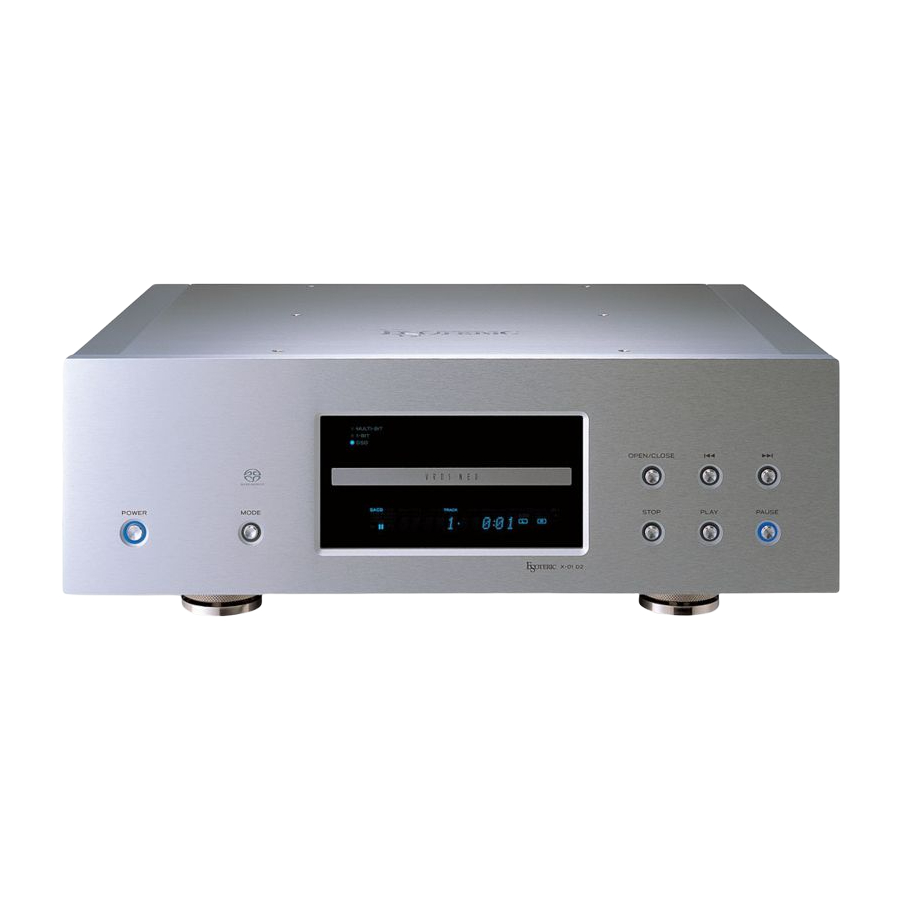
X X - - 0 0 1 1
SUPER AUDIO CD PLAYER
CONTENTS
PC boards shown are viewed from parts side.
●
The parts with no reference number or no parts number in the
●
exploded views are not supplied.
As regards the resistors and capacitors, refer to the circuit diagrams
●
contained in this manual.
Parts marked with this sign are safety critical components. They
£
●
must be replaced with identical components - refer to the appropriate
parts list and ensure exact replacement.
For U.S.A.
・ ・ ・ ・ ・ ・ ・ ・ ・ ・ ・ ・ ・ ・ ・ ・ ・ ・ ・ ・ ・ ・ ・ ・ ・ ・ ・ ・ ・ ・ ・ ・ ・ ・ ・ ・ ・ ・
・ ・ ・ ・ ・ ・ ・ ・ ・ ・ ・ ・ ・ ・ ・ ・ ・ ・ ・ ・ ・ ・ ・ ・ ・ ・ ・ ・ ・ ・ ・ ・ ・ ・ ・ ・ ・ ・ ・ ・ ・
・ ・ ・ ・ ・ ・ ・ ・ ・ ・ ・ ・ ・ ・ ・ ・ ・
・ ・ ・ ・ ・ ・ ・ ・ ・ ・ ・ ・ ・ ・ ・ ・ ・ ・ ・ ・ ・ ・
・ ・ ・ ・ ・ ・ ・ ・ ・ ・ ・ ・ ・ ・ ・ ・ ・ ・ ・ ・ ・ ・ ・ ・ ・ ・ ・
NOTES
2
3
4
10
22
S-0128A
Advertisement

Related Manuals for Esoteric X-01


Summary of Contents for Esoteric X-01
-
Page 1: Table Of Contents
SERVICE MANUAL X X - - 0 0 1 1 SUPER AUDIO CD PLAYER For U.S.A. CONTENTS 1 SPECIFICATIONS ・ ・ ・ ・ ・ ・ ・ ・ ・ ・ ・ ・ ・ ・ ・ ・ ・ ・ ・ ・ ・ ・ ・ ・ ・ ・ ・ ・ ・ ・ ・ ・ ・ ・ ・ ・ ・ ・ 2 ADJUSTMENTS ・... -
Page 2: Specifications
1 SPECIFICATIONS General Accessories System ..............SACD and CD Power cord x 1 Power supply ............AC 120 V, 60 Hz Remote Control Unit (RC-941) x 1 Power consumption ..............40 W Batteries (AA, R6, SUM-3) x 2 Screwdriver x 1 Weight..............25 kg (55-1/16 lb) Felt x 3 External dimensions (W x H x D) ....442 x 153 x 353 mm Warranty card x 1... -
Page 3: Adjustments
2 ADJUSTMENTS 2-1 Sled Offset Adjustment 1. Connect the probe of oscilloscope to pin 1 (SLCNT) of P205 on CORE PCB, and the probe earth to pin 2 (SL18V). 2. Set the oscilloscope's voltage range to DC100mV, and the time calibration to 10mS. -
Page 4: Exploded Views And Parts List
3 EXPLODED VIEWS AND PARTS LIST EXPLODED VIEW-1 ¡ ∞ ¡ º ∞ ª • ™ ¡ œ ∞ † ∞ ∞ • ∞ £ £ ¨ • £ £ ™ ˆ ¢ ∞ ¢ £ £ ™ ¥ ™ £... - Page 5 EXPLODED VIEW-1 REF.NO. PARTS NO. DESCRIPTION REMARKS 1‑ 1 M01724000A TOP PANEL,X‑01 1‑ 2 M01777500A CUSHION,FOAM TOP 1‑ 3 M01766810A FRAME,TOP R EXP 1‑ 4 M01766710A FRAME,TOP L EXP 1‑ 5 M01648100B SIDE PANEL,L 1‑ 6 M00387502A COLLAR,SCREW(N01SP) 1‑ 7 E95182300A PCB ASSY,POWER 1‑ 8 M01724500A PLATE,PCB PWR 1‑ 9 M01766900A BRACKET,MECHA 1‑10 M01839400A POLYEST SH,MECHA T0.25 1‑11 M01839500A POLYEST SH,MECHA T0.35 1‑12 M01782900A RUBBER SH,BRACKET 1‑13...
- Page 6 EXPLODED VIEW-1 REF.NO. PARTS NO. DESCRIPTION REMARKS 1‑63 M01495001A STAND,FOOT 13 1‑64 M01494901A FOOT(B) 11 1‑65 M01839300B SPACER,ZNC M4X4 1‑66 E95181200A PCB ASSY,DAC 2CH A‑R 1‑67 M01939700A GASKET,E02F4T/3X310 1‑68 M01571300A SHEET,SHIELD(CU)‑10 1‑69 E0096620 CORE,E04SR130525AB BLACK 1‑70 M01939800A GASKET,E02F4T/5X420 1‑71 M01937300A SHRINK SHIELD,20X180 1‑72 E0096950 CORE,E04FG221308 1‑73 E0081410 CORE,E04RC281613 1‑74 M01939600A GASKET,E02S080030ET/50MM 1‑75...
- Page 7 EXPLODED VIEW-2 CAUTION Avoid disassembling MECH UNIT without clear intention (See page 9)! HOUSING ASSY,MOTOR BASE ASSY,PU & −7−...
- Page 8 EXPLODED VIEW-2 REF.NO. PARTS NO. DESCRIPTION REMARKS 2‑ 1 M01717900A MAGNET,CLAMPER 2‑ 2 M01717800A CLAMPER,DISC 2‑ 3 M01716900A HOLDER,CLAMPER 2‑ 4 M01716800A PLATE,CLAMPER 2‑ 5 5800979500 LOADING BELT 2‑ 6 M01771500A WASHER,3.6X7.2X0.5T CUT 2‑ 7 M01711300A GEAR(B) 2‑ 8 M00350500A GEAR(A) 2‑ 9 5300060100 SW,PUSH SPPB12 2‑10 M0181760 CABLE CLAMP,TIEMOUNT MB1 2‑11 E0038180 SW,1‑2 N SSCF21R‑1 2‑12 E00859900A FLAT CABLE,FFC SW 2‑13...
- Page 9 EXPLODED VIEW-2 REF.NO. PARTS NO. DESCRIPTION REMARKS 2‑56 5785304100 WASHER,POLY 4.1X6.5X0.25T 2‑57 M0187931 CABLE CLAMP,NYLON AB‑5N 2‑61 B00145800A SCREW,JHA 4X20FZC 2‑62 B00053800A SCREW,MPAR 2X3FNI 2‑63 B0006360 SCREW,MPPR 1.7X5.0 2‑64 5780102008 SCREW,PAN M2X8 2‑65 5780013006 SCREW,BPA 3X6FNI 2‑66 5780102604 SCREW,PAN M2.6X4 2‑67 5780002603 SCREW,BPA 2.6X3FZC 2‑68 5780103004 SCREW,PAN M3X4 2‑69 5780102606 SCREW,PAN M2.6X6 2‑70 5780103003 SCREW,PAN M3X3 2‑71...
-
Page 10: Pc Boards And Parts List
4 PC BOARDS AND PARTS LIST CORE PCB (SIDE A) This PCB is a six-layered board. −10−... - Page 11 CORE PCB (SIDE B) This PCB is a six-layered board. −11−...
- Page 12 DAC 2CH PCB This PCB is a four-layered board. −12−...
- Page 13 DAC 4CH PCB This PCB is a four-layered board. SW-JOINT PCB PHOTO INT PCB C-MOTOR PCB T-MOTOR PCB −13−...
- Page 14 FRONT PCB D-OUT PCB PWRLED PCB −14−...
- Page 15 POWER PCB REG PCB PSW PCB INLET PCB −15−...
- Page 16 CORE PCB ASSY CORE PCB ASSY REF.NO. PARTS NO. DESCRIPTION REF.NO. PARTS NO. DESCRIPTION E00922700A PCB ASSY,CORE A‑ID RA503,RA504 R0066824 R,ARRAY 1/16W 4X100 J E90180300C PCB,CORE RA601‑RA607 R0066744 R,ARRAY 1/16W 4X47 J C511 C0034544 CS, 16V 1.0UF M TCFG RA608,RA609 R0066624 R,ARRAY 1/16W 4X15 J C518 C0034544 CS, 16V 1.0UF M TCFG RA701‑RA709 R0066624 R,ARRAY 1/16W 4X15 J C524 C0034544 CS, 16V 1.0UF M TCFG RA710 R0066744 R,ARRAY 1/16W 4X47 J C802 C0036264 CE, 10V 47UF M SVP...
- Page 17 CORE PCB ASSY DAC 2CH A-L PCB ASSY REF.NO. PARTS NO. DESCRIPTION REF.NO. PARTS NO. DESCRIPTION U811 S0053183 IC,SM5819AF D1101,D1102 5224016420 DIODE,S5688G U812 S00538500B IC,AUDIO SEL X‑01 V1.01 D1301‑D1304 S0037480 DIODE,21DQ04 X201 E0085574 RESONATOR,CSTCR4M00G53‑R0 J1101 E00353701A JACK,RCA 1P WHITE NICKING X801 E0070544 RESONATOR,LIM55A‑T27.0MHZ J1102 5334078800 CONNECTOR,XLM‑3‑32PCV X802 E0086434 RESONATOR,LIM55A‑T12.288M K1101,K1102 5290015600...
- Page 18 DAC 2CH A-L PCB ASSY DAC 2CH A-R PCB ASSY REF.NO. PARTS NO. DESCRIPTION REF.NO. PARTS NO. DESCRIPTION U1306 £ 13447956 IC,NJM7812FA Q1201,Q1202 5232255620 TR,DTC114ESA U1307 £ 13447973 IC,NJM7912FA R1103 R0108611 RN,1/4W 750 OHM F U1501 S0053114 IC,TC7SET08F R1106‑R1108 R0108801 RN,1/4W 4.7KOHM F U1502 S0051934 IC,TC74VHC163FT R1203 R0108611 RN,1/4W 750 OHM F U1503 S0051954 IC,TC74VHC153FT...
- Page 19 DAC 4CH A PCB ASSY PHOTO INT PCB ASSY Part of GATHER MECHA PCB ASSY REF.NO. PARTS NO. DESCRIPTION REF.NO. PARTS NO. DESCRIPTION C2406,C2411 C0007510 CE, 16V 47UF M SA E95180800A PCB ASSY,PHOTO INT C2407‑C2409 C0042652 CE, 16V 100UF M LXZ E90180800A PCB,PHOTO INT C2413,C2415 C0035340 CE, 16V 100UF M SA P196 13124436 CONNECTOR,ZH S 3B‑ZR C2418,C2420 5260473420 CE, 25V 100UF M PZ U191 5228017700 PHOTO‑INTERRUPTTER,GP2S24...
- Page 20 FRONT PCB ASSY POWER PCB ASSY Part of GATHER A PCB ASSY Part of GATHER B PCB ASSY REF.NO. PARTS NO. DESCRIPTION REF.NO. PARTS NO. DESCRIPTION S0018723 IC,M66004FP C23 £ C0040902 CQ,100V 0.22UF J S0053230 IC,RPM7238‑H9 C24 £ 5260463420 CE, 50V 100UF M AU U6 £ S0051390 IC,NJU7223F33 C25‑C27 £ 5260462920 CE, 50V 47UF M AU S0047794 IC,TC74VHCT08AF 5260463220...
- Page 21 REG PCB ASSY Part of GATHER B PCB ASSY REF.NO. PARTS NO. DESCRIPTION E95182400A PCB ASSY,REG E90182400A PCB,REG C13,C15 £ 5263167923 C,METAL 0.10UF 50V J 5336303800 CONN PLUG,B8B‑EH(WHT) U01 £ 5220451400 IC,PQ05RF11 U03 £ S0048710 IC,PQ30RV2 PSW PCB ASSY Part of GATHER B PCB ASSY REF.NO. PARTS NO. DESCRIPTION E95182500A PCB ASSY,PSW E90182500A PCB,PSW...
-
Page 22: Included Accessories
5 INCLUDED ACCESSORIES INCLUDED ACCESSORIES REF.NO. PARTS NO. DESCRIPTION REMARKS D00816700A OWNER'S MANUAL,E/F/G D00838300A BINDER,MANUAL ESOTERIC E00857900A REMOTE CONTROL UNIT,RC‑941 5347007000 BATTERY,UM‑3 £ E0093270 POWER CORD,3P M01499300A CUSHION,FOOT 40 J0079750 SCREW DRIVER,NDV‑5+ −22−... - Page 23 X-01 WIRING DIAGRAM PCBA,INLET P1003 PCBA,D-OUT P1004 PCBA,REG P1501 P602 P1303 P1306 P1303 P1306 P2503 TRANS,DIGITAL P1302 P1305 P1302 P1305 P2502 P401 P1301 P1304 P1301 P1304 P2501 PCBA, PCBA,DAC4CH DAC2CH R PCBA,POWER PCBA, DAC2CH L P1004 P1004 P2001 P803 TRANS,ANALOG...
- Page 24 X-01 WIRING DIAGRAM POWER SUPPLY PCBA,INLET PCBA,REG B2P3-VH B14B-EH B8B-EH P15 B4B-EH-RED VIN1 VOUT1 P14 B4B-EH VIN2 VOUT2 TRANS,DIGITAL P07 B7B-PH S7B-PH-SM3 P401 FGND FGND P12V P12V PCBA,CORE PGND PGND BGND BGND PCBA,POWER P08 B7B-PH-YEL TRANS,ANALOG GND1 /RESET /P_DOWN FL_AC2...
- Page 25 X-01 WIRING DIAGRAM DATA SIGNAL P1004 P1501 PCBA,D-OUT WORD_IN DGND P2001 P1003 B2B-PH-RED 768Fs2 768Fs2 B2B-PH-RED SDO WCK SDO WCK SDO BCK SDO BCK SDO SL/SR SDO SL/SR FFC_15P PCBA,DAC 4CH SDO C/SW SDO C/SW P1003 B4B-PH Fs SEL1 Fs SEL1...
- Page 26 X-01 WIRING DIAGRAM MECHA SECTION 00_6232_109_103_800 P201 SLA3 SLA2 SLA1 SLED FFC_9P MOTOR PCBA,CORE P203 P204 P202 S3B-PH-SM3 00_6232_115_103_800 P101 S12B-ZR-SM3A 00_6200_237_032_800 FFC_23P FFC_15P S12B-ZR-SM3A P103 P104 S3B-PH-SM3 PICKUP UNIT PCBA,SPDL 15FMN-STK P151 P171 P160 TRY+ T-MOTOR P152 MOTOR3 P172...
- Page 27 X-01 SCHEMATIC DIAGRAM CORE PCB (1/8) (RF AMP), SW-JOINT PCB, C-MOTOR PCB, T-MOTOR PCB, PHOTO INT PCB T135 CD/XDVD T141 RFAC CD/XDVD CD/XDVD T140 RFAC RFOP T136 C113 4700p T142 R102 T137 Q101 2SK3019 C114 4700p FA5V T143 C115 C146 FAGND 0.1u...
- Page 28 X-01 SCHEMATIC DIAGRAM CORE PCB (2/8) (DRIVER) FD3.3V MECH_U-COM TRYCTL TRYCTL R266 FP8V T209 T210 T211 T212 T213 R267 TROD TRCD XFTSMUTE TSD-M FD8V S201 SKQGAB C243 LMT_SW P207 0.1u FPGND B9B-ZR-SM3 FO/TR/LOAD TSD-M S202 SKQGAB /MUTE XFTSMUTE TRYFG P-INT...
- Page 29 X-01 SCHEMATIC DIAGRAM CORE PCB (3/8) (DVD DECODER) FD3.3V T388 AMPSEN C347 0.1u AMPSDT RA324 TO_MPEG AMPSCK RAC1608-1014DJT DFCT MIRR SPDIFB U305 RFAC CDDA_LRCK T309 T310 TC74LVX244FT CDDA_BCK C2PO CDDA_DATA DRVCLK DRVCLK LRCK LRCK SCLK1 DRVRX R313 R314 DRVRX TXD1...
- Page 30 X-01 SCHEMATIC DIAGRAM CORE PCB (4/8) (POWER) L401 T408 4.7uH/LQH55DN FA5V FA5V FA5V L402 T409 4.7uH/LQH55DN FP5V FP5V FP5V D401 1SS355 L404 T410 U401 BA033FP 4.7uH/LQH32CN FA3.3V FA3.3V FA3.3V T401 T403 T405 T407 PGND BGND T402 T404 T406 C405 FGND...
- Page 31 X-01 SCHEMATIC DIAGRAM CORE PCB (5/8) (DSD DECODER) FD3.3V FA5V C537 RA501 RA502 R506 2.2K RAC1608-1034DJT RAC1608-1034DJT T548 C538 WARF 22u/16V U503A FROM_RF-AMP T547 AD8062 C539 FD3.3V RFAC2 0.1u R503 FAGND C551 0.1u RFAC C535 0.01u RFAC R504 U505 RA503...
- Page 32 X-01 SCHEMATIC DIAGRAM CORE PCB (6/8) (MPEG DECODER) BD1.8V L601 BLM18PG300SN1 C601 C602 C603 C604 C605 C606 C607 C608 C609 C610 C611 C612 C613 2.2u(2125) 47u/16V 0.1u 0.1u 0.1u 0.1u 0.1u 0.1u 0.1u 0.1u 0.1u 0.1u 0.1u SVA_INT3 MC_INT2 MC_INTR...
- Page 33 X-01 SCHEMATIC DIAGRAM CORE PCB (7/8) (B/E U-COM) RA705 MCA[10..30] TO_MPEG MCA[10..30] BD2.5V RAC1608-1504DJT MCD[0..15] L701 MCA11 RA701 MCD[0..15] BLM18PG300SN1 MCA12 RAC1608-1504DJT MCA13 MCD0 MCA14 MCA14 MCD1 U702 M5M29GT16-BVP-80 MCD2 (SOCKET:IC197-4807-20XX) C701 C702 C703 C704 C705 C706 RA706 MCD3 BD3.3V 2.2u(2125)
- Page 34 X-01 SCHEMATIC DIAGRAM CORE PCB (8/8) (AUDIO DSP) BD3.3V2 R828 MC3.3V 27MHz 6,7,8 27MHz U807 U803 L801 TC7SH08FU M5M54R08ATP-10 BLM18PG300SN1 C849 R801 C845 T802 0.1u 0.1u C863 C801 C802 T801 SMA0 47u/16V 2.2u(2125) 47u/16V C803 0.1u U802 BU2288FV SMA1 SMA18...
- Page 35 X-01 SCHEMATIC DIAGRAM DAC 2CH L PCB (1/2) P1005 C1015 +3.3VC +12VA +12VA MUTE LR +3.3VC DSD_EN C1009 C1016 +3.3VC U1004 K1102 D1102 R1117 BU2288FV 47U/6.3V POSCAP PH-3 RELAY S5688G U1005 TC74VHC157FT GNDD TP1020 GNDD VDD2 W1107 JUMPER R1122 VSS2...
- Page 36 X-01 SCHEMATIC DIAGRAM DAC 2CH L PCB (2/2) U1511A TC74VHC86FT +3.3VG 27M OUT1 R1520 C1531 R1521 GND G U1511B TC74VHC86FT C1532 47U/6.3V POSCAP U1511D P1503 TC74VHC86FT 27M OUT2 27M OUT2 R1522 R1523 PH-2P +3.3V VC C1517 GND G U1511C R1514...
- Page 37 X-01 SCHEMATIC DIAGRAM DAC 2CH R PCB C1101 C1110 C1125 C1130 C1102 C1111 47/16V OS U1101 47/16V OS PCM1704U -5VA W1005 -5VDA C1126 C1131 R1102 100/16V OS R1105 100/25V PZ DATA -VCC R1041 2.2(10mm) 2.2(10mm) BCLK REF DC C1109 100/16V LXZ...
- Page 38 X-01 SCHEMATIC DIAGRAM DAC 4CH PCB +12VA P2001 P2002 768Fs 768Fs +5VD W2011 JUMPER DOL1 PCM LRCK PCM LRCK C2101 C2110 C2116 K2101 D2101 DOR1 PCM BCK PCM BCK 100P R2108 RELAY S5688G W2012 R2102 C2114 4.7K(10mm) R2105 C2119 PCM SL/SR...
- Page 39 X-01 SCHEMATIC DIAGRAM D-OUT PCB C2003 1/50V 1/50V U2001 uPD4721 C2006 P2001 +3.3V C2004 1/50V J2001 R2001 1/50V C2007 232C-DT C2001 C2002 MC-DT 100/25V STBY# C2005 R2007 RS-232C VCHA R2002 1/50V 232C-RQ DIN1 DOUT1 R2006 L2004 MC-RQ DIN2 DOUT2 R2005...
- Page 40 X-01 SCHEMATIC DIAGRAM FRONT PCB, PWRLED PCB TO CORE P701 TO VIDEO J301 TO AUDIO TO AUDIO B8B-PH B10B-PH B9B-PH 10FLT-SM1-TB B3B-PH U3-14 U3-7 FROM FRONT P7 B3B-PH SOLDER SIDE MOUNT DTC114ESA SLR343BCT FL_DATA_5 IF_DATA 74VHCT04 74VHCT04 FL_SCK_5 IF_SCK SLR343BCT...
- Page 41 X-01 SCHEMATIC DIAGRAM POWER PCB, INLET PCB, PSW PCB, REG PCB B2B-PH (N.M) REAR CHASISS GND CHASISS GND CHASISS GND FRONT T2A L 250V SLOW BLOW T4A L 125V SLOW BLOW C08-C12 is P-7.5 F-18 C35-C42 is P-7.5 F-18 H-35.5 Limit H-35.5 Limit...
Need help?
Do you have a question about the X-01 and is the answer not in the manual?
Questions and answers