AgileX BUNKER User Manual
Hide thumbs
Also See for BUNKER:
- User manual (17 pages) ,
- User manual (23 pages) ,
- User manual (35 pages)
Table of Contents
Advertisement
Quick Links
Advertisement
Table of Contents

Related Manuals for AgileX BUNKER


Summary of Contents for AgileX BUNKER
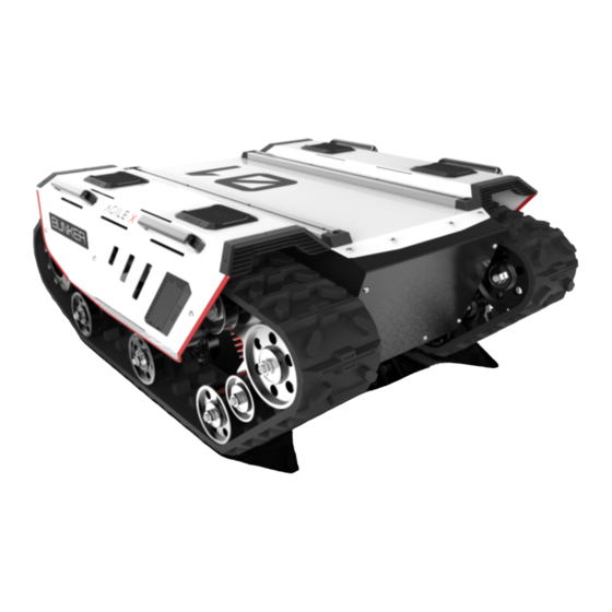
- Page 1 BUNKER AgileX Robotics Team User Manual 2020.03 V.2.1.0...
- Page 2 If you have any questions about use, please contact us at support@agilex.ai. Please follow and implement all assembly instructions and guidelines in the chapters of this manual, which is very important. Particular...
- Page 3 The design and use of the complete system need to comply with the safety requirements established in the standards and regulations of the country where the robot is installed. BUNKER integrators and end customers have the responsibility to ensure compliance with the applicable laws and regulations of relevant countries, and to ensure that there are no major dangers in the complete robot application.
-
Page 4: Table Of Contents
CONTENTS 1 Bunker Introduction 3.4 Firmware upgrades 1.1 Component list 3.5 BUNKER ROS Package use 1.2 Tech specifications example 1.3 Required for development 4 Attention 2 The Basics 4.1 Battery 2.1 Description of electrical 4.2 Operational environment interface 4.3 Electrical /extension cords 2.2 Instruction on remote control... -
Page 5: Bunker Introduction
1.3 Required for development FS RC transmitter is provided (optional) in the factory setting of BUNKER, which allows users to control the chassis of robot to move and turn; CAN and RS232 interfaces on BUNKER can be used for user’ s customization. -
Page 6: The Basics
2 The Basics This section provides a brief introduction to the BUNKER mobile robot platform. It is convenient for users and developers to have a basic understanding of BUNKER chassis. 2.1 Description of electrical interface The interface at rear end is shown in Figure 2-1, where Q1 is CAN and 48V power supply aviation interface; Q2 is the power switch;... -
Page 7: Instruction On Control Demands And Movements
Coordinate System for Vehicle Body As shown in Figure 2.4, the vehicle body of BUNKER is in parallel with X axis of the established reference coordinate system. In RC control mode, push the remote control stick S1 forward to move in the positive X direction, push stick S1 backward to move in the negative X direction. -
Page 8: Charging
BUNKER is equipped with a standard charger by default to meet customers' recharging demand. The detailed operating procedure of charging is shown as follows: Make sure the electricity of BUNKER chassis is powered off. Before charging, please make sure Q2 (key switch) in the rear control console is turned off;... - Page 9 Table 3.2 Description of Failure Information Description of Failure Information Byte Meaning bit [0] Low-voltage failure bit [1] Low-voltage warning bit [2] Remote control signal lost protection(0: Normal 1: Lost signal) bit [3] Drive 1 communication failure(0: Normal 1: Failure) byte [5] bit [4] Drive 2 communication failure(0: Normal 1: Failure)
- Page 10 Note[1] Description for control mode When the remote control is power off, the control mode of BUNKER is can command control by default , that means chassis can be controlled by commands directly. Please note that the control mode in command still need to set 0x01 if the speed command need to be executed successfully.
- Page 11 Note[2]Testing data : The following data is used for testing only. 1.The chassis moves forward at 0.15m/s. byte [0] byte [1] byte [2] byte [3] byte [4] byte [5] byte [6] byte [7] 0x01 0x96 0x00 0x00 0x00 0x00 0x00 0x00 2.The chassis rotates at 0.2rad/s.
- Page 12 Table 3.9 Drive Status Byte Byte Description bit [0] Low-voltage (0: Normal 1: Low) bit [1] Motor over- temperature (0: Normal 1: Over-temperature) bit [2] Reserved bit [3] Reserved byte [5] bit [4] Reserved bit [5] Reserved bit [6] Reserved bit [7] Reserved Table 3.10 Odometer Feedback Frame...
-
Page 13: Can Cable Connection
3.3.3Implementation of CAN Red:VCC(battery positive) Black:GND(battery negative) Correctly start the chassis of BUNKER mobile robot, and turn on FS RC Blue:CAN_L transmitter. Then, switch to the command control mode, i.e. toggling SWB mode of FS RC transmitter to the top. At this point, BUNKER... -
Page 14: Bunker Ros Package Use
AGILEX BUNKER top aviation power socket ×1 Hardware connection and preparation Lead out the CAN wire of the BUNKER top aviation plug or the tail plug, and connect CAN_H and CAN_L in the CAN wire to the CAN_TO_USB adapter respectively;... -
Page 15: Attention
A:Normally, if BUNKER can be controlled by a RC transmitter, it means the chassis movement is under proper control; if the chassis feedback frame can be accepted, it means CAN extension link is in normal condition. Please check the CAN control frame sent to see whether the data check is correct and whether the control mode is in command control mode. -
Page 16: Product Dimensions
6 Product Dimensions 6.1 Product outline dimension illustration... -
Page 17: Top Expansion Stent Size
6.2 Top expansion stent size description diagram... - Page 18 AgileX Robotics CO., Ltd WWW.AGILEX.AI Email: sales@agilex.ai TEL:+86-769-22892150...
Need help?
Do you have a question about the BUNKER and is the answer not in the manual?
Questions and answers