
Subscribe to Our Youtube Channel
Related Manuals for AMOT G Series


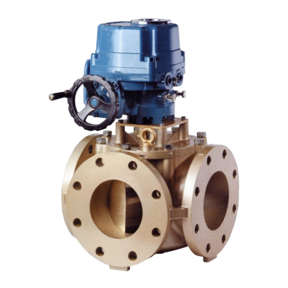
Summary of Contents for AMOT G Series
- Page 1 G-Valve (electric actuator) Operation and Maintenance Manual Doc No: OMMG00012 Revision: 12 – NOV 2019...
-
Page 3: Table Of Contents
Contents Introduction ...................... 5 Scope ................5 Safety ................6 Maintenance ............... 6 Product Support ..............6 Typographical Conventions ........... 6 European Union Directives ............ 7 System Overview ..................... 9 Description ................. 9 Identification of Model Number ..........11 Modes of Operation ............12 Conversion between Modes of Operation ...... - Page 4 Contents Technical Data ....................73 Selection of G-Valve options ..........73 Technical Specifications ............78 Rev 12 – NOV 2019 OMMG00012...
-
Page 5: Introduction
EU EMC Directive .............. 7 1.6.4 EU Pressure Equipment Directive ........7 Scope This Manual details the installation, operation and maintenance of the AMOT electrically actuated G-Valve system. Each item of equipment is described in a separate section as follows: Section 4 Actuator &... -
Page 6: Safety
Introduction Safety Certain operations within this manual are potentially hazardous and could cause injury to personnel or damage to equipment if the instructions are not carried exactly as described. Where a significant, potential hazard exists, the following text appears immediately before steps in the procedure that present a particular hazard: WARNING A Warning identifies a hazard that could cause injury to personnel. -
Page 7: European Union Directives
European Union Directives 1.6.1 EU Machinery Directive The AMOT Model G Valve, as a component, is not considered to be a machine. To fully comply with the Directive however, the machine into which the valve is installed must comply with the requirements of the machinery directive before the valve is put into operation. - Page 8 6GEF 8GEF PN10 10GEF 12GEF (SEP) 14GEF PN16 16GEF 150lb Users who are uncertain as to the applicability of the Directive should contact AMOT before installation, particularly if using more hazardous (Group 1) fluids. Rev 12 – NOV 2019 OMMG00012...
-
Page 9: System Overview
System Overview Section 2 System Overview Contents Para Page Description ................. 9 2.1.1 Features ................9 2.1.2 Typical Applications ............10 Identification of Model Number ............ 11 Modes of Operation ..............12 Conversion between Modes of Operation ........12 System Components ..............13 Description The G Valve and its supporting equipment are designed for the control of fluid temperature by ‘diverting’... -
Page 10: Typical Applications
System Overview 2.1.2 Typical Applications Lubricating Oil Temperature Control Lubrication oil temperature control is normally configured in a mixing application controlling the return temperature to the heat load. The temperature is normally measured as close as possible to the sump return. -
Page 11: Identification Of Model Number
System Overview Identification of Model Number Size 2 inch (DN50) 3 inch (DN80) 4 inch (DN100) 6 inch (DN150) 8 inch (DN200) 10 inch (DN250) 12 inch (DN300) 14 inch (DN350) 16 inch (DN400) Type Electric actuation Materials Bronze Cast Iron Ductile Iron Steel Stainless Steel... -
Page 12: Modes Of Operation
System Overview Modes of Operation Fig 1 Modes of Operation Conversion between Modes of Operation The mode of operation is defined in the model code section “Rotor Type” on the previous page. It is possible to change the mode of operation in some circumstances, as follows: Table 2 Mode Conversion –... -
Page 13: System Components
System Overview 1 = Requires a different rotor. See section 3.4, page 16. 2 = Rotor needs to be turned with respect to the actuator. See section 3.4, page 16. 3 = Direction of operation needs to be changed with a Configurator if a Positioner is fitted, or connections to terminals 11 and 12 swapped for switched live versions. - Page 14 System Overview Rev 12 – NOV 2019 OMMG00012...
-
Page 15: Valve Body
Valve Body Section 3 Valve Body Contents Para Page Description ................15 Installation ................15 Operation ................. 16 Maintenance ................16 3.4.1 Dismantle and Assemble 2 and 3 inch Valves ..... 16 3.4.2 Dismantle and Assemble 4, 6 and 8 inch Valves....17 3.4.3 Dismantle and Assemble 10 and 12 inch Valves .... -
Page 16: Operation
Valve Body Operation CAUTION Damage can be caused to the valve assembly if a cheater or extension bar is used on the handwheel. Do not use any mechanical aid to turn the handwheel. Under normal conditions, the valve is operated electrically by the actuator. Manual operation is possible at any time by disengaging electrical drive with the actuator declutching lever and turning the handwheel. -
Page 17: Dismantle And Assemble 4, 6 And 8 Inch Valves
Valve Body Switch off and isolate power to the actuator. Using the handwheel, turn the valve to the low temperature position. Mark adjacent points on the actuator and coupling and also on the coupling and cover (5) to aid reassembly. WARNING If an actuator is removed from a valve fitted in a live system, the valve rotor may rotate uncontrollably in the body. - Page 18 Valve Body Using the handwheel, turn the valve to the low temperature position. Mark adjacent points on the actuator and coupling and also on the coupling, retaining plate (5) and cover (7) to aid reassembly. WARNING If an actuator is removed from a valve fitted in a live system, the valve rotor may rotate uncontrollably in the body.
-
Page 19: Dismantle And Assemble 10 And 12 Inch Valves
Valve Body Remove and discard the upper and lower shaft O rings (9 & 11). Inspect the valve internals for wear, damage and cleanliness. Clean and replace if necessary. Note It is recommended that the upper and lower composite bearings (6 & 10) are replaced at this stage. - Page 20 Valve Body Fig 5 10 and 12 inch Valves Taking care that the rotor is not lifted with the cover, carefully lift off the cover (6). Remove and discard the cover O ring (7). Remove the rotor assembly from the valve body. Remove and discard the upper and lower shaft O rings (10).
-
Page 21: Recommended Spares
Valve Body Carefully insert the rotor assembly into the valve body with the rotor in the low temperature position. Fit a new cover O ring (7) to the cover (6) and position the cover on the valve, aligning the marks made during disassembly. Fit the cover bolts (1) and washers and tighten to a torque of 244 Nm. - Page 22 Valve Body Composite Bearing, 46457L016 (1) 46457L025 (1) 46457L025 (1) Upper 46457L120 (1) 46457L120 (1) Coupling Pin 43419L022 (1) 43406L035 (1) 43406L035 (1) 10 and 12 inch Valves (Fig 5, page 20) Service Kit Part No. 47961X110 • (10 inch valve) Service Kit Part No.
-
Page 23: Electric Actuator
Electric Actuator Section 4 Electric Actuator Contents Para Page Description ................23 4.1.1 Mechanical ..............23 4.1.2 Electrical ............... 24 4.1.3 Versions ................ 24 4.1.4 Optional Positioner ............24 4.1.5 Actuator Internal Wiring ..........25 Identification of Model Number ............ 29 Mechanical Installation ............... -
Page 24: Electrical
Electric Actuator preventing fluid forces in the valve from reverse – driving the actuator. Manual override is fitted as standard, enabling valve operation without electrical power. The manual override is automatically disengaged when electrical power is re-applied, preventing risk of injury from the handwheel. 4.1.2 Electrical The actuator contains the following electrical equipment: Electric motor with integral bi-metallic cut-outs which disconnect the... -
Page 25: Actuator Internal Wiring
Electric Actuator Electric Actuator Positioner Fig 6 External Positioner The Positioner is a versatile, micro-processor controlled unit which is fully configurable for various control functions. The configuration of the unit is detailed in section 4.6. The main features of the Positioner are: Control of the actuator by an externally generated 4 –... - Page 26 Electric Actuator Fig 7 EA Actuator Internal Wiring – Without Positioner Rev 12 – NOV 2019 OMMG00012...
- Page 27 Electric Actuator Fig 8 EA Actuator Internal Wiring – With Positioner for Switched Live Control OMMG00012 Rev 12 – NOV 2019...
- Page 28 Electric Actuator Fig 9 EA Actuator Internal Wiring – With Positioner Rev 12 – NOV 2019 OMMG00012...
-
Page 29: Identification Of Model Number
Electric Actuator Identification of Model Number Size/Nominal Torque 100 Nm 200 Nm Shaft Connection 17 mm square (EA 100 only) 22 mm square (EA 200 only) Supply Voltage 110 V ac 220 V ac Features Standard (1 kΩ potentiometer) Standard (5 kΩ potentiometer) Standard with positioner port Direct Mode (Clockwise rotation with increasing demand current) -
Page 30: Actuator Re-Orientation
Electric Actuator WARNING The actuator is heavy (EA100 – 16.6 kg and EA200 – 22 kg). The appropriate manual handling precautions must be applied to prevent personnel injury. Mount the actuator onto the valve body in accordance with Sect 4.8.1 (page 36). - Page 31 Electric Actuator 1. Ensure that there is no flow through the valve before proceeding. 2. Switch off power to the actuator. 3. Use the lever and handwheel to rotate the valve to one end of stroke. It does not matter which end. 4.
-
Page 32: Electrical Installation
Electric Actuator Electrical Installation The following precautions and limitations must be observed before electrical connection of the actuator. CAUTION Electrical power must not be supplied to both the open and close motor windings at the same time or overheating will occur. When power is applied to either the open or close windings, the other must be isolated. -
Page 33: Electrical Position Feedback
Electric Actuator Fig 11 Actuator Internal Cable Routing Electrically connect the actuator in accordance with the system wiring diagrams in Section 7 (System Integration). Schedule a periodic maintenance check to ensure proper performance and long service life. It is recommended that the actuator is checked for correct operation at least once per month. -
Page 34: Positioner Configuration And Calibration
Electric Actuator Positioner Configuration and Calibration The Positioner is provided fully calibrated and configured according to the model code of the valve that the actuator is fitted to. Changes can be made if required by means of a Configurator box connected between the positioner and the actuator to access calibration and configuration options. -
Page 35: Operation
Electric Actuator Operation CAUTION Damage can be caused to the valve assembly if a cheater or extension bar is used on the handwheel. Do not use any lever / mechanical aid to turn the handwheel. The actuator operates as soon as electrical power is applied. Versions with a Positioner can be controlled by an 8071D PID controller based system or an externally generated 4 –... -
Page 36: Removal And Installation Onto Valve Body
Electric Actuator 4.8.1 Removal and Installation onto Valve Body The size of bolts and associated torque setting is dependent on the size of the valve. Throughout the removal and installation procedure, refer to Table 3 and Fig 12 (page 37) for the relevant bolt sizes and torque settings: Table 3 Actuator mounting bolt size and torque settings Valve Size Mounting Plate to... - Page 37 Electric Actuator Fig 12 Actuator mounting Removal WARNINGS Lethal voltages are present in the actuator presenting a shock hazard to personnel. Ensure the power supply to the actuator is isolated before the cover is removed. If an actuator is removed from a valve fitted in a live system, the valve rotor may rotate uncontrollably in the body.
-
Page 38: Lubrication
Electric Actuator Remove the four bolts and spring washers (Fig 12 items 1 and 2) securing the actuator mounting plate to the valve. WARNING The actuator is heavy (EA100 – 16.6 kg and EA200 – 22 kg). The appropriate manual handling precautions must be applied to prevent personnel injury. -
Page 39: Limit Switch Replacement
Electric Actuator 4.8.3 Limit Switch Replacement CAUTION During replacement of the limit switches, the actuator must be manually positioned. If the actuator is mounted on a valve which is installed in the pipework, it will affect the process flow of the system. Replace the limit switches as follows (refer to Fig 13, page 40) WARNING Lethal voltages are exposed when the actuator cover is removed,... - Page 40 Electric Actuator Fig 13 Limit Switch assembly Disconnect the limit switch pair wires from the terminal strip (the switches identified as item 25 are the open switches and item 26 are the close switches). Remove the two screws (28), nuts (19) and washers (20) and remove the switch pair to be replaced.
-
Page 41: Limit Switch Adjustment - Rotor Not Visible
Electric Actuator Connect the replacement limit switch pair wires to the terminal strip. Slide the cams and cam spacer (12) onto the position indicator shaft. Whilst viewing the actuator as illustrated, ensure the cam grubscrews are facing you when the flats face the switches. Position the upper limit switch bracket (9) and slide down the shaft with the cams. - Page 42 Electric Actuator Switch off and isolate the actuator electrical power supply. Remove the socket head cap screws and carefully lift off the cover. Note The cams are adjusted until the limit switches operate (indicated by an audible click). In conditions of high noise levels, an electrical continuity circuit should be connected across the relevant switch to give a visible indication of switch operation (refer to Fig 7, page 26 for terminal numbers).
-
Page 43: Limit Switch Adjustment - Rotor Visible
Electric Actuator 4.7 Tighten the grubscrew (10). 4.8 Repeat from step 4.1 without loosening the cam grubscrew to check that the first switch operates when the manual handle is turned two complete turns (after take-up of backlash). 4.9 Check that the second switch on the same cam (Aux close limit switch ‘ACLS’) operates after a further counter-clockwise ½... - Page 44 Electric Actuator circuit should be connected across the relevant switch to give a visible indication of switch operation (refer to Fig 7, page 26 for terminal numbers). Open limit switch and end stop adjustment: 3.1 Manually wind the actuator fully counter-clockwise until the rotor just covers the valve port.
-
Page 45: Potentiometer Replacement
Electric Actuator 4.7 Slacken the nut on the mechanical end stop screw furthest from the handwheel, and turn the screw counter-clockwise by approximately 10 turns. 4.8 Turn the handwheel 2 turns clockwise, and check that the port has not started to open. If it has, then turn the handwheel counter- clockwise until the port is just closed. -
Page 46: Potentiometer Adjustment
Electric Actuator Switch off and isolate the actuator electrical power supply. Remove the socket head cap screws and carefully lift off the cover. Release the potentiometer wires from the cable ties and disconnect from the terminal strip. Note To access the potentiometer connections on the terminal strip, it may be necessary to release the terminal strip bracket as described in the anti- condensation heater replacement procedure (Sect 4.8.8 –... - Page 47 Electric Actuator Fig 15 Potentiometer Adjustment Loosen the grubscrew (8) of the large spur gear (7) and slide the gear down the shaft (17) to disengage from the small spur gear (6). Manually wind the actuator to mid position determined by counting the turns between the mechanical end stops and then winding the total number of turns divided by 2.
-
Page 48: Anti-Condensation Heater Replacement
Electric Actuator CAUTION Adjustment of the limit switches affects the calibration of the optional Positioner. If fitted, it must be re-calibrated before the actuator is brought into service (refer to OMM47962X00013). If fitted, calibrate the Positioner (refer to the Positioner Manual). Energise the actuator power supply and control circuits and check for correct operation. -
Page 49: Capacitor Replacement
Electric Actuator Fig 16 Anti-Condensation Heater Refit the motor strap through the slot in the terminal strip bracket and around the motor and capacitor. Ensure the capacitor sits snugly against the motor on the anti-vibration block. Ensure that the actuator cover O ring is correctly fitted and undamaged. Refit the actuator cover and secure with the socket head cap screws. -
Page 50: Storage
Electric Actuator Remove the socket head cap screws and carefully lift off the actuator cover. Disconnect the capacitor wires from the terminal strip. Slacken the motor strap from around the motor and capacitor. Remove the capacitor and the anti-vibration block. Fit a new capacitor and position against the motor ensuring that it sits snugly on the anti-vibration block against the motor. -
Page 51: Recommended Spares
Electric Actuator In areas if high humidity, place a packet of desiccant in the motor • compartment as follows: Ensure that electrical power to the actuator is isolated. Loosen the socket headed cap screws and carefully lift off the ... - Page 52 Electric Actuator Rev 12 – NOV 2019 OMMG00012...
-
Page 53: Pid Controller
8072D controller The installation, operation and maintenance of the 8071D and related equipment is fully detailed in AMOT publication OMM807100043. The actuator can also be controlled by an external 4 – 20 mA generated signal applied to an optional Positioning Electronics Unit. Refer to OMM47962X00013 for full installation, operation and maintenance details. - Page 54 PID Controller Rev 12 – NOV 2019 OMMG00012...
-
Page 55: Temperature Sensor
Temperature Sensor Section 6 Temperature Sensor Contents Para Page Description ................55 6.1.1 Identification of Model Number ......... 55 Installation ................55 Maintenance ................56 Description The 8060A temperature sensor is ideal for use with the 8071C and 8072C PID controllers and other PT100 applications. -
Page 56: Maintenance
Temperature Sensor Position the sensor in an accessible location for future maintenance • access. Use heat transfer compound in thermal well. • Fig 17 Temperature Sensor Fig 18 Temperature Sensor Connections Maintenance No maintenance is possible, in the event of failure of the temperature sensor, replace with new item. -
Page 57: System Integration
The following section gives valve installation guidance notes, and manual operational instructions. Prior to Installation The AMOT G Valve should be checked upon receipt for damage sustained during shipping. Contact AMOT (refer back page for contact details) in case of any concerns regarding the valve’s integrity. Handling Devices WARNING The valve, its components and its actuator are heavy. - Page 58 System Integration Do not install the valve in a position that inhibits the operation of the • manual override handle or access to any electrical/pneumatic actuator connections. • If possible, avoid installation in areas with a risk of water spray or extreme dirt.
- Page 59 System Integration Use a suitable lubricant on the flange bolt threads to achieve the required • coefficient of friction. Ensuring the flange gasket is seated correctly on the flange faces, fit the • remaining washers to each bolt (if fitting), and fit and tighten the remaining nuts as per the relevant pattern shown in Fig 19, in at least 4 stages to compress the flange gasket uniformly.
- Page 60 System Integration Temperature Sensor Installation Position as close as possible to the point of control. • • Ensure positioned at least 6 pipe diameters in length from any junction. Ensure the end 40 mm of probe is a close as possible to the centre of the •...
-
Page 61: System Wiring Diagrams
System Integration System Wiring Diagrams The system wiring depends on the controller components selected for use. The following options are available: 8071D controller with 2 Fig 20, page 62 solid state relays 8071D controller with an 8073C solid state relay Fig 21, page 63 module 8072D controller... - Page 62 System Integration Fig 20 System Wiring Diagram 8071D Controller with two Solid State Relays Rev 12 – NOV 2019 OMMG00012...
- Page 63 System Integration Fig 21 System Wiring Diagram 8071D Controller with 8073C Relay Module OMMG00012 Rev 12 – NOV 2019...
- Page 64 System Integration Fig 22 System Wiring Diagram 8072D Controller Rev 12 – NOV 2019 OMMG00012...
- Page 65 System Integration Fig 23 System Wiring Diagram Electronic Positioning Unit 4-20 mA input OMMG00012 Rev 12 – NOV 2019...
- Page 66 System Integration Fig 24 System Wiring Diagram Electronic Positioning Unit switched mains voltage input Rev 12 – NOV 2019 OMMG00012...
- Page 67 System Integration OMMG00012 Rev 12 – NOV 2019...
- Page 68 System Integration Rev 12 – NOV 2019 OMMG00012...
-
Page 69: Troubleshooting
Troubleshooting Section 8 Troubleshooting Contents Para Page Checklist .................. 69 8.1.1 Positioner Status Indicator ..........71 8.1.2 Positioner Error Signal ............. 71 Positioner Replacement .............. 72 Checklist The following table lists a number of possible faults that could be observed in the system, with the relevant diagnostic and remedial actions. - Page 70 Troubleshooting On Actuators with a Positioner, Check status of Valve will not drive in Check power supply either direction Check actuator motor If motor running, replace running shear pin between valve and actuator If not running, ensure local power supply is compatible with nameplate voltage and current rating.
-
Page 71: Positioner Status Indicator
Troubleshooting Check heater continually Provide separate power powered, not just when supply motor is running Check actuator cover seal Replace if required Check indicator window and Replace if required seal Check all cable entries Tighten if loose Ensure unused cable entries Plug as required are plugged 8.1.1 Positioner Status Indicator... -
Page 72: Positioner Replacement
Troubleshooting Positioner Replacement If it is determined from the diagnostics steps above that the Positioner is faulty, a replacement Positioner can be fitted. However, it must be calibrated to match the actuator, and this requires a Configurator. See manual number OMM47962X00013 for details. The Positioner is a sealed part which cannot be repaired. -
Page 73: Selection Of G-Valve Options
Technical Data Section 9 Technical Data Contents Para Page Selection of G-Valve options ............73 9.1.1 Valve Bore ..............74 9.1.2 Valve Dimensions ............75 9.1.3 Valve Weights ..............76 9.1.4 Viscosity Correction ............76 9.1.5 Valve Sizing Calculations ..........77 9.1.6 Bypass Flowrates ............ -
Page 74: Valve Bore
Technical Data 9.1.1 Valve Bore Fig 25 Valve Selection Curve Rev 12 – NOV 2019 OMMG00012... -
Page 75: Valve Dimensions
Technical Data 9.1.2 Valve Dimensions Dimension/Connection 2 in 3 in 4 in 6 in 8 in 10 in 12 in 14 in 16 in 197.5 (7.776) (9.449) (10.236) (12.874) (15.551) (18.465) (22.598) (24.567) (27.795) (4.528) (5.512) (5.906) (7.284) (8.858) (10.236) (11.811) (13.386) (15.158) -
Page 76: Valve Weights
Technical Data 9.1.3 Valve Weights The approximate weights of the valve/actuator are as follows in kg (lb): Cast Iron (71) (106) (132) (193) (328) (420) (663) (977) (1292) Bronze (75) (112) (148) (225) (368) (470) (717) (1089) (1507) 9.1.4 Viscosity Correction For the selection of valves for more viscous fluids than water, the following must be calculated: Viscosity:... -
Page 77: Valve Sizing Calculations
9.1.5 Valve Sizing Calculations Pressure Drop The G valve is designed to produce minimal pressure drop. The normal recommendation when determining the size of an AMOT G valve is a pressure drop between 0.01 and 0.1 bar (0.145 and 1.45 psi). Valve Flowrate A Kv is the valve’s flow coefficient. -
Page 78: Bypass Flowrates
Technical Data 9.1.6 Bypass Flowrates The AMOT G Valve is not a tight shutoff valve. When used in a reasonably balanced pressure system there will be some small amounts of leakage between ports. The actual amount of leakage will vary with the pressure difference between these ports. - Page 79 Technical Data Performance Model Valve size Max output Stroke time Max current torque (seconds) (Amps) 50 Hz 60 Hz 220 V 110 V EA100 2, 3, 4, 6, 8, 100 Nm 0.88 10 in EA200 12, 14 in 200 Nm 0.92 EA400 16 in...
- Page 80 Tel: +44 (0) 1284 762222 Fax: +1 (713) 559 9419 Fax: +44 (0) 1284 760256 Email: sales@amotusa.com Email: info@amot.com AMOT Controls GmbH Rondenbarg 25 22525 Hamburg Germany Asia and Australasia Tel: +49 (0) 40 8537 1298 AMOT China Tel: +49 (0) 40 8537 1331 Bd 7A, No 568, Long Pan Rd.
Need help?
Do you have a question about the G Series and is the answer not in the manual?
Questions and answers