
Related Manuals for AMOT B Series


Summary of Contents for AMOT B Series
- Page 1 Model B Valve Thermostatic valve for diverting and mixing applications Installation, Operation and Maintenance Manual Doc No: OMMB00301 Revision: 1 – Nov 2019...
- Page 2 Original instructions...
-
Page 3: Table Of Contents
Table of Contents Section 1 Table of Contents Section 1 ..................3 Section 2 ..................5 Scope ................... 5 Safety ................... 5 Product support ..............5 End of Product Life ..............5 Section 3 ..................7 Overview ................7 3.1.1 Manual override .............. - Page 4 Table of Contents Revision: 1 – Nov 2019 Doc No: OMMB00301...
-
Page 5: Section 1
For spares and service support, call the telephone number listed on the back cover of this Manual. 2.4 End of Product Life For end of product life statement see AMOT website or follow link for details (http://www.amot.com/customer-support/view). Doc No: OMMB00301... - Page 6 Introduction Revision: 1 – Nov 2019 Doc No: OMMB00301...
-
Page 7: Section 3
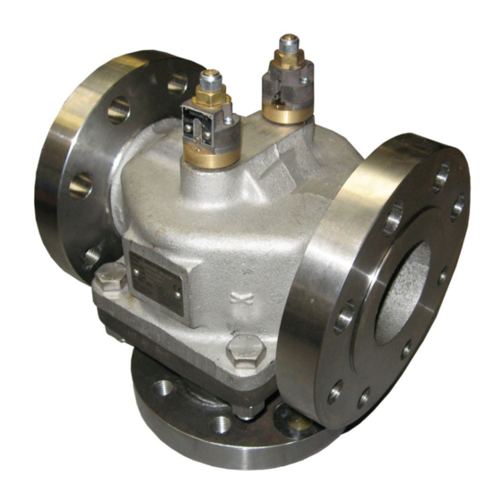
Description Section 3 Description 3.1 Overview The Model B Valve is designed to provide fully automatic, 3-way fluid temperature control for diverting or mixing applications. Typical applications include engine water jackets, lubricating oil cooling systems, and mixing and diverting of fluids in process control and industrial applications. -
Page 8: Valve Selection
3.3 Valve Selection A wide range of valve sizes and materials of construction are available, covering the applications in Section 3.2. An AMOT B Valve datasheet containing information on selection of the appropriate valve type is available, contact AMOT for a copy. - Page 9 -*** Customer special code assigned Table 1 - Model Identification * AMOT reserves the right to substitute a ductile iron product in place of cast iron to meet customer delivery requirements. Other Flange connections are available. Contact AMOT for details.
- Page 10 Description Rated Range Control Max Temp Max Temp Temp Continuous Short Period Code Crack Open Full Open °C °F °C °F °C °F °C °F °C °F 54.5 76.2 253.5 Table 2 - Element Temperatures Revision: 1 – Nov 2019 Doc No: OMMB00301...
- Page 11 Nitrile seals higher over-temperature 5566X reduce stroke with Viton seals 2433X manual override with Viton seals Table 3 - Element/Seal Types Other Elements and Seals are available. Contact AMOT for details. Doc No: OMMB00301 Revision: 1 – Nov 2019...
- Page 12 Description Revision: 1 – Nov 2019 Doc No: OMMB00301...
-
Page 13: Section 4
Use within the European Union (EU) Section 4 Use within the European Union (EU) Pressure Equipment Directive (PED) The Pressure Equipment Directive (PED) is applicable to the design, manufacture and conformity of pressure equipment and assemblies of pressure equipment with a maximum allowable pressure greater than 0.5 bar. -
Page 14: Hazardous Areas
ATEX Directive (see Section 4.2)). Users who are uncertain as to the applicability of the Pressure Equipment Directive should contact AMOT, particularly if using more hazardous (Group 1) fluids. 4.2 Hazardous Areas 4.2.1 Hazardous Area Directive (ATEX) The ATEX Directive is applicable to all equipment both electrical and mechanical that is put into service in a designated hazardous area. - Page 15 Use within the European Union (EU) Model An alphanumeric text identifier stamped onto the nameplate that fully describes the type of equipment. Serial No A unique serial number stamped on the nameplate to allow traceability of manufacture. Year The year in which the equipment was manufactured is stamped here.
-
Page 16: Specific Conditions Of Use
Use within the European Union (EU) CE mark on the AMOT B Valve only represents compliance to the ATEX Directive and not to other EU Directives. Name and address Equipment complying with the Hazardous Area Directive must be marked with the... -
Page 17: Machinery Directive
Components are only intended to be incorporated into or assembled with other machinery or equipment thereby forming Machinery. The AMOT B valve must not put into service until the Final Machinery into which it is to be incorporated has been declared in conformity with the relevant provisions of EU Machinery Directive 2006/42/EC where appropriate. - Page 18 Use within the European Union (EU) Revision: 1 – Nov 2019 Doc No: OMMB00301...
-
Page 19: Section 5
5.1 Installing the valve 5.1.1 Before starting installation 1. Upon receipt, the valve should be checked for damage sustained in shipping. All AMOT valves have nameplates attached, which are stamped with the valve model number and serial number. 2. Understand the intended use of the valve as described in Section 3. -
Page 20: Mounting The Valve In The Pipe
Installation 5.1.2 Mounting the Valve in the Pipe The valve may be mounted in any orientation; but should be properly supported and not subjected to excessive bending. Ensure the pipe flange connections are correctly aligned to avoid stressing the valve body. -
Page 21: Section 6
Operation Section 6 Operation 6.1 Operation The Model B Valve is completely automatic in operation, and needs no power supply The temperature control power is created by the expansion of a wax/copper mixture which is highly sensitive to temperature changes. Large forces are created by the warming/expansion of the mixture which in turn acts upon the sliding valve, thus regulating the flow. -
Page 22: Diverting Applications
Operation 6.1.1 Diverting applications (controls outlet temp from load source) In diverting applications temperature is sensed at port A, which remains open to port B (bypass) until the fluid temperature reaches a point 3-6°C (5-10°F) below the nominal setting, when the valve will start to move, progressively closing port B and opening port C (the cooler connection). -
Page 23: Manual Override (If Fitted)
Operation 6.1.3 Manual override (if fitted) CAUTION Manual override is for emergency use only. If operated incorrectly, damage to the valve can occur. 1. If emergency cooling is required then firstly loosen the locknut on the top of the override (reference Section 7.1, Figure 2, Item 38). - Page 24 Operation Revision: 1 – Nov 2019 Doc No: OMMB00301...
-
Page 25: Section 7
To obtain maximum service life from the valve, periodic inspection and cleaning should be incorporated into a normal preventative maintenance program. Properly applied and installed AMOT thermostatic valves require minimal maintenance. Inspection at 2 year intervals is adequate to detect normal wear. -
Page 26: Dismantling The Valve
Maintenance 7.1 Dismantling the valve Figure 2 - Diagram showing 4” B valve with manual override Figure 3 - Diagram showing 6” B steel valve without manual override Revision: 1 – Nov 2019 Doc No: OMMB00301... -
Page 27: Reassembling The Valve
Maintenance Refer to Figure 2. Remove housing nuts (Item 12) and split valve. Remove the lower housing (Item 2) taking care not to damage the elements. Remove and discard housing gasket (Item 9) ensuring any traces of the gasket are removed from the housing mating faces. - Page 28 Maintenance For 5”, 6” and 8” steel BO valve, lightly grease ‘O’ ring (Item 17) and slide over cap plate (Item 44). Secure housing to cap plate with screws (Item 28) and Loctite 241. Go to step 11. For BR valves. Lightly grease ‘O’ ring (Item 17) and slide over override stem and seat into recess in the stem adaptor followed by the ‘O’...
-
Page 29: User Maintenance Parts
Element assembly, higher over-temperature with manual override 6836S(°F) Element assembly, ‘Saltwater’ plated 6938S(°F) Element assembly, ‘Saltwater’ plated, with manual override Table 6 - Element assembly part numbers Other Elements are available. Contact AMOT for details. Doc No: OMMB00301 Revision: 1 – Nov 2019... - Page 30 Maintenance Table 7 provides the part numbers for spare seal kits, containing the required seals to maintain a complete valve. Seal Kits Material Size BO/BC/BF/BH Nitrile Viton Neoprene Nitrile Viton Neoprene 1.1/2” 46342X151 46342X152 46342X153 46342X154 46342X155 46342X156 2” 46342X201 46342X202 46342X203 46342X204 46342X205 46342X206 2.1/2”...
-
Page 31: Section 8
Trouble shooting Section 8 Trouble shooting In the event that the cooling system does not operate close to the desired temperature, the following guide may help to identify or locate the problem. 8.1 System temperature too cold 1. Insufficient heat rejected to coolant to maintain temperature. 2. - Page 32 Trouble shooting Revision: 1 – Nov 2019 Doc No: OMMB00301...
-
Page 33: Section 9
Technical Specification Section 9 Technical Specification 9.1 General valve specification 9.1.1 Materials Body materials ........Aluminium, Bronze, Cast Iron, Ductile Iron, Steel, Stainless steel Internal materials (elements) ........Stainless Steel and Bronze Option: Nickel plating Seal material ........... Nitrile, FKM (Viton), Neoprene or Ethylene propylene rubber 9.1.2 Maximum working pressure (bar) Type... -
Page 34: Valve Handling
Technical Specification 9.1.4 Valve handling Suitable care must be taken to avoid injury when handling valves. The mass of the units varies between 11 kg (25 lb) and 372kg (820 lb), depending on size and material. See Table 9 for details of all variations (all weights in Kg). - Page 36 Tel: +44 (0) 1284 762222 Fax: +1 (713) 559 9419 Fax: +44 (0) 1284 760256 Email: sales@amotusa.com Email: info@amot.com AMOT Controls GmbH Rondenbarg 25 22525 Hamburg Germany Asia and Australasia Tel: +49 (0) 40 8537 1298 AMOT Shanghai Tel: +49 (0) 40 8537 1331 Bd.
Need help?
Do you have a question about the B Series and is the answer not in the manual?
Questions and answers