
Related Manuals for Huawei OptiX PTN 3900


Summary of Contents for Huawei OptiX PTN 3900
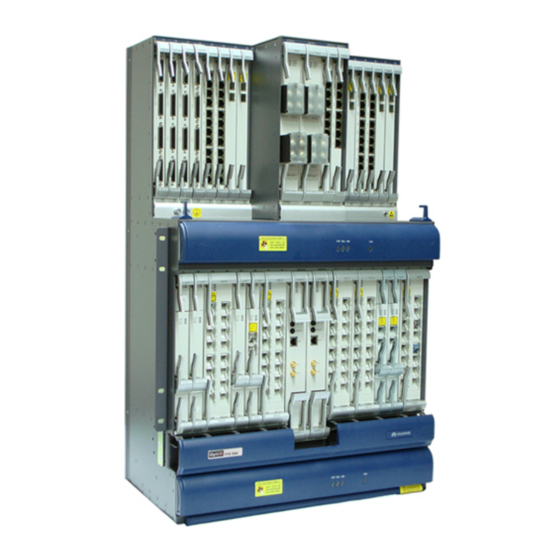
- Page 1 OptiX PTN 3900 Packet Transport Platform of PTN Series Quick Installation Guide Issue: 14 Date: 2013-07-30 HUAWEI TECHNOLOGIES CO., LTD.
- Page 2 Notice The purchased products, services and features are stipulated by the contract made between Huawei and the customer. All or part of the products, services and features described in this document may not be within the purchase scope or the usage scope. Unless otherwise specified in the contract, all statements, information, and recommendations in this document are provided "AS IS"...
- Page 3 Precautions NOTE This document aims to provide simple and distinctive guidelines for hardware installation. This document does not describe operations for the pre-delivery installation. Instead, this document describes only the operations for on-site installation. Electrostatic Discharge Before touching the device, or holding the boards and IC chips, wear the anti-static wrist strap to prevent the electrostatic discharge of the human body from damaging the sensitive components.
- Page 4 Instructions and Precautions for Handling Boards Do not hold a board without hand protection. Wear an ESD wrist strip or ESD gloves before handling a board. Wearing ESD gloves Wearing an ESD strip Holding aboard without hand protection Hold the front panel of a board with hands. Insert filler panels into vacant slots on an NE to prevent foreign matters from getting into the NE, which may result in faults on the NE.
- Page 5 Tools for Installation Tape measure Philips screwdriver Flathead screwdriver Adjustable wrench Socket wrench Paper knife Crimping pliers Cable cutter Wire stripper Coax stripper Ethernet cable crimping pliers Diagonal pliers Torque spanner Cable tester Multimeter Electric soldering iron Hydraulic crimper Heat gun...
-
Page 6: Table Of Contents
Contents Installing the Cable Distribution Plate Installing and Routing Cables Overview of Cables Cabling Holes on the Top and at the Bottom of the Cabinet Installing and Routing Power Cables Installing and Routing Cabinet Indicator Cables Installing and Routing Alarm Cables Installing and Routing E1 Cables Installing and Routing Ethernet Cables Installing and Routing External Clock and Time Cables... -
Page 7: Installing The Cable Distribution Plate
Installing the Cable Distribution Plate 37th hole Panel screw 36th hole Cable distribution plate 22nd hole 1st hole The holes are numbered from the bottom up. The hole at the bottom is numbered 1. The 73rd and 74th holes are for installation of the upper cable distribution plate . -
Page 8: Installing And Routing Cables
Installing and Routing cables Overview of Cables -48V power cable BGND power cable PGND cable Subrack power Subrack power 75-ohm 8 x E1 cable (negative) cable(positive) cable(1) 120-ohm 8 x E1 Alarm output and Cabinet indicator cable concatenation cable cable One-Channel clock Two-Channel clock transfer cables... -
Page 9: Cabling Holes On The Top And At The Bottom Of The Cabinet
Installing and Routing cables Cabling Holes on the Top and at the Bottom of the Cabinet holes on the top of the cabinet Cabling Cabling hole Cabling hole Cabling hole Cabling hole 600mm 143mm 62mm 188mm 81mm 300mm 66mm Fiber hole 251mm Fiber hole Power cable hole... -
Page 10: Installing And Routing Power Cables
Installing and Routing cables Installing and Routing Power Cables - Connection of Power Cables (TN81PDU) Cabinet grounding PGND cable Subrack power cable To office power supply Office grounding PWRA PWRA PWRB PWRB Subrack RTN1(+) NEG1(-) RTN1(+) NEG1(-) power cable connector RTN2(+) NEG2(-) RTN2(+) NEG2(-) Power cables are classified into cabinet power cables and subrack power cables. -
Page 11: Installing And Routing E1 Cables
Installing and Routing cables Installing and Routing Power Cables - Connection of Power Cables (DPD63-8-8) Cabinet grounding PGND cable To office power supply Subrack power cable Office grounding PWRA PWRA PWRB PWRB Subrack RTN1(+) NEG1(-) RTN1(+) NEG1(-) power cable connector RTN2(+) NEG2(-) RTN2(+) NEG2(-) Power cables are classified into cabinet power cables and subrack power cables. -
Page 12: Installing And Routing Ethernet Cables
The power output terminal at side A of the DC PDU provides two channels of power supplies to the PIU housed in slot 27 of the OptiX PTN 3900 subrack. The power output terminal at side B of the DC PDU provides two channels of power supplies to the PIU housed in slot 28 of the subrack. - Page 13 Installing and Routing cables Installing and Routing Power Cables - Power Distribution Unit (DPD63-8-8) The PDU (DPD63-8-8) consists of two parts: A and B, which backs up each other. Both A and B receive four - 48V/-60V power supplies and output four power supplies for subracks in the cabinet. 1 Power supply input area 2 Power supply output area 3 Power supply input area...
- Page 14 Installing and Routing cables Installing and Routing Power Cables -Installing Copper Plates on Site (TN81PDU) Do not install the copper plates in the power supply output area of the DC PDU. You should determine whether the copper plates are installed in the power supply input area only according to the on-site power supply situation.
- Page 15 Installing and Routing cables Installing and Routing Power Cables -Installing Copper Plates on Site (DPD63-8-8) Do not install the copper plates in the power supply output area of the DC PDU. You should determine whether the copper plates are installed in the power supply input area only according to the on-site power supply situation.
- Page 16 Installing and Routing cables Installing and Routing Power Cables - Upward Cabling (TN81PDU) Do not install or demount the power cable while the power is on. To avoid personal injuries, turn off the power before performing the operations. To office power supply (4×63A) BGND power cable -48V power cable PGND cable...
- Page 17 Installing and Routing cables Installing and Routing Power Cables - Upward Cabling (DPD63-8-8) Do not install or demount the power cable while the power is on. To avoid personal injuries, turn off the power before performing the operations. To office power supply (4×125A) The signal cable, power cable and fiber should be routed and bundled separately.
- Page 18 Installing and Routing cables Installing and Routing Power Cables - Downward Cabling Do not install or demount the power cable while the power is on. To avoid personal injuries, turn off the power before performing the operations. The signal cable, power cable and fiber should be routed and bundled separately. Connect these cables in sequence: PGND cable >...
- Page 19 Installing and Routing cables Installing and Routing indicator cables Cabinet indicator cable Cabinet indicator concatenation cable LAMP1 To the cabinet indicator SLOT 29 LAMP1 LAMP2 SLOT 29 Use the cabinet indicator cables to connect the LAMP1 interface of the SCA in the upper subrack and the LAMP2 interface of the SCA in the lower subrack.
- Page 20 Installing and Routing cables Installing and Routing Alarm Cables - Alarm Interfaces Alarm concatenation and output interface (ALMO1) Funciton Alarm output signal 1 (positive) Alarm output signal 1 (negative) Alarm output signal 2 (positive) Alarm concatenation signal1 (positive) Alarm concatenation signal 1 (negative) Alarm output signal 2 (negative) Alarm concatenation signal 2 (positive) Alarm concatenation signal 2 (negative)
- Page 21 Installing and Routing cables Installing and Routing Alarm Cables — Connection of the Alarm concatenation To alarm monitor To alarm monitor Orange PIN1 Upper subrack PIN2 Orange-white PIN3 Green PIN4 Blue PIN5 Blue-white PIN6 Green-white PIN7 Brown PIN8 Brown-white PIN1 Blue PIN2 Blue-white...
- Page 22 Installing and Routing cables Installing and Routing E1 cables - Upward Cabling The printed pin assignment table of the E1 cable is attached in the package. Do not discard it before installation. Cabling on the left is taken as an example and cabling on the right is similar. When you route cables on one cabinet side, the E1 cables can be layered up three layers.
- Page 23 Installing and Routing cables Installing and Routing E1 Cables - Downward Cabling The printed pin assignment table of the E1 cable is attached in the package. Do not discard it before installation. Cabling on the left is taken as an example and cabling on the right is similar. When you route cables on one cabinet side, the E1 cables can be layered up three layers.
- Page 24 Installing and Routing cables Installing and Routing Ethernet Cables - Upward Cabling The Etherent cables of the lower subrack and the Ethernet cables of the upper subrack are upward routed in the same manner, except for that the Ethernet cables of the lower subrack are upward routed from the cable distribution frame to the closest cabinet side, and finally to the cabinet cabling frame.
- Page 25 Installing and Routing cables Installing and Routing Ethernet Cables - Downward Cabling The Ethernet cables of the lower subrack and the Ethernet cables of the upper subrack are downward routed in the same manner.
-
Page 26: Installing And Routing External Clock And Time Cables
Installing and Routing cables Installing and Routing External Clock and time Cables 120-ohm clock and time interface 75-ohm clock and time interface To other equipent Select a correct clock cable according to the type of the clock and time interface on the opposite equipment. The layout of the external clock cable after it is routed out from the cabling trough is same as that of the E1 cable. - Page 27 Installing and Routing cables Installing and Routing External Clock/Time Cables - Making External Time/Clock Cables The OptiX PTN equipment supports 75-ohm and 120-ohm external clock/time interfaces. Select a correct clock/time cable according to the type of the clock/time interface on the opposite equipment. In the case of the 75-ohm external clock cable, use the bending SMB connector;...
-
Page 28: Installing And Routing Network Management Cables
The network cables are classified into the cross-over network cable and straigth through network cable. In the case of connection of the OptiX PTN 3900 to the PC, use the cross-over network cable. In the case of connection of the OptiX PTN 3900 to the switch or hub, use the straight through network cable. -
Page 29: Installing And Routing Fibers
Installing and Routing Fibers Installing and Routing Fibers - Open Corrugated Pipe Lead fibers through the corrugated pipe Open corrugated pipe Inner pipe Outer pipe Perform the following steps to place fibers into the corrugated pipe. Place the fibers straight and neatly. Cut a certain length of the corrugated pipe according to the fiber length. -
Page 30: Upward Cabling
Installing and Routing Fibers Installing and Routing Fibers - Upward Cabling When handling optical fibers, do not stand close to or look into the optic al fiber outlet directly with naked eyes. If the two fiber holes have insufficient space for the fibers, you can also route fibers through the cable hole. The pipe should extend into the cabinet by certain length so that the fibers routed in the cabinet is not in contact with the upper beam. -
Page 31: Downward Cabling
Installing and Routing Fibers Installing and Routing Fibers - Downward Cabling When handling optical fibers, do not stand close to or look into the optic al fiber outlet directly with naked eyes. Fibers are in the cabling trough If the two fiber holes have insufficient space for the fibers, you can also route fibers through the cable hole. The pipe should extend into the cabinet by certain length so that the fibers routed in the cabinet is not in contact with the upper beam. -
Page 32: Checking The Installation
Checking the Installation The subrack must be installed firmly in the position specified in the engineering design document. Empty slots in the subrack must be covered with filler panels. The air intake and exhaust vents of the device cannot be blocked to ensure proper heat dissipation. The routing of the cables must conform to the engineering design document and must facilitate maintenance and expansion in the future. -
Page 33: Connecting The Equipment Power Supply
Connecting the Equipment Power Supply Shut down the power supply to the cabinet before measuring resistance between the power input terminals of the DC PDU. If you measure the resistance with power on, personal injuries may result. Measure the resistance between the input terminals of the power box. Use a multimeter to measure the resistance between the input terminals of the power box. -
Page 34: Appendix
Appendix 1 Expanding Power Inputs During expanding and routing new external power cables, ensure that at least one power supply (active power or standby power) input to the subrack is normal according to the preceding operation. Therefore, the existing subracks are working normally. If new equipment is not configured with sufficient external power inputs according to the standard configurations of a cabinet, Instead, if it is configured with external power inputs according to the number of actually configured subracks and is not configured with external power cables for subsequent expansion in... - Page 35 • You are recommended to reserve a space of 100 mm between the OptiX PTN 3900 and the upper CRPC frame and a space of 25 mm between the two CRPC frames for heat dissipation. Do not place any thing at the air intake and air exhaust vents of the CRPC frames;...
- Page 36 Appendix 2 Installing the CRPC Frame and CRPC Board 3. Routing Cables Connect the working and protection power cables of the CRPC frame to the power ports of the frame. Route the power cables along the cable routing area on the right side of the cabinet to the power cable terminal blocks in the PDU at the top of the cabinet.
- Page 37 HUAWEI TECHNOLOGIES CO., LTD. Huawei Industrial Base Bantian Longgang Shenzhen 518129 People’s Republic of China www.huawei.com...