
Related Manuals for Evoqua V10K


Summary of Contents for Evoqua V10K
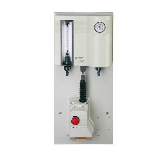
- Page 1 V10K AUTOMATIC ® WALLACE & TIERNAN VACUUM GAS FEEDER FOR Cl2 AND SO2 INSTRUCTION MANUAL...
- Page 2 Translation of the original instruction. In some countries, DEPOLOX, OSEC, Barrier, Chem-Ad and Wallace & Tiernan are trademarks of Evoqua, its subsidiaries or affiliated companies. No part of this document may be reproduced in any form (printed, photocopy, microfilm, or any other procedure) or saved, processed, copied, or distributed using electronic data systems - without the express prior written con- sent of Evoqua Water Technologies GmbH.
-
Page 3: Table Of Contents
V10k automatic Contents Introduction Documentation......................4 Conventions......................4 Safety Intended use ......................5 General safety instructions ..................5 Safety instructions specific to the V10k system ............6 Description Principle of operation....................8 Control possibilities ....................8 Design........................9 Technical Data .......................10 Installation Scope of supply .....................11 Transport and storage ...................11 Mounting.......................12... -
Page 4: Introduction
WARNING assembly, operating, and maintenance per- Electrical hazard. sonnel with the information they need for run- ning and servicing the V10k remote vacuum gas metering system. NOTICE This instruction manual contains important These notes assist in the operation of the information which will enable the operator to system. -
Page 5: Safety
Intended use The system has been constructed using the The V10k chlorinator is the central item of a best available technology and according to the disinfection system which doses chlorine gas accepted safety regulations. However, danger or sulphur dioxide gas into a flow of water. -
Page 6: Safety Instructions Specific To The V10K System
NOTICE • One of the most common causes for leaks In this manual the use of the V10k system on chlorine pipes are seals which have with chorine gas is described. The safety ins- been used more than once. For this rea-... - Page 7 Secure loose warning signs and replace when illegible. • Safety inspection once annually by a com- petent technician. • Servicing of the system at least once annually by a competent technician. We recommend concluding a servicing con- tract with Evoqua to this purpose.
-
Page 8: Description Principle Of Operation
3. Description V10k automatic Description Control possibilities The gas flow is directly indicated on the flow Principle of operation meter in g/h or kg/h. Within the dosing range, limited by the v-notch, every dosage rate can Operating water passes through an injector be adjusted (max. -
Page 9: Design
V10k automatic 3. Description Design Example for basic chlorinator installation Chlorine gas cylinder Mounting bracket Cylinder valve Vacuum control valve Activated carbon filter Pressure relief valve Pressure relief tube Chlorinator V10k Point of application 10-13 Operating water supply Injector Stop valve and injection tube... -
Page 10: Technical Data
66 sec. potentiometer 1 kOhm ± 10% Dimensions incl. mounting plate (W x H x D) V10k with positioner 369 x 880 x 185, weight approx. 15 kg The chlorinator can be equipped with different flowmeter tubes and V-notches. By changing... -
Page 11: Installation
V10k automatic 4. Installation Installation 4.2.2 Location requirements For drawings of typical installations refer to Scope of supply • Unauthorized persons must be excluded The scope of supply includes according to the from the installation. selected version: • Adequate access should be available to •... -
Page 12: Mounting
4. Installation V10k automatic Mounting body). Turn only by hand up to the stop. For measuring the injector vacuum a 1/4" con- nection is provided. WARNING Operation range: Danger due to chlorine gas (gas escape)! Up to 4 kg/h: To avoid the risk of injuries due to chlorine standard injector W3T171369 (3/4") or anti-... -
Page 13: Gas Supply Line
Max. tube/pipe length from vacuum control valve to the V10k Feed of PE hose PE hose PE hose... -
Page 14: Electric Connection
25 m 98 m 294 m 10000 1, 5 m 16 m 73 m 206 m Max. tube/pipe length from V10k to injector Feed of PE hose 6,35 PE hose 9,5 PE hose 12 PVC pipe PVC pipe PVC pipe Cl2, SO2 mm (1/4“) - Page 15 V10k automatic 4. Installation • for 115 V positioners: ø 22 mm Adjust the MIN limit To open the cover: Remove the knob (Allen key 2 mm), Unscrew the upper part of the housing. Lift the lateral brackets and pull the cover away.
-
Page 16: Insert The Flowmeter
4. Installation V10k automatic Adjust the reduced MAX limit and 14 on the board. Loosen the great output tooth wheel on the shaft below the cam wheel. Turn the tooth wheel until the ohmmeter displays between 10 and 30 ohm. -
Page 17: Remove And Mount The Cover
V10k automatic 4. Installation Slide the cover over the T-shape rails (A) of the body. Press left and right until the cover is level with the manometer and locked. A ’O-ring Preparation B Lower seat Chlorination plants should be checked by a... -
Page 18: Commissioning
Do not tolerate any leakages in the chlorine ter of the V10k is down on the lower stop. system. Immediately tighten the leak. Before servicing the system the gas supply... -
Page 19: 4.10 Training The Operator
V10k automatic 4. Installation 4.10 Training the operator Train the operator for understanding at least in safety, operation and fault finding. NOTICE The operator of the overall system must ensure that only authorized and qualified personnel can work on or with the system, and within their specified area of responsi- bility. -
Page 20: Operation
5. Operation V10k automatic Operation Changing gas containers General WARNING If the chlorinator is installed and adjusted cor- Danger due to chlorine gas ! rectly, only the following measures are neces- Chlorine gas irritates the respiratory tracts. sary during operation:... -
Page 21: Fault Finding
V10k automatic 5. Operation Fault finding WARNING To avoid personal injury by electrical energy WARNING only authorized and qualified electrical per- Danger due to chlorine gas ! sonnel may carry out works on electrical Chlorine gas irritates the respiratory tracts. - Page 22 5. Operation V10k automatic Symptoms Probable cause Remedy Injector does not meet Change injector parts. requirements. Gas filter in vacuum control Replace the filter. valve clogged. Flowmeter float Deposits on flowmeter parts. Clean flowmeter. moves erratically. Odour of chlorine in Pressure relief valve blows.
- Page 23 V10k automatic 5. Operation Symptoms Probable cause Remedy Tooth wheel defective Check toothes and clamping of tooth wheel, replace motor-gear if necessary. Rack moves to the Wrong electric wiring Check the terminals connec- wrong direction. tions (change terminal 2 and 3)
-
Page 24: Maintenance And Inspection Plan
* Maintenance level 1 can be performed by the operator/operating personnel. Maintenance level 2 must be performed by specialist technicians trained by Evoqua or the Evoqua customer service technicians. Any work over and above this may only be performed subject to prior consultation with Evoqua customer service. -
Page 25: Maintenance
Assign repairs to the Evoqua service. be replaced immediately. • Maintenance of the gas control unit is •... -
Page 26: Cleaning The Parts
6. Maintenance V10k automatic Maintenance of the chlorina‐ order, shut the filter and place again. If necessary replace the carbon as follows: Cl2 loaded carbon (at least once a year) Carry the filter to the open air. NOTICE Mix 300 g sodium thiosulphate with 8 l of water. -
Page 27: Maintenance Of The Injector
V10k automatic 6. Maintenance Remove the valve body assembly (11), Remove diaphragm (11) with clamping replace every 2 years. nut (10, 6) and spring (9). Replace gasket (13) and spring (14). Unscrew the clamping nut (10) from the Press out stem assembly (5, 6, 7, 10) from valve seat (6). - Page 28 6. Maintenance V10k automatic Injector W3T171367 up to 12. incl. Remove existing grease with alcohol. Screw out the clamping nut (17) with the Remove upper body (5). parts connected. Replace valve stem with ball head (13). Remove the valve stem (21), replace the Pay attention not to damage the ball o-ring (20).
-
Page 29: Preventive Maintenance Kits
Parts included in the kits can be replaced by competent personnel referring to the mainte- nance and safety instructions. Repairs going further may only be carried out by personnel being especially instructed by Evo- qua. Only use original Evoqua spare parts! - Page 30 W3T169197 o-ring d 9,25 x 1,78 0009 W3T170894 Shaft seal 0010 W3T168909 o-ring d 23,39 x 3,53 6.5.2 Maintenance kit W3T167494 for chlorinator V10k, automatic, 1 year Pos. Part No. Description Quant. 0001 W2T507221 o-ring d 5,28 x 1,78 0002...
- Page 31 Seat unit d 6,7 0016 W3T167443 Valve stem, complete. 0017 W3T165077 Silicone grease KORASILON Paste MV, 35 g 6.5.4 Maintenance kit W3T167024 for chlorinator V10k, automatic, 5 years Pos. Part No. Description Quantity 0001 W2T507221 o-ring d 5,28 x 1,78...
- Page 32 6. Maintenance V10k automatic 6.5.5 Set of gaskets W3T167500 for Injector 1” (W3T171367) and Injector 1” anti‐syphon (W3T171368) Pos. Part No. Description Quant. 0001 W3T161480 o-ring d 13 x 2 0002 W3T172921 o-ring d 10 x 4 0003 W3T172822 o-ring d 15,54 x 2,62...
- Page 33 V10k automatic 6. Maintenance Pos. Part No. Description Quant. 0008 W3T168917 o-ring d 75,87 x 2,62 0009 W3T159664 Valve stem 0010 W3T168867 o-ring d 40 x 3 0012 W3T161434 o-ring d 8 x 2 0013 W3T172724 o-ring d 20,22 x 3,53...
- Page 34 6. Maintenance V10k automatic 6.5.9 Maintenance kit W3T167502 for Injector 1” anti‐syphon (W3T171368), 1 year Pos. Part No Description Quant. 0001 W3T159661 Valve seat 0002 W3T161480 o-ring d 13 x 2 0003 W3T172921 o-ring d 10 x 4 0004 W3T172822...
- Page 35 V10k automatic 6. Maintenance 6.5.11 Maintenance kit W3T167032 for Injector 1” anti‐syphon (W3T171368), 5 years Pos. Part No. Description Quant. 0001 W3T159661 Valve seat 0002 W3T161480 o-ring d 13 x 2 0003 W3T172921 o-ring d 10 x 4 0004 W3T170187...
- Page 36 6. Maintenance V10k automatic 6.5.13 Maintenance kit W3T167497 for Injector ¾” (W3T171369), 1 year Pos. Part No. Desctription Quant. 0001 W3T168861 o-ring d 25 x 2,5 0002 W3T161434 o-ring d 8 x 2 0003 W3T169066 o-ring d 12,37 x 2,62...
- Page 37 V10k automatic 6. Maintenance 6.5.15 Maintenance kit W3T167026 for Injector ¾” (W3T171369), 5 years Pos. Article‐No. Description Quant. 0001 W3T159655 Inlet screw 0002 W3T168861 o-ring d 25 x 2,5 0003 W3T161434 o-ring d 8 x 2 0004 W3T159656 Valve stem...
- Page 38 6. Maintenance V10k automatic 6.5.17 Maintenance kit W3T167499 for Injector ¾” anti‐syphon (W3T171370), 1 year Pos. Part. No. Description Quant. 0001 W3T168861 o-ring d 25 x 2,5 0002 W3T161434 o-ring d 8 x 2 0003 W3T169066 o-ring d 12,37 x 2,62...
-
Page 39: Positioner
V10k automatic 6. Maintenance 6.5.19 Maintenance kit W3T167028 for Injector ¾” anti‐syphon (W3T171370), 5 years Pos. Part No. Description Quant. 0001 W3T159655 Inlet screw 0002 W3T168861 o-ring d 25 x 2,5 0003 W3T161434 o-ring d 8 x 2 0004 W3T159656... - Page 40 6. Maintenance V10k automatic Measure the winding resistance:: connect the ground (4) from the gear. Remove the 4 screws (3) and remove the terminals 4‐6 5‐6 4‐5 motor-gear assembly incl. board. 230 V 8500 8500 17000 Remove the two screws (2) and remove...
- Page 41 V10k automatic 6. Maintenance 6.6.3 Replacing the board 13 Check for function. Disconnect the positioner from the mains. 6.6.4 Replacing the motor‐gear‐as‐ Remove the knob and the cover. sembly Remove all connectors from the board Disconnect the positioner from the mains.
-
Page 42: Drawings
Holding bracket Cylinder main valve Vacuum control valve Activated carbon filter Safety relief valve Vent line Gas control unit V10k Main line being treated 10 -13 Operating water supply 14 Injector 15 Point of application 16 Vacuum safety valve 17 Contact vacuum pressure gauge... - Page 43 25 Safety unit 26 Vacuum contact pressu- re gauge 27 Room thermostat 28 Flushing light klaxon 29 Sprinkler nozzle 30 Gas leak detector GMS plus 31 Gas feed system V10k Automatik 32 Gas feed system V10k manual 33 Control unit...
-
Page 44: Mounting Drawings
7. Drawings V10k automatic Mounting drawings 7.2.1 Mounting of chlorinator V10k (with positioner) Cover removed... - Page 45 V10k automatic 7. Drawings 7.2.2 Mounting of standard injector 3/4“ W3T171369 A Gas inlet can be turned in 45° steps NOTICE Install the injector vertically (direction of flow upward!) or horizontally. Do not install hanging overhead! Nozzle Tailway W3T161564 W2T507599...
- Page 46 7. Drawings V10k automatic 7.2.3 Mounting of anti‐syphon injector 3/4“ W3T171370 A Console (W3T161479), screws (2x W2T504542) NOTICE (not included in W3T171370) Install the injector vertically (direction of B Gas inlet can be turned in 45° steps flow upward!) or horizontally. Do not install...
- Page 47 V10k automatic 7. Drawings 7.2.4 Mounting of injector 1“ W3T171367 and W3T171368 A Total length depending on tailway B Gas inlet can be turned in 60° steps NOTICE Install the injector vertically (direction of flow upward!) or horizontally. Do not install...
- Page 48 7. Drawings V10k automatic 7.2.5 Injector 3/4" with accessory A for hose ID12x2 (W2T505677) Pos. 4 and 5 tightened with teflon tape. B for hose ID9,5x1,6 (W2T505672 ) * tightened with silicone grease (W3T165077). for hose ID6,35x1,6 (W2T505671) ** cemented (PVC) Part no.
- Page 49 V10k automatic 7. Drawings Part no. Description Qty. W2T505599 Reduction d32+40-20+25 W3T167194 Reduction nipple PVC, 1/2"NPT x DN 15 W3T171372 Connector for hose 3/8 x 1/2" W3T161698 Connector 1/2-14NPT W3T171353 Connector for hose D3/8" d1/4" W3T172724 O-ring d20.22 x 3.53/FPM...
- Page 50 7. Drawings V10k automatic Anti‐syphon‐Injector 3/4" with accessory Part no. Description Qty. W3T171370 Injector 3/4" PVC-U Nozzle Tailway W3T167396 Adaptor union incl. o-ring DN25-R 3/4" d32.92 x 3.52 W3T163750 Adaptor union incl. o-ring DN 20-R 3/4 d28.17 x 3.52 W3T163705 Adaptor union incl.
- Page 51 V10k automatic 7. Drawings 7.2.7 Injector 1" with accessory A for hose ID6,35x1,6 (W2T505671). Pos. 6, 7, 9, 10, 11 tightened with teflon tape. B for hose ID9,5x1,6 (W2T505672). Pos. 15, 16 tightened with silicone grease for hose ID12x2 (W2T505677).
- Page 52 7. Drawings V10k automatic Injector 1" with accessory Part No. Description Quant. W3T171367 Injector 1" PVC/PTFE/FPM W3T171368 Injector 1" PVC/PTFE/FPM Injector throat Tailway W3T170897 Clamping screw W3T159484 Adaptor nipple PVC;R1" x 1"NPT;80lg. W3T163793 Adaptor union incl. o-ring DN 25-R 1...
-
Page 53: V10K Chlorinator
V10k automatic 7. Drawings V10k chlorinator Pos 100: Notch downward! Pos. 106-108: After adjusting the nut pos. 108 lock the nut and secure with red locking varnish. - Page 54 7. Drawings V10k automatic V10k side view Differential regulating valve in detail...
- Page 55 V10k automatic 7. Drawings Part no. Description Qty. W3T169313 Body (5") PVC, V10k W3T161817 Body (10") PVC, V10k W3T167495 Cover complete 19+60 W3T159801 Seat assembly PTFE; d6,7; above 3 kg/h W3T171294 Seat assembly PTFE; d2,6; up to 2 kg/h W3T167443...
- Page 56 7. Drawings V10k automatic Part no. Description Qty. W2T506780 Reducing bush PVC; d20-16 W3T172961 Threaded insert 1/4-18 NPT; d20; PVC W3T169110 Union PVC;1/4NPT x 1/2-20UNF-2A W3T169111 Union nut PVC; 1/2-20UNF-2B W3T171126 Hose connector for hose RP-684821 W3T169009 Union nut W3T165447...
- Page 57 V10k automatic 7. Drawings Part no. Description Qty. W3T165077 Silicone grease W2T505780 Plug GPN 500 B47; for M6 W2T503920 Cable gland PG13,5 grey; d6-12; type Skintop W2T505380 Nut PG13,5 W3T161275 Plug GPN 610 U 7 7.3.1 Flowmeters Length 5" range Spare Length 10", range...
- Page 58 7. Drawings V10k automatic 7.3.2 V‐notch Control range (for chlorine gas) Control range Spare V‐notch with shock chlorination Spare V‐notch (for chlorine gas) (lin. control range/shock chlorination) 2 - 25 g/h W3T171181 * 3 - 60 g/h W3T171282 * 3 - 60 / 120 g/h...
-
Page 59: Injectors
V10k automatic 7. Drawings Injectors 7.4.1 Injector W3T171367 (1") - Page 60 7. Drawings V10k automatic Injector W3T171367 (1") Part no. Description Qty. W3T159661 Seat PVC, 1" Injector W3T161480 O-ring d13x2/FPM W3T171124 Body PVC, 1" Injector W3T161296 Plug GPN 610 U 28 W3T172921 O-ring d10x4/75FPM602 W3T170187 Seat PVC, 1" Injector W3T172822 O-ring...
- Page 61 V10k automatic 7. Drawings 7.4.2 Anti‐syphon‐injector W3T171368 (1")
- Page 62 7. Drawings V10k automatic Injector W3T171368 (1") Part no. Description Qty. W3T159661 Seat PVC, 1" Injector W3T161480 O-ring d13 x 2/FPM W3T171118 Body PVC, 1"Inj., Anti-syph. W3T161296 Plug GPN 610 U 28 W3T172921 O-ring d10 x 4/75FPM602 W3T170187 Seat PVC, 1" Injector...
- Page 63 V10k automatic 7. Drawings 7.4.3 Injector W3T171369 (3/4") 17: Attention: Only slight screwed in.
- Page 64 7. Drawings V10k automatic Injector W3T171369 (3/4") Part no. Description Qty. W3T159655 Inlet screw PVC,3/4" Injector W3T168861 O-ring, d25 x 2,5/FPM W3T161434 O-ring d8 x 2/75FPM602 W3T159656 Valve stem PVC, 1" Injector W3T171120 Body PVC, 3/4" Injector W3T158460 Valve seat PVC, UNF½"-20Gg...
- Page 65 V10k automatic 7. Drawings 7.4.4 Anti‐syphon‐injector W3T171370 (3/4") Adjust in this position 29: Attenttion: Only slight screwed in.
- Page 66 7. Drawings V10k automatic Anti‐syphon‐Injector W3T171370 (3/4") Part no. Description Qty. W3T159655 Inlet screw PVC, 3/4" Injector W3T168861 O-ring d25 x 2,5/FPM W3T161434 O-ring d8 x 2/75FPM602 W3T159656 Valve stem PVC, 1" Injector W3T171120 Body PVC, 3/4" Injector W3T158460 Valve seat PVC, UNF½"-20Gg...
-
Page 67: Wiring Diagram
V10k automatic 8. Wiring diagram Wiring diagram Positioner drawn closed / Mode of operation: Automatic... -
Page 68: Declaration Of Conformity
9. Declaration of conformity V10k automatic Declaration of conformity... - Page 69 V10k automatic 9. Declaration of conformity...
-
Page 70: 10. Notes
10. Notes V10k automatic 10. Notes... - Page 71 V10k automatic Wallace & Tiernan® Products worldwide Australia Canada China +61 1300 661 809 +1 905 944 2800 +86 21 5118 3777 info.au@evoqua.com wtoe.can@evoqua.com sales.cn@evoqua.com France Germany Singapore +33 1 41 15 92 20 +49 8221 9040 +65 6559 2600 wtfra@evoqua.com...
- Page 72 © 2021 Evoqua Water Technologies GmbH Subject to change without notice. WT.025.101.000.DE.IM.0321 W3T163014 Issue 13-0321 Auf der Weide 10, 89312 Günzburg, Germany +49 (8221) 904-0 www.evoqua.com...
Need help?
Do you have a question about the V10K and is the answer not in the manual?
Questions and answers