
Related Manuals for SmarTrike Xtend Mg+


Summary of Contents for SmarTrike Xtend Mg+
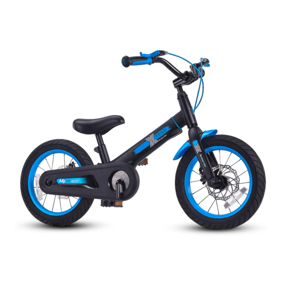
- Page 1 20601A www.smarTrike.com Ages 3-6yrs Designed to fit riders with measurements Inseam: 40-59cm/15.6-23inch ™ Height: 95-125cm/37-49inch. Max load 50kg/110lbs Teach them to ride Balance watch them go... Pedal See them fly! Bike...
-
Page 2: Assembly Parts
Assembly parts Australia BEB1501 USA/Canada BEB1502 BEB1001 BEB1512201 BEB1002 BEB1013201 BEB1004102 BEB1011201 BEB1008104 BEB1024201 BEB1509101 / BEB1020201 BEB1508101 BEB1025201 BEB1026201 BEB1027201 17mm / 0.7'' 15mm / 0.6'' NOTE: This information is only available on the bicycle itself. Each bicycle has a Recovery Code stamped into the frame. The Recovery Code... -
Page 3: Owner's Bicycle Identification Record
Owner’s Bicycle Identification Record NOTE: This information is available only on the bicycle. Under the body tube As shown in the image, our bicycle has the production date code stamped into its body (model / STB / month / year) 3 Steps to Adjust the Bike to the Rider Assemble the bike. -
Page 4: Warning And Safety Information
Warning and Safety Information Meanings of Warnings: This symbol is highly crucial. Carefully see the word “CAUTION” or “WARNING” which follows it. The word “CAUTION” is provided before mechanical instructions. In case you do not obey these instructions carefully, mechanical damage or failure of a part of the bicycle can take place. The word “WARNING”... -
Page 5: Rules Of The Road
Rules of the Road WARNING: from injury or others could be hurt. You must wear a bicycle helmet that meets the local standard and the local safety standards. Make sure to wear shoes while riding. Ride on the correct side of the road, in a straight line and in a single file. Bikes not intended for use on the public roads. - Page 6 NOTE: This information is only available on the bicycle itself. Each bicycle has a Recovery Code stamped into the frame. The Recovery Code...
- Page 7 Parts Assembly List Fitting the Description Description Frame Front Wheel Assembly Fork Tyre (x2) Handlebar Tube (x2) Grips (x2) Rear Wheel Assembly Handlebar Stem Front brake disc Seat Hand Brake Seat Post Chain Clamp Chain Cover Head Set Bearings Back Wheel Nut (x2) Right Pedal Balance Bike System Left Pedal...
- Page 8 Installing the Front Part 1. Release the screw and nut. 2. Insert the front complex into the body. 3. Tighten the screw and the nut.
-
Page 9: Handlebar And Stem Installation
Handlebar and Stem Installation 4. Unfasten the 4 stem screws. 5mm / 0.2‘’ 5a. Place the handlebar on the head tube. 5b. Reattach the stem and fasten the screws. 5mm / 0.2‘’... -
Page 10: Adjusting The Handlebar
Handlebar and Stem Installation WARNING: In order to prevent any steering system damage and possible loss of control,, the “MIN-IN” (minimum insertion) mark , on the stem must be below the top of the locknut B . NOTE: Separate the plastic cap C from the end of the stem D . STEPS: 1. -
Page 11: Seat Installation
Seat Installation WARNING: In order to According to European standards, prevent the seat from do not insert the seat further than becoming loose and a the top mark (Illustration mark C ). possible loss of control, the “MIN-IN” (minimum insertion) mark A on the seat post is placed below the top of the seat tube B . -
Page 12: Testing Stem And Handlebar Tightness
Testing Stem and Handlebar Tightness To test the tightness of the stem: Straddle the front wheel of the bike between your legs. Turn the handlebar in order to try and turn the front wheel. If the stem and handlebar turn without turning the front wheel, readjust the stem with the wheel and secure the stem bolt(s) tighter than before (about 1/2 revolution only at a time). - Page 13 To adjust the front brake – please follow these illustrations: -13-...
- Page 14 Assembly Step 1: Turn the bicycle in an upside down manner so the rear wheel is upwards. Step 2: Attach the footrest to the bottom of the frame 5mm / 0.2‘’ using 5mm /5” Allen key and 3 bolts. -14 -...
-
Page 15: Reflector Installation
Testing The Seat - Post Clamp Tightness To test the tightness of the seat-post clamp: Try turning the seat side-to-side. If the Seat Post moves in the seat tube: Tighten the Allen screw which is on the seat-post clamp. Repeat this test again, until the seat post does not move in the seat tube. Bell Feature In case the mounting screw A is factory installed remove it and set it... - Page 16 -16-...
- Page 17 Change brake leaver side To switch the brake from the right to the left side, according to the US standard, follow the instructions below: Step 1: Remove the handle grips from both sides, and keep it aside. Step 2: A. Use the 5 mm / 0.2” Allen key to loosen the screw slightly. B.
- Page 18 Step 3: Turn the brake leaver over. Step 4: A. Insert the brake leaver on the left handlebar. B. Lock and tighten the screw with the 5 mm / 0.2” Allen key. Step 5: Reattach the handlebar grips. -18-...
- Page 19 -19-...
- Page 20 Balance bike mode to pedal mode Assembly parts Step 1: Turn the bicycle in an upside down manner so the front wheel is upwards. - No need to remove the wheels - -20-...
- Page 21 Step 2: A. To loosen the 3 bolts use a 5mm/0.2 inch Allen key. B. Remove the footrest and keep for future use. C. Separate the bolts and keep them aside for next stages. Step 3: Remove the plastic cover of the gear. Step 4: A.
- Page 22 Step 5: Tighten the screws so the pedal system can be locked to the body. 5mm / 0.2‘’ Step 6: A. Remove the screw and keep it aside. Do not throw B-C. Cover the chain with the lid Until you hear a “click”. -22-...
- Page 23 D. Replace the screw and secure it for locking purpose. Chain Adjustment WARNINGS: The chain must stay on the sprockets. In case it fail to operate properly. NOTE: Ensure the rear wheel is in the WARNINGS: centre of the bicycle frame. Do not try to repair chain on your own.
- Page 24 Step 7: 17mm / 0.7'' For screwing the pedals use the open wrench (15mm /0.6” ). NOTE: 15mm / 0.6'' Pay careful attention to the side pedals according to the presented mark on the pedal side. Step 8: Place the Seat Post red reflector carefully so that it points straight backward.
- Page 25 USA & Canada Australia -25-...
-
Page 26: Extended Mode
Extended Mode Step 1: A. First, you need to loosen the screw and nut. B. The telescopic mechanism must be pulled to the required measure. C. Tighten the screw and nut for locking the mechanism. -26-... - Page 27 Step 2: A. To adjust the handlebar use the 6mm/0.23'' Allen key. B. To lock the mechanism back use the Allen Key. -27-...
- Page 28 USA & Canada Australia -28-...
-
Page 29: Repair And Service
Repair and Service WARNING: The product must be frequently inspected. A failure to inspect the product and to make repairs or necessary adjustments can lead to injury to the rider or to others. Ensure that all the parts are properly assembled and adjusted as per the written instructions in this manual and any “Special Instructions”. -
Page 30: Coaster Brakes
Coaster Brakes Follow the below guidelines to operate the coaster brake: To move the chain backward, push the pedals backward The chain will activate the coaster brake mechanism which is inside the rear wheel hub When you push the pedals backward with higher force, the coaster brake’s braking action will increase. -
Page 31: Lubrication And Maintenance
Recommended Torque Table 6 N•m 6 N•m 7 N•m 8 N•m 8 N•m 10 N•m 12 N•m 12 N•m (4.43 ft-lbs) (4.43 ft-lbs) (5.16 ft-lb) (5.9 ft-lbs) (5.9 ft-lbs) (7.38 ft-lbs) (8.85 ft-lbs) (8.85 ft-lbs) 5.5N/m 15N/m 0.7N/m 9.5N/m (4 ft-lbs) (11 ft-lbs) (0.5 ft-lbs) (7 ft-lbs) - Page 32 WARNING: ALWAYS WEAR YOUR HELMET WHEN RIDING THIS PRODUCT! Ensure that the helmet sits in a levelled manner on the head and low on the forehead. The strap sliders must be adjusted below your ear on both the sides. Make sure to buckle the chin strap and adjust the strap until it is securely fastened.
- Page 33 4 years for the frame and fork, 6 months for all Other bicycle component parts. No other express or implied warranty given. smarTrike® will make sure to replace without charge the bicycle frame, fork or those component parts which are ascertained by smarTrike...
- Page 34 All riders will presume their own risk of injury while biking, and smarTrike will not take any responsibility unless the accident and injury arise out of smarTrike’s sole negligence and such negligence has to be definitely proven.
- Page 35 -35-...
- Page 36 20628205603...
Need help?
Do you have a question about the Xtend Mg+ and is the answer not in the manual?
Questions and answers