Table of Contents
Advertisement
Quick Links
Advertisement
Table of Contents

Related Manuals for Jireh NAVIC


Summary of Contents for Jireh NAVIC
- Page 1 CX0098 Rev 07.5 Automated Steerable Scanner...
- Page 2 SAFETY WARNINGS / PRECAUTIONS KEEP THIS MANUAL – DO NOT LOSE THIS MANUAL IS PART OF THE NAVIC SYSTEM AND MUST BE RETAINED FOR THE LIFE OF THE PRODUCT. PASS ON TO SUBSEQUENT OWNERS. Ensure any amendments are incorporated with this document.
- Page 3 Pinch points exist with this product. Keep fingers and hands clear of pinch points. CAUTION! DO NOT operate the NAVIC crawler on an inspection surface which is electrically connected to a component that is being welded. PAGE ii of viii...
- Page 4 CAUTION! Do not disconnect under load. Shut off power before connection or disconnecting. Permanent damage to electronics could occur. Emergency Stop. This symbol indicates emergency stop button. The WEEE symbol indicates that the product must not be disposed of as unsorted municipal waste, but should be collected separately.
-
Page 5: Table Of Contents
TABLE OF CONTENTS Introduction Chapter 1.1. Product information 1.1.1. Intended use 1.1.2. Unintended Use 1.2. Regulations 1.2.1. FCC 1.2.2. Industry Canada 1.3. Intended User 1.4. Dimensions and Weight 1.5. Scanner Operation Specifications 1.6. Performance specifications 1.7. Maintenance 1.8. Power Requirements 1.9. - Page 6 4.3. Operation 4.3.1. Controller Layout 4.3.1.1 Touchscreen 4.3.1.2 Click Wheel 4.3.1.3 Joysticks 4.3.2. Main Mode Selection Screen 4.3.3. Jog Mode 4.3.4. Latched Jog Mode 4.3.5. Two Axis Scan Mode 4.3.5.1 Two Axis Scan Setup Screen 4.3.5.2 Scan Speeds Screen 4.3.5.3 Two Axis Scan Screen 4.3.6.
- Page 7 5.5.1. HydroFORM™ Probe Holder 5.5.2. Heavy Duty Vertical Probe Holder 5.5.2.1 Probe Holder Setup 5.5.2.2 Probe Holder Vertical Adjustment 5.5.2.3 Probe Holder Left/Right Conversion 5.5.2.4 Probe Holder 90° Adjustment 5.5.3. Corrosion Thickness Probe Holder 5.5.4. Two Probe Raster Arm 5.5.5. Pivoting the Raster Arm 5.5.6.
- Page 8 5.17.2. Zipper Tube Setup 5.17.3. Clamp Setup 5.18. Backpack 5.19. Preamp Bracket Maintenance Chapter 6.1. Safety Precautions Before Maintenance 6.2. Maintenance Schedule Troubleshooting Chapter 7.1. Startup Issues 7.1.1. Joystick Off Center 7.1.2. Checking Network 7.2. Startup Override 7.2.1. Scan Devices 7.2.2.
- Page 9 9.12.4. Pivot Button Style 9.13. Variable Components 9.13.1. Frame Bar 9.13.2. Cable Management 9.13.2.1 Cable Management Sleeving 9.14. Encoder Connector Type 9.15. Accessories 9.15.1. Battery Powered Optical Guide 9.15.2. Preamp Bracket 9.15.3. NAVIC Backpack Limited Warranty Chapter PAGE viii of viii...
- Page 10 CX0098 Rev 07.5 PAGE 1 of 131...
-
Page 11: Introduction
1.36 kg (3 lb) ► are attached to the NAVIC via a tether or probe cables strong ► enough to prevent the object from falling have smooth edges so as not to cut backpack strap ►... -
Page 12: Unintended Use
► than 1.36 kg or objects that are not attached to the NAVIC via a (3 lb) tether or probe cables, or objects with sharp edges CX0098 Rev 07.5... -
Page 13: Regulations
Cet appareil numérique de la classe A est conforme à la norme NMB-003 du Canada. 1.3. Intended User The NAVIC is intended to be used by persons who have read and understood this user manual. , the NAVIC is intended to be used... -
Page 14: Dimensions And Weight
1.4. Dimensions and Weight WARNING! LIFTING HAZARD. The NAVIC can be heavy. Single person lift could cause injury. Two person lift recommended. Crawler weight* 7.7 kg 17 lb Crawler dimensions** 21 x 2 5 x 8 cm 8.3 x 1 0 x 3 .2 in... -
Page 15: Performance Specifications
1.6. Performance specifications Crawler vertical payload:* 10 kg 22 lb Drive module speed 0 - 25 cm/sec 0 - 10 in/sec Raster arm module speed 0.5 - 76.2 cm/sec 0.2 - 30 in/sec * Performance may vary with surface type. **Heavy payloads may require reduced speeds. -
Page 16: Operating Environment
NAVIC NOTE: The power supply automatically adjusts to the supplied voltage. 1.9. Operating Environment The NAVIC is designed for use in an industrial environment that is between -20° C and 50° C (-4° F) (122° F) 1.10. Definition of symbols Instructions to ‘look here’... -
Page 17: Included Tools
Fig. 2 The included 3 mm hex driver (Fig. 1) suitable for most typical adjustments of the NAVIC modules. Also included in this kit is a 3/8 in wrench which is used to remove and install (Fig. 2) probe holder buttons. -
Page 18: Preparation For Use
2.1. Transportation CAUTION! PINCH / CRUSH HAZARD. BE CAREFUL when passing the NAVIC crawler through narrow ferrous (magnetic) openings, such as man-holes. The magnetic drive wheels can cause bodily harm if allowed to slam onto the walls of the opening. -
Page 19: Tether Requirements And Attachment
Before placing the crawler on the surface to be inspected , attach the (e.g. tank) provided lifting sling to the NAVIC and then hook the tether hook to the lifting sling. CAUTION! The overhead attachment point for the tether must be located as close as possible to a... -
Page 20: Lifting Sling Setup
Ensure the tether hook does not have sharp edges that may cut the lifting sling. 2.3.1. Lifting Sling Setup Secure the lifting sling to the NAVIC as indicated here: - Lift tether attachment points Fig. 9 Lift the two tether attachment points (Fig. - Page 21 Simultaneously press the pin’s release button and pull the pin (Fig. 10) from the shackle (Fig. 11) - Insert pin - Align shackle with tether holes Fig. 12 Fig. 13 Slide the shackle around the tether attachment point (Fig. 12) Align the tether attachment point and shackle.
-
Page 22: Lifting Sling Low Profile Setup
2.3.2. Lifting Sling Low Profile Setup The following adjustment allows low profile scanning when required. - Proper shackle setup - Proper shackle setup Fig. 16 Fig. 17 The shackle plate in conjunction with the tether attachment point (Fig. 16) provides the necessary clearance for scanning equipment. Reverse the lifting sling and shackles so that the shackles are free to (Fig. -
Page 23: Scanner Component Identification
2.5. Scanner Component Identification The NAVIC system can contain the following components (see System Components on page 43 for additional details) - Navic (crawler) - Power supply - Umbilical Fig. 18 Fig. 19 Fig. 20 - Handheld controller - Encoder cable - Controller cable Fig. - Page 24 - Probe holder frame - Low profile probe holder - Pivoting probe holder frame Fig. 30 Fig. 31 Fig. 32 frame - HydroFORM™ probe holder Fig. 34 - Raster arm - Corrosion thickness probe Fig. 33 Fig. 35 holder CX0098 Rev 07.5 PAGE 15 of 131...
-
Page 25: Configurations
Chapter 3 CONFIGURATIONS 3.1. Single Drive Module with Frame Bar 1 10 BOM ID Description BOM ID Description Instrument Umbilical (Operator) Power Supply Encoder Cable Controller Controller Cable Right Drive Module Controller Cable Umbilical Power Cable (Crawler) Frame Bar - Single pod configuration Fig. - Page 26 To configure the NAVIC system for scanning using a single drive module with a frame bar, follow these steps: CAUTION! Do not disconnect under load. Shut off power before connection or disconnecting. Permanent damage to electronics could occur. Separate the left and right crawler modules (see “Connecting/Disconnecting Left...
-
Page 27: Dual Drive Module With Probe Holder Frame
3.2. Dual Drive Module with Probe Holder Frame 7 11 Description BOM ID Description BOM ID Instrument Encoder Cable Power Supply Controller Cable Controller Controller Cable Right Drive Module Power Cable Umbilical Left Drive Module (Crawler) Umbilical Probe Holder Frame (Operator) - Dual pod with rack configuration Fig. - Page 28 To configure the NAVIC system for scanning using dual drive modules with a probe holder frame, follow these steps (see “Probe Holder Frame” on page 89) CAUTION! Do not disconnect under load. Shut off power before connection or disconnecting. Permanent damage to electronics could occur.
-
Page 29: Dual Drive Module With Raster Arm Module
3.3. Dual Drive Module with Raster Arm Module 7 11 Description BOM ID Description BOM ID Description BOM ID Instrument Umbilical (Crawler) Controller Cable Power Supply Umbilical (User) Power Cable Controller Encoder Cable Left Drive Module Right Drive Module Controller Cable Raster Arm Module - Dual drive module with raster arm configuration Fig. - Page 30 To configure the NAVIC system for scanning using a dual drive module and a raster arm module, follow these steps (see Raster Arm Module on page 51 for additional details) CAUTION! Do not disconnect under load. Shut off power before connection or disconnecting.
-
Page 31: Operation
Chapter 4 OPERATION 4.1. System Startup - Power supply Fig. 39 To activate the system, follow these steps: Plug-in the power supply to the appropriate power source (see “Power Requirements” on page 6) Connect the components (see “Configurations” on page 16) Locate the red emergency stop push-button on the power supply. - Page 32 A warning message will display on the controller when power has been activated. Once the dangers of using the NAVIC are recognized and understood by reading this user manual, touch Ok to acknowledge the warning. *** DANGER *** HAVE YOU IMPLEMENTED...
-
Page 33: Placement Of Crawler On Inspection Surface
4.2. Placement of Crawler on Inspection Surface IMPORTANT! To place the crawler on the inspection surface, use the scanner installation/removal as a spacer between the wheels and the (Fig. 28) surface on which the crawler is to drive. This is necessary to protect the electronic components within the crawler from damaging shock, should the crawler be slammed directly onto the surface. - Page 34 - Place installation/removal mat - Lower crawler to mat Fig. 44 Fig. 45 Place the installation/removal mat on the inspection surface (Fig. 28) (Fig. 44) WARNING! MAGNETIC MATERIAL. The installation/removal mat contains magnetic material. Those with pacemakers or ICD’s must stay at least 10 away.
-
Page 35: Operation
TIP: Avoid the drive modules slamming to the inspection surface. This can occur when all four wheels are not in contact with the installation/removal mat while the crawler is driven onto the inspection surface. Remove the installation/removal mat from the inspection surface. Check that the trailing wheel encoder is in contact with the inspection surface, adjust if required (see “Encoder”... -
Page 36: Touchscreen
Net Status: 05000000 Last Error: 00118130 Status Word: 1217 4.3.1.1 Touchscreen Current mA: The controllers touchscreen is the primary operator interface (Fig. 49-5) for the system. Buttons are indicated on-screen with a 3D border Temperature: (Fig. 50). PREV NEXT Exit - Sample touchscreen buttons Fig. -
Page 37: Jog Mode
4.3.3. Jog Mode Jog mode manually controls the system movement using the joysticks. SCAN SCAN Zero Crawler Crawler Raster Zero 76mm/s 76mm/s 92mm/s Right Joystick= Raster Exit Exit - Jog mode with raster arm - Jog mode Fig. 52 Fig. 53 NOTE: Jog mode is the default selection when the system is first activated. - Page 38 When the right crawler module is connected, the crawler position displayed refers to the position of the auxiliary idler encoder which is located between the module’s wheels. NAVIC NOTE: This function only zeroes the number displayed on the controller. It does not zero the position used in the data acquisition instrument.
-
Page 39: Latched Jog Mode
4.3.4. Latched Jog Mode SCAN Zero Crawler Raster 76mm/s 92mm/s Screen or Knob to STOP Right Joystick= Raster Exit - Latched Jog Mode Fig. 55 Identical to standard jog mode, latched jog mode adds forward or reverse crawler movement at the selected scan rate. This eliminates the need to manually hold the left joystick (see “Jog Mode”... -
Page 40: Two Axis Scan Setup Screen
4.3.5.1 Two Axis Scan Setup Screen Two Axis Scan Setup Scan Index Index Path Speed Exit - Two axis scan setup Fig. 56 The Two Axis Scan Setup screen is used to program the desired scan pattern the system will use. Point A –... -
Page 41: Scan Speeds Screen
Index B Must Be Less Than Index C - Run button error Fig. 59 Run Button: Initiates a check of the input values to ensure they are within the system capabilities. When a scan pattern is invalid or out of range points entered, a warning will be displayed . -
Page 42: Two Axis Scan Screen
4.3.5.3 Two Axis Scan Screen Two Axis Scan Scan Index AuxEnc Start Reset Exit - Two axis scan screen Fig. 61 The Two Axis Scan screen initiates and monitors the two axis scan. The screen displays a visual representation of the scan area . - Page 43 During a scan, a graphical representation of the scanner path is displayed (Fig. 62) Two Axis Scan Scan 178mm Index 166mm AuxEnc 177mm Stop Reset Exit - Scan path close up Fig. 63 When the scanner reaches the scan area, the graphic zooms to display that scan area.
-
Page 44: System Utilities Screen
4.3.6. System Utilities Screen Utilities User Settings Diagnostics Touch Cal Joystick Cal Draw Bounce Exit - Utilities screen Fig. 65 The Utilities screen provides access to the setup, diagnostics and user preference settings. User Settings Button: Access the User Settings screen allowing for various user preferences to be adjusted. - Page 45 TITLE DESCRIPTION VALID DEFAULT RANGE Units In=0/MM=1 Changes the measurement units for display and user entry. When set to 0, units measure in inches. When set to 1, units measure in millimeters. Scan Steering Sets the steering limit maximum 0-100 when using the jog mode scan %max setting.
-
Page 46: Diagnostics Screens
*Raster Flip 0/1 Set raster arm orientation. When the raster arm is mounted with the motor housing to the left of the crawler, the appropriate setting is 1. When the raster arm is mounted with the motor housing to the right of the crawler, the appropriate setting is 0. -
Page 47: System 1
4.3.6.2.2. System 1 Diagnostics System 1 PowerOnTime: 55:48:42 Reset Cause: ResetInt: EEpromCheck: Joysticks: Touchscreen: 2683 3486 PREV NEXT Exit - Diagnostic screen Fig. 68 System 1 diagnostic screen displays general system function information. POWERONTIME The total accumulative time the handheld controller has been powered. -
Page 48: System 3
4.3.6.2.4. System 3 Diagnostics System 3 IntAddr: 0000 IFS0: 0100100000000000 IFC0: 1000000000001000 IPC0: 5444 6444 Timer: 2837 PREV NEXT Exit - Diagnostic screen Fig. 70 The System 3 Diagnostic screen displays additional system information. The information provided does not typically assist the user. -
Page 49: Touch Calibration Screen
Diagnostics RightDrv AuxEncPos: EncPos: Stator: Commutation: Motor Stat: 00000000 PREV NEXT Exit - Diagnostic screen Fig. 72 AUXENCPOS Displays the position of the auxiliary encoder in counts when connected to the module. When the auxiliary encoder is moved, this number will change. When the encoder is moved from its current position and then back to that exact same position, this number will also return to its original position. -
Page 50: Joystick Calibration Screen
4.3.6.4 Joystick Calibration Screen Left Joystick off Center and Will be Disabled. - Joystick error Fig. 74 Typically joystick calibration is only necessary when a joystick off center error is detected upon startup . Calibration may also be (Fig. 74) used when a joystick function does not appear to be properly centred. -
Page 51: Draw
4.3.6.5 Draw - Draw utility Fig. 76 The draw utility may be used to test the function of the touchscreen. Exit the utility by pressing the click wheel. PAGE 42 of 131... -
Page 52: System Components
Chapter 5 SYSTEM COMPONENTS 5.1. Controller - Controller Fig. 77 The controller is used to manipulate a scanner installed on an inspection surface. User settings and scan information are edited using the controller. The controller is connected to the umbilical with the controller cable The controller contains the complete system program and must be connected for the system to operate. -
Page 53: Right Drive Module
Fig. 78 - Right drive module The right drive module includes the encoder, umbilical connections and accessory mounting point. When connected with the left drive module the NAVIC scanner is able to steer on an inspection surface. NOTE: Steering is limited on smaller diameter inspection surfaces. -
Page 54: Umbilical
- Align dovetail jaws - Mount frame bar Fig. 81 Fig. 82 Alternatively, accessories can also be mounted straight to the swivel mount. Rotate the black wing knobs aligning the dovetail jaws with the mount’s grooves . Press the frame bar or accessory to the swivel mount (Fig. -
Page 55: Encoder
Align the umbilical to the umbilical mount of the drive module (Fig. 85) - Tighten knob - Adjust umbilical mount angle Fig. 86 Fig. 87 Tighten the black wing knob to fasten the umbilical to the crawler (Fig. 86) The right drive module’s umbilical mount can pivot to allow low profile scanning. -
Page 56: Handle
5.2.4. Handle - Lift handle lock latch - Pivot handle nose down Fig. 90 Fig. 91 The handle is removable to achieve low profile scanning. To remove the handle, lift the handle lock latch . Pivot the handle (Fig. 90) down and then pull the (Fig. -
Page 57: Left Drive Module
- Left drive module Fig. 93 The left drive module is only used in conjunction with the right drive module. Combining both modules allows the NAVIC scanner to steer on an inspection surface. NOTE: Steering is limited on smaller diameter inspection surfaces. -
Page 58: Encoder
The front mount pivots freely and cannot be locked in a fixed position. (Fig. 95) When a frame bar is connected to both dovetail mounts on the two modules, this free movement allows the scanner to flex while steering. TIP: Alternate mounting procedure is possible (see Swivel Mount on page 44 for additional details). -
Page 59: Connecting/Disconnecting Left And Right Modules
- Press release pin - Press pin and rotate modules Fig. 97 Fig. 98 Locate the release pin at the bottom of the NAVIC . Using the (Fig. 97) supplied 3 mm hex driver, press the pin while rotating the two modules (Fig. -
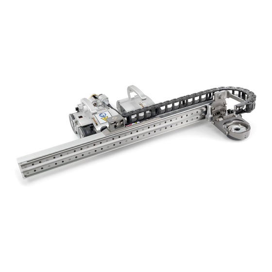
Page 60: Raster Arm Module
(e.g. Kopr Kote®) to the connection pivots of both modules. 5.4. Raster Arm Module The motorized raster arm adds two axis automated scan capabilities to the NAVIC. - Raster arm module Fig. 103 The raster arm can carry many different probes for various types of corrosion scans, including conventional 0°... -
Page 61: Mounting A Raster Arm
5.4.1. Mounting a Raster Arm - Slide onto one swivel mount Fig. 104 TIP: This mounting process can be completed from either side of the crawler. Loosen all four black wing knobs on both modules. Slide the raster arm’s mounting rail onto the dovetail jaws of one of the modules (Fig. -
Page 62: Attaching A Cable Tray
5.4.2. Attaching a Cable Tray - Attaching the cable tray Fig. 106 Attach the cable tray’s magnetic end to the magnetic base on the raster arm. Ensure the four divots are aligned with notches on the magnetic end (Fig. 106) - Press bracket to carriage Fig. -
Page 63: Using The Cable Tray
- Slide bracket attaching to carriage Fig. 108 Slide the cable tray bracket until it locks in place (Fig. 108) TIP: The cable tray can be flipped over and reversed to switch which side of the raster arm the cable tray protrudes. 5.4.3. - Page 64 - Route cabling and close flaps Fig. 110 Route all hoses and cables into the cable tray. Clip the flaps to trap the cables in the cable tray (Fig. 110) TIP: Cable routing can be made more convenient. Removal of several flaps every few inches can ease the cable routing process.
-
Page 65: Raster Arm Cable Setup
5.4.4. Raster Arm Cable Setup - Raster arm cable routing Fig. 111 Plug the supplied raster arm cable into the raster arm’s connector located on the raster arm encoder housing. Pinch the cable into (Fig. 111) the first cable bracket on the side of the raster arm encoder housing. CAUTION! Do not disconnect under load. -
Page 66: Mounting Probe Holders
Route the cable through the adjustable clips on the raster arm (Fig. 112) These clips slide along the raster arm allowing the raster arm cable to be positioned as required. TIP: Do not tighten or loosen the clip screws. These clip screws have been specially torqued by the manufacturer to allow for friction movement. -
Page 67: Probe Holder Attachments
5.5. Probe Holder Attachments 5.5.1. HydroFORM™ Probe Holder Designed to function with the Olympus HydroForm™ scanner . To utilize this probe holder, follow these steps: (not provided) - Attach probe holder - Arm adjustment - Lift and pull latch Fig. 114 Fig. -
Page 68: Probe Holder Setup
5.5.2.1 Probe Holder Setup - Mount probe holder to carrier - Vertical adjustment Fig. 118 Fig. 119 Loosen the probe holder adjustment knob and mount the (Fig. 118) heavy duty vertical probe holder’s dovetail jaw to the carrier. The vertical adjustment knob allows the heavy duty (Fig. -
Page 69: Probe Holder Vertical Adjustment
- Align probe with yoke - Tighten knob and screw Fig. 122 Fig. 123 Align the middle of the wedge with the centre of the yoke (Fig. 122). Tighten both the probe holder adjustment knob and the arm clamp screw while ensuring the wedge remains centred with the (Fig. -
Page 70: Probe Holder Left/Right Conversion
5.5.2.3 Probe Holder Left/Right Conversion - Remove yoke - Orient to opposite side Fig. 126 Fig. 127 Using the supplied 3 mm driver, unscrew the yoke (Fig. 126). Position the yoke and arms to the opposite side of the probe holder (Fig. -
Page 71: Probe Holder 90° Adjustment
Position the pivot buttons to the inside of the probe holder arms (Fig. 130) Place the probe holder arms on the yoke and tighten the arm clamp screw and probe holder adjustment knob (Fig. 131) Screw the yoke to the probe holder (Fig. -
Page 72: Corrosion Thickness Probe Holder
5.5.3. Corrosion Thickness Probe Holder Follow these steps when using the corrosion thickness probe holder with a raster arm. - Cable clip - Loosen knob - Remove bracket Fig. 134 Fig. 135 Fig. 136 The supplied cable clip is offered as a means of cable (Fig. -
Page 73: Two Probe Raster Arm
5.5.4. Two Probe Raster Arm - Raster arm with 2 probe holders Fig. 139 To mount 2 probe holders to the raster arm, follow these steps: NOTE: Do not mount in excess of 2 probe holders to the front of the raster arm. - Remove pivot nose - Install (male) pivot nose Fig. -
Page 74: Pivoting The Raster Arm
Mount a frame bar to the pivot nose (Fig. 142) Follow the steps to mount and (see “Probe Holder Setup” on page 80) setup the vertical probe holders (Fig. 143) 5.5.5. Pivoting the Raster Arm - Pivot raster arm - Parallel with scan surface Fig. -
Page 75: Raster Arm Cable
5.5.7. Raster Arm Cable The raster arm cable connects the raster arm module to the umbilical. The cable provides the 36 VDC and network connections to the raster arm module as well as transmits the raster arm encoder signals to the umbilical. -
Page 76: Battery Powered Optical Guide
Class 1M laser product. - Optical guide Fig. 149 The battery powered optical guide provides a reference point useful for a aligning the NAVIC too a given path . The battery powered optical (i.e. a weld) guide may be installed and setup as follows: Loosen the optical guide knob. -
Page 77: Power Supply
5.7. Power Supply - Power supply Fig. 152 The NAVIC power supply converts power from a 90-270 VAC, 45-65Hz, 5A power source to 36VDC, 11.1A. A start/stop safety circuit and physical ON and OFF push-buttons are integrated into the supply. -
Page 78: Power Supply Cable
WARNING! There are no user serviceable components inside the power supply. Dangerous voltages can be present inside the case. Do NOT open. Return to manufacturer for repair. Only use the power supply with a properly grounded source. The safety of the power supply relies on the provision of a proper ground connection. -
Page 79: Umbilical
- Umbilical Fig. 154 The umbilical is the backbone of the NAVIC system. It provides all power, network distribution as well as encoder signal transmission. Circuitry is incorporated into the umbilical to protect or isolate all signals. The umbilical provides separation between the user’s instrument, power supply and the crawler. - Page 80 (Fig. 155-5) emergency off button to the entire system. When pressed, all power to the NAVIC system will disengage. To restore system power, it is necessary to press the green power button located on the power supply - Emergency off Fig.
- Page 81 umbilical breakout (Fig. 156-1) The motorized left and right modules connect to any of the 8-pin Lemo ® ► receptacles on the crawler umbilical breakout (Fig. 155) The module connected to the ► Y-ENC 8-pin Lemo will transmit ® encoder signals through the umbilical as the 2 encoder axis.
-
Page 82: Controller Cable
NOT be utilized. Use of a damaged cable may be a safety hazard and could also put other system components at risk. 5.11. Encoder Cable The encoder cable connects the NAVIC system to the user’s instrument. This cable allows transmission of necessary two axis position signals from the NAVIC system to the instrument. -
Page 83: Vertical Probe Holder
5.12. Vertical Probe Holder A Latch B Probe Holder Adjustment Knob C Vertical Adjustment Knob D Pivot Buttons Probe Holder Arms Yoke G Probe Holder Arm Adjustment Knob H Transverse Adjustment Screw Frame Bar - Vertical probe holder Fig. 162 5.12.1. -
Page 84: Probe Holder Vertical Adjustment
To mount a UT wedge in the probe holder, follow these steps: - Adjust inner arm - Adjust outer arm - Tighten arm knob Fig. 166 Fig. 167 Fig. 168 Position the wedge on the inner probe holder arm (Fig. 166) TIP: The probe holder yoke can accommodate many different probe and wedge sizes of varying widths. -
Page 85: Probe Holder Transverse Adjustment
Ensure the probe holder is in the latched, upper position. Lift the probe holder until the latch is fully exposed and snaps out to lock (Fig. 169). Loosen the vertical adjustment knob and slide the probe holder down until the wedge is approximately 6 mm above inspection surface. -
Page 86: Probe Holder Longitudinal Adjustment
Ensure the probe holder is in latched, upper position (Fig. 169). Using the supplied 3 mm hex driver loosen the transverse adjustment screw and rotate the yoke about the vertical shaft achieving the (Fig. 173) desired angle. Tighten the transverse adjustment screw (Fig. -
Page 87: Probe Holder Left/Right Conversion
5.12.5. Probe Holder Left/Right Conversion To reverse the probe holder, follow these steps: NOTE: To perform this operation the 1.5 mm hex wrench (Fig. 4) is required. - Unscrew yoke pivot screw - Remove probe holder arms Fig. 179 Fig. 180 Ensure the probe holder is in latched, upper position (Fig. - Page 88 - Screw yoke to opposite side - Lower 90° stop post Fig. 183 Fig. 184 Mount the yoke to the opposite side of the base using the supplied 3 mm hex driver (Fig. 183) TIP: Keep the yoke level with the base as to ensure no conflicts with the plunger/set screw attached to the yoke.
-
Page 89: Slip Joint Probe Holder
5.13. Slip Joint Probe Holder A Frame Bar B Probe Holder Adjustment Knob C Latch D Swing Arm Knob E Yoke Probe Holder Arm Adjustment Knob G Probe Holder Arm H Arm Clamp Screw Pivot Buttons - Slip Joint Probe Holder Fig. - Page 90 Use swing arm knob to position the swing arm (Fig. 190). TIP: The swing arm is typically used to adjust TOFD center to center distance relative to the phased array probes on a four probe configuration. Using the supplied 3/8 in wrench , place the pivot buttons (Fig.
-
Page 91: Probe Holder Adjustment
5.13.2. Probe Holder Adjustment To adjust the probe holder, follow these steps: 6 mm approx. - Lift to Latched position - Lower to scanning surface Fig. 195 Fig. 196 Ensure probe holder is in latched, upper position . If the probe (Fig. - Page 92 When configured correctly, these Light 1 kg 2 lb settings exert the indicated spring Medium 2 kg 4 lb force on the Probe. Heavy 3 kg 6 lb To adjust the probe holder’s force, follow these steps: NOTE: Do not perform this operation on scanning surface. - Unlatched position - Lift slightly and press Latch Fig.
-
Page 93: Slip Joint Probe Holder Left/Right Conversion
Gently apply pressure on the long leg of the 3 mm hex wrench until the force Medium Medium Heavy Heavy adjustment marker lines up with the desired spring Light Light tension. While keeping the markers in line, tighten the force adjustment screw Force Adj. - Page 94 Flip the yoke 180° and reverse the probe holder arms (Fig. 206) Place the pivot buttons on the inside of the probe holder arms (Fig. 207) using a 3/8 in wrench . Slide the arms onto the yoke and tighten the (Fig.
-
Page 95: Low Profile Probe Holder Frame
- Low profile probe holder frame Fig. 211 The low profile frame adds weld scanning capability to the NAVIC motorized scanner. This frame can utilize (4) slip joint probe holders (2 Phased Array and 2 TOFD, typically). The low profile design of this frame allows for scanning on diameters where radial clearance is limited. - Page 96 Affix the probe holders to the low profile probe (with attached wedges) holder frame. On the frame bar, place the secondary probe holders at the front and the primary probe holders at the rear (Fig. 212-2) (Fig. 212-1). TIP: Due to their larger size, scan results are generally improved when pulling or dragging phased array wedges.
- Page 97 Loosen the rear rotational adjustment knob to lower the front frame bar of the low profile frame towards the inspection surface (Fig. 214) - Align probe holder tangent with scan surface Fig. 215 Loosen the front rotational adjustment knob to align the frame (Fig.
-
Page 98: Probe Holder Frame
5.15. Probe Holder Frame The probe holder frame adds weld scanning capability to the NAVIC motorized scanner. This frame uses vertical probe holders. Additional frame components allow up to eight probes to be used (contact Jireh Industries Ltd. on page 131) - Probe holder frame Fig. - Page 99 Affix the probe holders to the probe holder frame. (with attached wedges) Place the secondary probe holder at the front of the frame (Fig. 218-1) place the primary probe holders at the rear of the frame bar (Fig. 218-2). TIP: Due to their larger size, scan results are generally improved when pulling or dragging phased array wedges.
- Page 100 towards the inspection surface .Ensure gap is no (Fig. 220) (Fig. 220-B) smaller than gap (Fig. 220-A) - Set front rotational adjustment knob Fig. 221 Loosen the front rotational adjustment knob to lower the weld (Fig. 221) frame towards the inspection surface while ensuring gap is no (Fig.
-
Page 101: Pivoting Probe Holder Frame
5.16. Pivoting Probe Holder Frame The pivoting probe holder frame utilizes vertical probe holders. The NAVIC can guide as many as 6 probes in the longitudinal direction. - Pivoting Probe Holder Frame Fig. 223 NOTE: A minimum OD of 305 mm (12 in) is required for longitudinal scanning. -
Page 102: Mounting A Pivoting Probe Holder Frame
5.16.1. Mounting a Pivoting Probe Holder Frame Attach the wedges that are to be used with the probe holders (see Probe Holder Setup on page 74 for additional details). - Connect frame to right drive module Fig. 224 Affix the probe holders to the probe holder frame. -
Page 103: Pivoting Probe Holder Frame Setup
5.16.2. Pivoting Probe Holder Frame Setup 5.16.2.1 Longitudinal Scanning To prepare the pivoting probe holder frame for longitudinal scanning, follow these steps: - Loosen pivot wing knobs Fig. 225 NOTE: The swivel mount must be in a horizontal position during longitudinal scanning (see “Swivel Mount”... -
Page 104: Circumferential Scanning
The pivoting probe holder frame may be configured to allow scanning of flanges and the like. The following steps explain setup of this configuration: - Configure assembly and mount to NAVIC Fig. 228 CX0098 Rev 07.5 PAGE 95 of 131... - Page 105 . Ensure proper placement of the frame bar with (Fig. 228) attached mounting point in relation to the NAVIC. TIP: When the scanning surface is circumferential, only one frame bar with two probes can be used. - Lift frame bar to avoid interference Fig.
- Page 106 - Align frame bar with flange scan surface Fig. 231 Loosen the pivot wing knob and align the frame bar parallel with the scan surface (Fig. 231) CX0098 Rev 07.5 PAGE 97 of 131...
-
Page 107: Optical Guide Pivot Mount
5.16.3. Optical Guide Pivot Mount - Correct probe holder longitudinal adjustment Fig. 232 An optional mounting point for the optical guide (see “Battery Powered Optical is available. To install the pivot mount, see these following Guide” on page 67) instructions: Remove the dovetail bar pivot from one of the sets of frame bars . -
Page 108: Cable Management
5.17. Cable Management The zipper tube is offered in a variety of lengths and provides a means of bundling and protecting cables and hoses that connect to the scanner. 5.17.1. Mounting a Zipper Tube To attach a zipper tube for cable management, follow these steps: - Align with umbilical - Tighten wing knob Fig. -
Page 109: Clamp Setup
- Zip opposite end - Flexible routing Fig. 237 Fig. 238 Once the cable is placed the entire length of tube, bring the zipper from the opposite end to meet at any point in the middle. When necessary, the two zippers may be opened to allow any cables to be routed out of the tube. -
Page 110: Backpack
5.18. Backpack The NAVIC backpack allows the crawler to carry various accessories. To install the backpack, see the following steps: NOTE: The backpack is only compatible with NAVIC crawlers manufactured after the spring of 2015. - Pivot and insert dovetail nut - Tighten screws Fig. -
Page 111: Preamp Bracket
5.19. Preamp Bracket The preamp bracket mounts to any dovetail groove to hold a preamp. Compatible with most standard preamps, use the adjustable screw mounting channel on the bottom of the bracket to attach a preamp. The preamp bracket may also be ordered with velcro straps which are used to hold the preamp. -
Page 112: Maintenance
Chapter 6 MAINTENANCE 6.1. Safety Precautions Before Maintenance WARNING! ELECTRICAL SHOCK HAZARD. Disconnect the power supply when servicing the equipment. The power supply is powered even when the E-Stop push-button is latched in the off position. WARNING! MAGNETIC MATERIAL. The wheels of the crawler produce an extremely strong magnetic field which may cause failure or permanent damage to items such as watches, memory devices,... - Page 113 The NAVIC system must be maintained according to the following schedule. MAINTENANCE ITEM FREQUENCY Inspect safety apparatus This includes: ● All components of tether system. Replace damaged components as necessary. ● Lifting sling on crawler. If the lifting sling shows signs of...
-
Page 114: Troubleshooting
Chapter 7 TROUBLESHOOTING 7.1. Startup Issues Two messages are possible in the event of a startup issue: Joystick Off Center or Checking Network. 7.1.1. Joystick Off Center Left Joystick off Center and Will be Disabled. - Joystick off centre screen Fig. -
Page 115: Startup Override
During startup, the system initializes the communications to all the devices on the network. If the network communication fails for any reason, the Checking Network message will appear and remain on screen. Likely causes of this failure: No devices connected to the network. A problem with one of the devices. -
Page 116: Scan Devices
7.2.1. Scan Devices This utility scans the system network for devices. All possible device addresses and speeds are scanned. As devices are found, the address of the device and speed are displayed. When the scanning is complete, power to the system must be cycled. -
Page 117: Reset Parameters
7.2.2. Reset Parameters If the system parameters become corrupt or a change is made that prevents the system from functioning properly. All system parameters may be restored to their factory settings by selecting this option. When pressing the Reset Params button, the changes occur immediately. Power will need to be cycled for the reset to be complete. -
Page 118: Additional Issues
Umbilical cable not Check umbilical cable connections at properly connected. both ends. Ensure connectors are dry, clean and connector pins are not bent. NAVIC system not Start the NAVIC system. (see “System started. Startup” on page 22) Damaged components in Contact manufacturer. -
Page 119: Retrieval Of A Stranded Crawler
(i.e. a mechanism or person must be continuously taking up the slack in the tether) Should the NAVIC crawler become inoperative while out of reach, attempt first, the solutions offered in this manual (see “Troubleshooting” on page 105) If troubleshooting does not rectify the issue, it may be necessary to retrieve the crawler manually. -
Page 120: Service And Repair
In accordance with European Directive on Waste Electrical and Electronic Equipment (WEEE), this symbol indicated that the product must not be disposed of as unsorted municipal waste, but should be collected separately. Refer to Jireh Industries for return and/or collection systems available in your country. CX0098 Rev 07.5... -
Page 121: Spare Parts
Chapter 9 SPARE PARTS To order accessories or replacement parts for your NAVIC system. (contact Jireh Industries Ltd. on page 131) NOTE: These drawings are for parts order. This is not a list of kit contents. 9.1. Crawler BOM ID Part #... -
Page 122: Kit Components
9.2. Kit Components BOM ID Part # Description CXA011 Navic Case DMA001 Handheld Controller UMA015-05 Umbilical (10 m, 15 m, 30 m available) UMA017-06 Controller Cable UMA016-X-05 Encoder Cable (see Encoder Connector Type) AAS061 Installation/Removal Mat EA480 Flat Driver CXA009... -
Page 123: Raster Arm Module
9.3. Raster Arm Module BOM ID Part # Description CWS007 Raster Arm Pivot Nose (female) CWS019 Raster Arm Pivot Nose (male) CWS011 Cable Management Clip MD049-004 SHCS, M3x0.5 x 4 mm, SST See Mounting Rail See Base Raster Arm See Cable Tray UMA020-0.84 Raster Arm Cable - Raster arm parts... -
Page 124: Base Raster Arm
9.3.2. Base Raster Arm Part # Length CWA006-1160 1160 mm (45 in) CWA006-0900 900 mm (35 in) CWA006-0600 600 mm (24 in) CWA006-0300 300 mm (12 in) - Raster arm cable trays Fig. 257 9.3.3. Cable Tray Part # Length CWS018-1160 1160 mm (45 in) -
Page 125: Cable Tray Parts
9.3.3.1 Cable Tray Parts BOM ID Part # Description See Cable Carrier MD074-008 BHCS, M5x0.8 x 8 mm, SST CWS014 Carriage Bracket CWS015 Cable Tray Bracket CWS016 Magnetic Base CWS017 Magnetic End - Cable tray parts Fig. 259 9.3.3.2 Cable carrier Part # Length GA048... -
Page 126: Corrosion Thickness Probe Holder
9.4. Corrosion Thickness Probe Holder ⌀ BOM ID Part # Description PH0178 Corrosion Thickness Probe Holder Slider MA264 Screw, M8x12 Dog Point Set, SST 5.5x4.3 MD049-012 SHCS, M3x0.5 X 12 , SST BG0091 Cable Clip PH0181 Mounting Bracket - Corrosion thickness probe holder parts Fig. -
Page 127: Hydroform™ Probe Holder
9.5. HydroFORM™ Probe Holder BOM ID Part # Description PH0011-X Pivot Button Style (see Pivot Button Style) MD074-020 Arm Clamp Screw, BHCS, M5x0.8 x 20 mm , SST PH0157 HydroFORM™ Probe Holder Arm EA154 Probe Holder Arm Adjustment Knob - HydroFORM™ probe holder parts Fig. -
Page 128: Probe Holder Frame
9.6. Probe Holder Frame BOM ID Part # Description CX0125 Knob, M4 x 16 CXS043 Vertical Probe Holder Side Arm, Left CXS072-L Arm Mount Block, Left CX0126 Knob, M4 x 0.7 x 11.5 CXS072-R Arm Mount Block, Right CXS042 Vertical Probe Holder Side Arm, Right BG0038-X Frame Bar (see Frame Bar) -
Page 129: Low Profile Probe Holder Frame
Low Profile Probe Holder Frame 9.7. BOM ID Part # Description CXS023 Low Profile Side Arm CXS072-L Arm Mount Block, Left CX0126 Knob, M4 x 0.7 x 11.5 CXS072-R Arm Mount Block, Right BG0038-X Frame Bar (see Frame Bar) - Low profile probe holder frame parts Fig. -
Page 130: Pivoting Probe Holder Frame
CXS072-L Arm Mount Block, Left CX0126 Knob BG0038-X Frame Bar (see Frame Bar) CXS064 NAVIC Front Spacer Mount CXS055 Frame Bar Pivot CXS059 Optical Guide Pivot Mount CXS072-R Arm Mount Block, Right CXS042 Vertical Probe Holder Side Arm , Right - Pivoting probe holder parts Fig. -
Page 131: Slip Joint Probe Holder Parts
9.9. Slip Joint Probe Holder Parts BOM ID Part # Description PHS022 Slip Joint Probe Holder Subassembly MD050-010 Arm Clamp Screw, SHCS, M4x0.7 X 10 , SST PH0104 Swing Arm Knob PH0100 Swing Arm PH0082 Probe Holder Arm Adjustment Knob See Yoke Style See Arm Style PH0011-X... -
Page 132: Vertical Probe Holder Parts
9.10. Vertical Probe Holder Parts BOM ID Part # Description PHS028 Vertical Probe Holder Subassembly PH0082 Probe Holder Arm Adjustment Knob See Arm Style PH0011-X Pivot Button Style (See Pivot Button Style) See Yoke Style MD050-010 Arm Clamp Screw, SHCS, M4x0.7 X 10 , SST - Vertical probe holder parts Fig. -
Page 133: Heavy Duty Vertical Probe Holder
9.11. Heavy Duty Vertical Probe Holder BOM ID Part # Description MD074-020 Arm Clamp Screw, BHCS, Metric SST PHS049 Heavy Duty Probe Holder Subassembly EA154 Probe Holder Arm Adjustment Knob See Heavy Duty Yoke Style PH0165 Probe Holder Arm PH0011-X Pivot Button Style (See Pivot Button Style) - Heavy duty vertical probe holder parts... -
Page 134: Probe Holder Components
(13.78 BG0038-10 (15.75 NOTE: Additional probe holder pivot button types available. BG0038-25 (9.84 BG0038-30 (11.81 Part # Length Part # Length (contact Jireh Industries Ltd. on page 131) BG0038-15 BG0038-45 (17.72 (5.91 BG0038-20 BG0038-50 (19.69 (7.87 BG0038-35 BG0038-40 (13.78 (15.75 (1.97... -
Page 135: Variable Components
(0.11 Sonatest DAAH PA (0.38 (0.12 (0.09 9.13. Variable Components Conical Head (0.20 Zetec PA/TOFD Internal 9.13.1. Frame Bar Part # Length Part # Length BG0038-05 (1.97 BG0038-10 (3.94 BG0038-15 (5.91 BG0038-20 (7.87 (9.84 (11.81 BG0038-25 BG0038-30 BG0038-35 (13.78 BG0038-40 (15.75 (17.72 (19.69... -
Page 136: Encoder Connector Type
- Encoder connector type Fig. 276 NOTE: Additional encoder connector types available. Length Swing Arm Style Part # Length Swing Arm Style Part # (contact Jireh Industries Ltd. on page 131) PH0069 Long PH0100 Short (1.61 (1.81 9.15. Accessories Part #... -
Page 137: Preamp Bracket
9.15.2. Preamp Bracket Part # Description CES029 Preamp Bracket CES029-V Preamp Bracket with Velcro - Preamp bracket parts Fig. 278 9.15.3. NAVIC Backpack Part # Description CXS077 Backpack with Velcro CXS063 Velcro Strap - NAVIC backpack Fig. 279 PAGE 128 of 131... -
Page 138: Limited Warranty
THREE (3) YEARS from the original date of purchase. If a defect exists, at its option Jireh will (1) repair the product at no charge, using new or refurbished replacement parts, (2) exchange the product with a product that is new... - Page 139 Changes or modifications to this unit or accessories, not expressly approved by the party responsible for compliance could void the user’s authority to operate the equipment. All specifications are subject to change without notice. © 2016 Jireh Industries Ltd. PAGE 130 of 131...
- Page 140 DISTRIBUTOR: MANUFACTURER: Jireh Industries Ltd. 53158 Range Road 224 Ardrossan, Alberta, Canada T8E 2K4 Phone: 780.922.4534 Fax: 780.922.5766 jireh.com CX0098 Rev 07.5 PAGE 131 of 131...
- Page 141 Jireh Industries Ltd. 53158 Range Road 224 Ardrossan, Alberta Canada T8E 2k4 780-922-4534 jireh.com...
Need help?
Do you have a question about the NAVIC and is the answer not in the manual?
Questions and answers