Table of Contents

Related Manuals for Jireh Stix


Summary of Contents for Jireh Stix
- Page 1 BG0100 Rev 03 Magnetic Corrosion Scanner...
- Page 2 SAFETY WARNINGS \ PRECAUTIONS KEEP THIS MANUAL – DO NOT LOSE THIS MANUAL IS PART OF THE STIX AND MUST BE RETAINED FOR THE LIFE OF THE PRODUCT. PASS ON TO SUBSEQUENT OWNERS. Ensure any amendments are incorporated with this document.
-
Page 3: Table Of Contents
1.3.1. Included tools 1.3.2. Maintenance Configuration Chapter 2.1. Standard Configuration Operation Chapter 3.1. Setup of a STIX on a Scanning Surface System Components Chapter 4.1. Corrosion Link 4.2. Non Encoded Corrosion Link 4.2.1. Corrosion link adjustment 4.2.2. Mounting a Frame Bar 4.2.3. - Page 4 4.8. Cable Clips 4.9. Cable Management 4.9.1. Cable Management Dovetail Mount 4.9.2. Cable Management Setup 4.9.3. Clamp Setup Service and Repair Chapter 5.1. Troubleshooting 5.2. Technical Support 5.3. Disposal Spare Parts Chapter 6.1. Corrosion Scanner 6.2. Kit Components 6.2.1. Encoder Connector Type 6.2.2.
- Page 5 PAGE iv of iv...
-
Page 6: Introduction
(4 in) of the corrosion link (see Corrosion link adjustment on page 7) 1.1.3. Operating environment The STIX magnetic scanner is designed for use in an industrial environment that is between -20° C and 50° C (-4° F) (122° F) 1.1.4. -
Page 7: Hardware
(Fig. 2) for all typical operations and - 3/8 in wrench Fig. 3 adjustments of the STIX. The 3/8 in wrench is used to remove and install buttons on the probe holders. (Fig. 3) 1.3.2. Maintenance General cleaning of components is important to keep your system working well. -
Page 8: Configuration
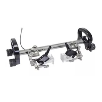
Chapter 2 CONFIGURATION 2.1. Standard Configuration - Standard configuration Fig. 4 BG0100 Rev 03 PAGE 3 of 29... -
Page 9: Operation
Chapter 3 OPERATION 3.1. Setup of a STIX on a Scanning Surface - Frame bar offers protection for PPS encoder Fig. 5 Ensure the frame bar extends past the corrosion link on the encoder (Fig. 6-2) side. This will provide protection to the index encoder connector. The non encoded link can be flush with the frame bar (Fig. - Page 10 - Place scanner on scan surface Fig. 8 Place the STIX on the scanning surface (Fig. 8) TIP: Use caution when placing equipment on the scan surface. The magnetized wheels can cause the assembly to lurch towards the metal suddenly.
-
Page 11: System Components
Chapter 4 SYSTEM COMPONENTS 4.1. Corrosion Link The corrosion link provides braking for (Fig. 9) the system as well as an internal encoder connected to the wheels. A connection plug exists for index encoding. A mounting point for the frame bar is also provided. The corrosion link length can be adjusted to increase scanner diameter range as... -
Page 12: Corrosion Link Adjustment
4.2.1. Corrosion link adjustment To achieve the minimum diameter pipe/tube scan range of 10.2 cm (4 in), the corrosion link and non encoded corrosion link must be adjusted as follows. NOTE: The large yoke of the heavy duty probe holder must be replaced with the standard yoke to allow the carrier to fit under the corrosion links (see Yoke Substitution on page 15). -
Page 13: Mounting A Frame Bar
4.2.2. Mounting a Frame Bar - Loosen wing knobs - Tighten wing knobs Fig. 14 Fig. 15 Ensure the two black wing knobs are loose . Slide the frame bar along the (Fig. 14) dovetail nuts of the corrosion link . -
Page 14: Brake
4.2.5. Brake The red lever located on the both the corrosion link and non encoded corro- sion link provide braking to the system. Press the lever down to activate the brake. TIP: When the brake is engaged and the scanner is moved, this may loosen the wheels from the axle. -
Page 15: Carrier
4.3. Carrier With the use of a leadscrew, the carrier can move along the length of the frame bar. - Loosen the leadscrew clamp knob Fig. 20 Loosen the leadscrew clamp knob to allow movement of the carrier (Fig. 20) along the frame bar. -
Page 16: Index Nuts
4.3.2. Index Nuts - Index nuts Fig. 24 The index nuts located along (Fig. 24) the frame bar offer index positions during scans. The arrow found on the handle of the carrier references the arrow on the corresponding index nut. Align the arrows using the ruler to set the desired spacing. -
Page 17: Heavy Duty Vertical Probe Holder
4.4. Heavy Duty Vertical Probe Holder Latch Probe Holder Arm Adjustment Knob Yoke Probe Holder Arms Pivot Buttons Arm Clamp Screw Probe Holder Adjustment Knob Vertical adjustment Knob - Heavy duty vertical probe holder 4.4.1. Probe Holder Setup Fig. 26 - Mount probe holder to carrier - Vertical adjustment Fig. -
Page 18: Probe Holder Vertical Adjustment
Loosen the probe holder adjustment knob and remove the outer probe holder arm (Fig. 29) Loosen the arm clamp screw (Fig. 30). Place the wedge on the pivot button of the inner probe holder (Fig. 30). - Remove outer arm - Pivot buttons Fig. -
Page 19: Probe Holder Left/Right Conversion
4.4.3. Probe Holder Left/Right Conversion - Remove yoke - Orient to opposite side Fig. 35 Fig. 36 Using the supplied 3 mm driver, unscrew the yoke (Fig. 35). Position the yoke and arms to the opposite side of the probe holder (Fig. -
Page 20: Yoke Substitution
Position the pivot buttons to the inside of the probe holder arms (Fig. 39) Place the probe holder arms on the yoke and tighten the arm clamp screw and probe holder adjustment knob (Fig. 40) Use the supplied 3 mm driver to screw the yoke to the probe holder. -
Page 21: Probe Holder 90° Adjustment
4.4.5. Probe Holder 90° Adjustment Remove the yoke using the supplied 3 mm driver (Fig. 35). Orient the yoke to the front of the probe holder and screw the yoke into the threaded hole provided (Fig. 46) - 90° probe holder positioning Fig. -
Page 22: Index Encoder
4.7. Index Encoder The index encoder is used to provide positional feedback perpendicular to the scan direction of travel. - Loosen and slide post in place - Align and mount post Fig. 49 Fig. 50 To install the index encoder, loosen the clamp screw on the encoder with the supplied 3 mm hex driver (Fig. -
Page 23: Cable Clips
4.8. Cable Clips Clips have been provided to assist with cable management. Simply pinch the clip an and press it into the dovetail groove of the frame bar. - Pinch clip - Route cables Fig. 53 Fig. 54 4.9. Cable Management - Cable management Fig. -
Page 24: Cable Management Dovetail Mount
4.9.1. Cable Management Dovetail Mount To attach the cable management, follow these steps: - Loosen and slide on - Tighten knob Fig. 56 Fig. 57 Loosen the knob on the cable management dovetail mount. Slide the mount onto the dovetail link (Fig. -
Page 25: Clamp Setup
Follow the cable placement zipping the tube closed and closing the cable management cable latch (Fig. 59) - Zip opposite end - Flexibility Fig. 60 Fig. 61 Once the cable is placed the entire length of tube, bring the zipper from the tubes opposite end, meeting at any point in the middle (Fig. -
Page 26: Service And Repair
In accordance with European Directive on Waste Electrical and Electronic Equipment (WEEE), this symbol indicated that the product must not be disposed of as unsorted municipal waste, but should be collected separately. Refer to Jireh Industries for return and/or collection systems available in your country. -
Page 27: Spare Parts
Chapter 6 SPARE PARTS To order accessories or replacement parts for your STIX system. (contact Jireh Industries Ltd. on page i) NOTE: These drawings are for parts order. This is not a list of kit contents. 6.1. Corrosion Scanner BOM ID Part # Description DKS009-S-0.4... -
Page 28: Kit Components
(see Encoder Connector Type) BGA017 Rotix Magnetic Corrosion Scanner Case See Heavy Duty Yoke Style BGS068 Dovetail Mount CES067 Cable Management Mount CES066 Cable Management Clamp See Cable Management Length - STIX kit components Fig. 66 BG0100 Rev 03 PAGE 23 of 29... -
Page 29: Encoder Connector Type
- Encoder connector type Fig. 67 Length Swing Arm Style Part # Length Swing Arm Style Part # NOTE: Additional encoder connector styles available. (contact Jireh Industries Ltd. on page i) PH0069 Long PH0100 Short (1.61 (1.81 6.2.2. Cable Management Length Part #... -
Page 30: Pre-Amp Bracket
6.3.2. Pre-Amp Bracket Part # Description CES029 Pre-Amp Bracket CES029-V Pre-Amp Bracket with Velcro - Pre-amp bracket Fig. 70 6.3.3. HydroFORM™ Cart BOM ID Part # Description CA119 Urethane Molded Wheel Bearing - HydroFORM™ wheel replacement Fig. 71 BG0100 Rev 03 PAGE 25 of 29... -
Page 31: Heavy Duty Vertical Probe Holder
6.4. Heavy Duty Vertical Probe Holder BOM ID Part # Description MD074-020 BHCS, M5 x 0.8 x 20 mm, SST PHS049 Heavy Duty Probe Holder Subassembly EA154 Probe Holder Arm Adjustment Knob See Heavy Duty Yoke Style PH0165 Probe Holder Arm PH0011-X Pivot Button Style (See Pivot Button Style) -
Page 32: Probe Holder Components
Length Part # Length (1.97 (3.94 BG0038-05 Part # NOTE: Additional probe holder pivot button types available. Length BG0038-10 Part # Length (contact Jireh Industries Ltd. on page i) (1.97 (3.94 BG0038-05 BG0038-10 BG0038-15 (5.91 BG0038-20 (7.87 BG0038-15 (5.91 BG0038-20 (7.87... -
Page 33: Limited Warranty
THREE (3) YEARS from the original date of purchase. If a defect exists, at its option Jireh will (1) repair the product at no charge, using new or refurbished replacement parts, (2) exchange the product with a product that is new... - Page 34 Changes or modifications to this unit or accessories, not expressly approved by the party responsible for compliance could void the user’s authority to operate the equipment. All specifications are subject to change without notice. © 2015 Jireh Industries Ltd. BG0100 Rev 03 PAGE 29 of 29...
- Page 35 Jireh Industries Ltd. 53158 Range Road 224 Ardrossan, Alberta Canada T8E 2k4 780-922-4534 jireh-industries.com...
Need help?
Do you have a question about the Stix and is the answer not in the manual?
Questions and answers