Advertisement
Quick Links
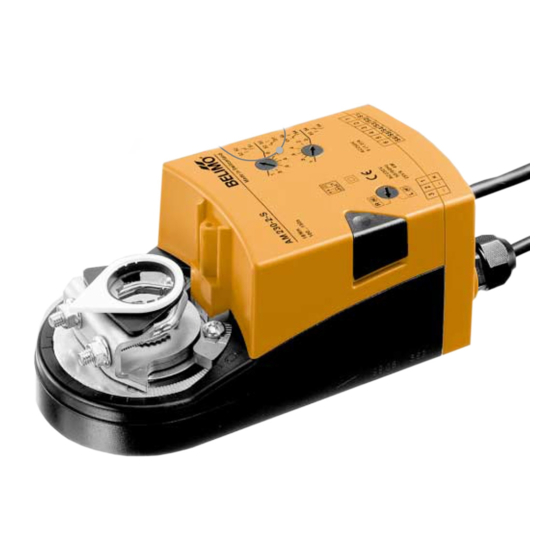
AM230-SR Damper actuator 18 Nm
Wiring diagram
To isolate from the main
Connecting cable
power supply, the system
for power supply
must incorporate a device
which disconnects the
N L1
AC 230 V
phase conductors (with at
least a 3 mm contact gap).
AM230-SR
N L1
Technical data
Nominal voltage
Nominal voltage range
For wire sizing
Power consumption
Connecting cable
Cable glands
(PG11 included)
Control signal Y
Operating range
Function pos. feedback U5
Positioning accuracy
Direction of rotation
(
at Y = 0 V)
Manual operation
Torque
Angle of rotation
Running time
Sound power level
Position indication
Protection class
Degree of protection
Ambient temperature range – 30...+ 50 °C
Non-operating temperature – 40...+ 80 °C
Humidity test
EMC
Low Voltage Directive
Maintenance
Weight
8
Connecting cable for signals
SGA24
SGF24
1
2
3
Y
Vcc
Z
AM230-SR
AC 230 V 50/60 Hz
AC 198...264 V
5 VA (Imax 300 mA @ 2 ms)
running: 4 W, at rest: 3.1 W
power supply: 1 m, 2 x 0.75 mm
signals:
1 m, 4 x 0.75 mm
(direct connection by screw terminals for 2 x 1.5 mm
1 x for motor lead 6...8 mm dia.
1 x for signals lead 8...10 mm dia.
DC 0...10 V @ Ri 47 kΩ
DC 2...10 V
DC 2...10 V @ max. 0.7 mA
± 5%
selected with L / R
at switch position L
resp. R
push button, auto-return
min. 18 Nm
(at rated voltage)
max. 95°
(adjustable 35...100% by mechanical stops)
150 s
max. 45 dB (A)
mechanical
power supply: II
(all insulated)
signal part:
(safety low voltage)
III
IP 54
(bottom cable entry)
to EN 60335-1
CE according to 89/336/EEC, 92/31/EEC, 93/68/EEC
CE according to 73/23/EEC
maintenance-free
1500 g
Y
DC 0...10 V
DC 2...10 V
U 5
Parallel connection
to further AM230-SR.
Power consumption
must be observed.
5
U PP
AM230-SR
2
2
2
wire possible)
Dampers up to approx. 3.6 m
Modulating actuator (AC 230 V)
Control DC 0...10 V
Position feedback DC 2...10 V
Multi-function connection
Application
The type AM230-SR is intended for the
operation of air control dampers in venti-
lation and air-conditioning systems.
Mode of operation
Modulating control is effected by means of
a standard DC 0...10 V control signal.
Product features
Basic positions
When the power supply is switched on for
the first time, i.e. during the initial commis-
sioning or after pressing the pushbutton,
the actuator will run to the basic position.
Basic positions
Pos. reversing switch
L
Y = 0
M
ccw
R
Y = 0
M
cw
The actuator then runs to the position de-
manded by the control signal.
Simple direct mounting on the damper
spindle by universal spindle clamp. An an-
tirotation device is supplied.
Manual operation by self-resetting push-
button when necessary (gearing disen-
gaged while the button is held depressed).
Adjustable angle of rotation with mecha-
nical stops.
High functional reliability (overload-proof)
needs no limit switches, halts automatically
at the end stops.
Connection is either by means of the pre-
fitted leads included with the actuator or
directly by means of screw terminals. In the
case of direct connection the terminal box
will be opened (page 15/16).
Electrical accessories
SA1, SA2
Auxiliary switches, page 17
PA...
Feedback potentiometer, p.18
Mechanical accessories, page 22
ZG-AM
Damper linkage kit
Mounting instructions, page 21/22
Important: Read the notes about the use
and torque requirements of the damper
actuators on page 3.
Dimensions
216
191
B
C
2
Stop left
Stop right
10...20
10...16
46
Advertisement

Summary of Contents for Belimo AM230-SR
- Page 1 Control DC 0...10 V Position feedback DC 2...10 V Multi-function connection Application The type AM230-SR is intended for the operation of air control dampers in venti- lation and air-conditioning systems. Mode of operation Modulating control is effected by means of a standard DC 0...10 V control signal.
- Page 2 Control and monitoring functions AM230-SR Override control With relay contacts With rotary switch Y (DC 0...10 V) from controller Y (DC 0...10 V) from controller Functions Functions 100% 100% Control mode acc. to Y Control mode acc. to Y AM230-SR...


Need help?
Do you have a question about the AM230-SR and is the answer not in the manual?
Questions and answers