Advertisement
Quick Links
Mounting Installation Instructions
LM, NM, AM, GM
Please refer to the appropriate product liter-
ature for detailed installation information.
Reference
• Mounting Methods Guide
• Wiring Guide
• Damper Application Guide
Auxiliary Switches
The ...-S model actuators are equipped with an
adjustable auxiliary switch used to indicate damp-
er position or to interface additional controls or
equipment. Switching positions can be set over
the full 0 to 95° rotation simply by setting
a switch on the actuator.
S2 S3
S2 S3
Switch Rating
Voltage
Resistive load
S1
S1
Inductive load
General Information
Preliminary steps
1.
Belimo actuators with NEMA 1 or NEMA 2
ratings should be mounted indoors in a
dry, relatively clean environment free from
corrosive fumes. If the actuator is mount-
ed outdoors, a protective enclosure must
be used to shield the actuator.
2.
For new construction work, order dampers
with extended shafts. Instruct the install-
ing contractor to allow space for mounting
the Belimo actuator on the shaft.
For replacement of existing gear train actua-
tors, there are two options:
A.
From a performance standpoint, it is
best to mount the actuator directly
onto the damper shaft.
B.
If the damper shaft is not accessible,
mount the non-spring return actuator
with a ZG-NMA or ZG-GMA crankarm
kit, and a mounting bracket (ZG-100,
ZG-101, ZG-103, ZG-104)
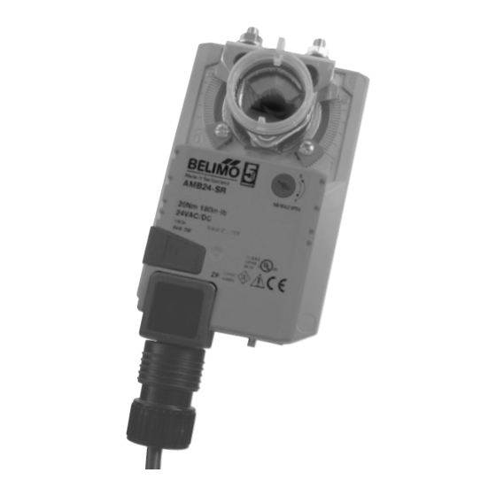
Direction of Rotation Switch
Non-spring return actuators have a reversing
switch on the cover. Switch position indicates
start point. For the non-spring return, with the
switch in position 1, the actuator rotates clock-
wise with a decrease in voltage or current.
With the switch in position 0, the actuator
rotates counterclockwise with a decrease in
voltage or current.
The non-spring return rotates clockwise when the
switch is in the 1 position and power is applied to
wire #2. When power is applied to wire #3 the
actuator rotates counter clockwise.
Rotating the switch to 0 reverses the control logic.
10 VDC
During checkout, the switch position can be tem-
porarily reversed and the actuator will reverse its
direction. This allows the technician a fast and
250 VAC
easy way to check the actuator operation without
3 A
having to switch wires or change settings on the
0.5 A
thermostat.
When the check-out is complete,
make sure the switch is placed back to its
original position.
®
2 VDC
2 VDC
10 VDC
Advertisement

Subscribe to Our Youtube Channel
Related Manuals for Belimo LMB series


Summary of Contents for Belimo LMB series
- Page 1 ® LM, NM, AM, GM General Information Preliminary steps Belimo actuators with NEMA 1 or NEMA 2 ratings should be mounted indoors in a dry, relatively clean environment free from corrosive fumes. If the actuator is mount- ed outdoors, a protective enclosure must be used to shield the actuator.
- Page 2 Installation Instructions ® Quick-Mount Visual Instruction for Mechanical Installation LM Universal Mounting Bracket See next page for standard mounting instructions. 1/4” to 5/8” 5/16” to 9/16” 1.5” 4 to 5 ft-lb LMQB 1/2” to 1.05” 3/8” to 11/16” 1.5” 6 to 7 ft-lb 1/2”...
-
Page 3: Mounting Installation
Mounting Installation ® Reversible Clamp Quick Mount (NM, AM, GM) Center the anti-rotational bracket in the slot. Standard Mounting 5. ① Snap on the reflective position indicator. 1. Turn the damper shaft until the blades are ➁ Adjust end-stops, if required fully closed. - Page 4 Wiring ® On/Off, Floating Point Torque Running Power Power Feedback (based on 4 in-lb per sq. ft) Time Supply Consumption Airside Products GMB24-3 4 (2.0) GMX24-3 4 (2.0) GMX120-3 4 (2.0) AMB24-3 2.5 (0.2) AMB24-3-S 2.5 (0.2) AMX24-3 2.5 (0.2) AMX24-3-T 2.5 (0.2) AMX120-3...
- Page 5 Wiring ® 2 to 10 VDC Torque Running Power Power (based on 4 in-lb per Feedback Time Supply Consumption sq. ft) Airside Products GMB24-SR 4 (2.0) GMX24-SR 4 (2.0) AMB24-SR 2.5 (0.2) AMX24-SR 2.5 (0.2) AMX24-SR-T 2.5 (0.2) AMX120-SR 4 (1.0) NMB24-SR 2 (0.2) NMX24-SR...
- Page 6 Wiring ® Torque Running Power Power Feedback (based on 4 in-lb per sq. ft) Time Supply Consumption Airside Products GMX24-MFT 4.5 (2.0) AMX24-MFT 4 (1.2) AMQX-MFT 12 (1.5) NMX24-MFT 3.5 (1.2) NMQX-MFT 12 (1.5) LMX24-MFT 2 (1.2) LMQX-MFT 12 (1.5) Wiring VDC/4-20 mA Floating Point...
- Page 7 Wiring ® 0 to 135 Ω and 0 to 20 V Phasecut Torque Running Power Power (based on 4 in-lb per Feedback Time Supply Consumption sq. ft) Airside Products GMX24-MFT95 4.5 (2.0) AMX24-MFT95 4 (1.25) NMX24-MFT95 3.5 (1.25) LMX24-MFT95 2 (1.2) GMX24-PC 4.5 (2.0) AMX24-PC...
-
Page 8: Mechanical Features
2. Move the stops (in 2.5° steps) to the desired position and re-tighten the screws. Z-SMA for replacing AM and SM actuators Z-GMA for replacing GM actuators AM/SM 10/08 Subject to change. © Belimo Aircontrols (USA), Inc.
Need help?
Do you have a question about the LMB series and is the answer not in the manual?
Questions and answers