Advertisement
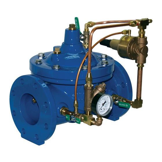
Model ZW205
Pressure Relief / Pressure Sustaining Valve
Globe and Angle Pattern Bodies
1-1/4", 1-1/2", 2", 2-1/2", 3", 4", 6", 8", 10", 12", 14" & 16"
*Contains a weighted average lead content less than 0.25% for wetted surfaces
Installation
Installation / Start-up
NOTE: Flushing of all pipe lines is to be performed to remove all
debris prior to installing valve.
NOTE: When installing a valve, make sure there is adequate space
around the valve for adjustments and servicing.
1. When installing a ZW205, gate valves are recommended on both the
inlet and outlet of the valve for maintenance, allowing for isolation of valve.
2. Position the ZW205 in line matching the direction of flow as indicated on
the valve model tag with the proper direction of flow in the system. Once
attached in-line, double check all fasteners/bolts in the pilot system and
on the main valve are tight and there is no damage prior to pressurizing
the system.
NOTE: Pressure in some applications can be very high so be thor-
ough in checking and inspecting for proper installation and makeup.
3. Zurn Wilkins valves are designed to operate in both the vertical and
horizontal positions. However, it is recommended that ZW205 6" and
larger, be installation in the horizontal position. The horizontal positioning
of the larger valves avoids premature wear due to the mass of the plunger
assembly as well as allows for greater accessibility during annual inspec-
tions, and maintenance.
START-UP
CAUTION: To prevent personnel injury and damage to equipment check
that downstream venting is adequate prior to start-up and test pro-
cedures. All adjustments under pressure should be made slowly
while under flowing conditions.
1. Open the pilot ball valves (2) in the pilot system (see ZW205 sche-
matic).
2. Loosen the pilot adjusting screw jam nut and turn the pilot adjustment
screw clockwise until the spring is completely compressed. Due not
over tighten to prevent damage to the valve.
3. Then slowly open the upstream shutoff valve only enough to slowly
fill the main valve assembly and pilot system. Prior to pressurizing the
valve assembly it is also recommended that a ZPI valve position indica-
tor be installed to aid in verifying proper valve movement.
4. As the valve is filling with water, it is necessary to bleed the main valve
and pilot system of air. To vent air, partially open or loosen the highest
plugs or fittings in the system. The ZPI valve position indicator is a great
location, as it has a test cock at the top to vent air pressure. It may be
necessary to bleed system more than once. After removal of air in the
system tighten all loose fittings. NOTE: If valve is installed vertically, it
will be necessary to loosen some upper cover bolts until you have
vented all the air from the cover chamber.
5. Before setting pilot valve, if valve is equipped with SC1 speed
controls (O or L on ZW205 schematic) it is necessary to back out the
adjusting screw a minimum of 3 turns from closed position.
6. Fully open the outlet gate valve if one is installed.
7. At this point, with the upstream shut-off valve partially open, it is
advisable to flow water through the valve to ensure all air has escaped
from the system. Slowly turn the pilot adjustment screw counterclock-
wise until flow starts to occur. Flow will begin
to occur when the pressure set-point of the pilot decreases below the
inlet pressure.
8. Allow a sufficient amount of water to flow, then turn the adjustment
screw clockwise until flow stops. Fully open the up
!
WARNING: Cancer and Reproductive Harm - www.P65Warnings.ca.gov
!
ADVERTENCIA: Cáncer y daño reproductivo - www.P65Warnings.ca.gov
!
AVERTISSEMENT: Cancer et néfastes sur la reproduction - www.P65Warnings.ca.gov
®
LEAD-FREE*
Troubleshooting
1747 Commerce Way, Paso Robles, CA 93446 Phone:855-663-9876 Fax:805-238-5766
Maintenance Instructions
stream shut-off valve.
10. Once the system has been thoroughly bled of air, set the relief pres-
sure by slowly turning the adjustment screw counterclockwise until water
starts to flow through the ACV. Now the relief valve is set to the current
inlet pressure. Use the table below to set the relief pressure if desired set
point is different than the current inlet pressure. Turn the adjustment screw
clockwise to increase set pressure or counterclockwise to decrease set
pressure. Add or subtract from the current inlet pressure by turning the
adjustment screw the number of turns required to reach the desired set
pressure based on the adjustment table.
Note: The relief valve is designed for quick closing speeds. A small
amount of water will dribble from the valve when the inlet pressure
is as low as 80% of the set pressure during normal operation.
Relief Pilot
Adjustment
Range
150-300
50-200
30-90
10-35
5-15
*Note: Pressure change per turn is approximate. Use a gauge at
the inlet of ACV to set /check relief pressure.
11. To verify proper operation of the ZW205, view the valve during nor-
mal operation and check the valve for relief settings. Adjustments can
be made at anytime.
12. After the pilot system has been adjusted and the valve is properly
operating the main valve opening and closing speed controls (O or L)
can be adjusted as needed.
13. When setting speed controls, turning the adjustment screw into the
speed control will restrict the amount of flow through the the needle valve.
Depending on whether the control is for opening or closing (refer to ZW205
schematic) the control will either slow the opening or closing of the main
valve when the adjustment screw is turned into the speed control. Adjust
as needed and tighten jam nut. In general an opening speed control on a
ZW205 should be at least 3 turns in from the furthest closed position to
prevent high pressure surges upstream.
W
5
3
6
1 1/4"- 4"
L
6"- 8"
OPTIONAL
2
4
2
FLOW
ZW205 SCHEMATIC
STANDARD COMPONENTS
Item
1 Main Valve
2 850XL Isolation Valve
3 SXL "Wye" Type Strainer
4 Pressure Gauge
5 Restriction Fitting
6 Closing Speed Control
7 PV-RLF Pressure Relief Valve
Pressure
Change per Turn
(PSI)*
28.5
23
11.5
2.8
2.5
7
O
Z
C
2
2
F
1
OPTIONAL FEATURES
C 40XL Hydraulic Check w/
Isolation Valve
L SC1 Closing Speed Control
(Standard 1 1/4" - 4")
O SC1 Opening Speed Control
ZURN WILKINS
www.zurn.com
®
1
Advertisement
Table of Contents

Related Manuals for Zurn Wilkins ZW205


Summary of Contents for Zurn Wilkins ZW205
- Page 1 2. Position the ZW205 in line matching the direction of flow as indicated on the valve model tag with the proper direction of flow in the system. Once pressure.
-
Page 2: Troubleshooting
CAUTION: Do not service valve while under pressure. Performing on the cover. Water will flow from the cover as the plunger as- diagnosis checks on the ZW205 when the valve is fully open, high sembly rises, if water continues to flow once fully open then there flow rates and high downstream pressures can occur. -
Page 3: Maintenance Instructions
On larger valves 8” and up, eye bolts and a hoist are recommended due to the weight of these The Zurn Wilkins ZW200 models require minimal maintenance. larger covers. However, it is highly recommended to schedule annual inspec- tions and to have a repair kit on hand before work begins. -
Page 4: Inspection Of Components
9. Slowly open upstream isolation valve to pressurize the system BODY PLUGS and check for any leaks. * RUBBER REPAIR KIT ITEMS † COMPLETE REPAIR KIT ITEMS ‡ SEAT REPAIR KIT ZURN WILKINS ® 1747 Commerce Way, Paso Robles, CA 93446 Phone:855-663-9876 Fax:805-238-5766 www.zurn.com... - Page 5 5. On the other side of the stem place the small washer, Pilot Bell O-ring, Buna Nitrile, NSF Listed o-ring, plunger (with the rubber facing away from the 3x8-16 Jam Hex Nut Relief Pilot Seat spacer), and nut. ZURN WILKINS ® 1747 Commerce Way, Paso Robles, CA 93446 Phone:855-663-9876 Fax:805-238-5766 www.zurn.com...
-
Page 6: Flow Characteristics
Note: If the valve discharges to atmosphere regularly adequate back pressure is very important to prevent damage to valve, throttle discharge from valve with a gate or butterfly valve. ZURN WILKINS ® 1747 Commerce Way, Paso Robles, CA 93446 Phone:855-663-9876 Fax:805-238-5766 www.zurn.com...