Advertisement
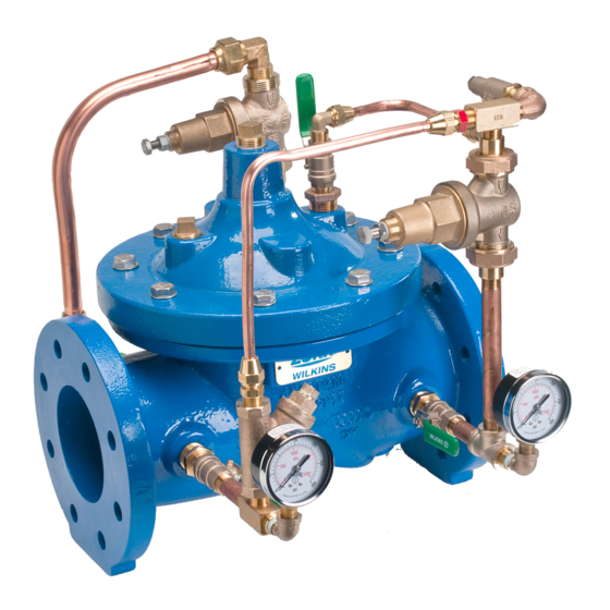
Model ZW209 & ZW209BP LEAD-FREE*
Pressure Reducing Valve Assembly & with Low Flow By-Pass
Globe and Angle Pattern Bodies
1 1/4", 1 1/2", 2", 2-1/2", 3", 4", 6", 8",10", 12", 14" & 16"
*Contains a weighted average lead content less than 0.25% for wetted surfaces
Installation Troubleshooting Maintenance Instructions
Installation / Start-up
NOTE: Flushing of all pipe lines is to be performed to remove all
debris prior to installing valve.
NOTE: If installation is subject to very low flow or potentially static
conditions it is recommended a pressure relief valve (1/2" minimum)
be installed downstream of the pressure reducing valve for additional
system protection.
1. For making adjustments and servicing allow for adequate space around
the valve before installing valve.
2. When installing a ZW209 or ZW209BP, gate valves installed on both inlet
and outlet are recommended for maintenance allowing for isolation of valve.
3. Position the valve in line matching the direction of flow as indicated on
the valve model tag with the proper direction of flow in the system. Once
attached to line, double check all fasteners/bolts in the pilot system and on
main valve are tight and there is no damage prior to pressurizing system.
NOTE: Pressure in some applications can be very high so be thor-
ough in checking and inspecting for proper installation and makeup.
4. Zurn Wilkins valves are designed to operate in both the vertical and
horizontal positions. However, it is recommended that ZW209 6" and
larger, be installated in the horizontal position. The horizontal positioning
of the larger valves avoids premature wear due to the mass of plunger
assemblies as well as allows for greater accessibility during annual inspec-
tions, and maintenance.
C
5
*
3
L
4
2
FLOW
ZW209 SCHEMATIC
STANDARD COMPONENTS
1 Main Valve
2 850MXL Isolation Valve
3 SXL Wye Type Strainer
4 Pressure Gauge
5 Restriction Tube Fitting
6 PRXL PRV (15-150 psi)
7 *PRXL Pressure Reducing
Control By-Pass (ZW209BP only)
START-UP
CAUTION: To prevent personnel injury and damage to equipment
check that downstream venting is adequate prior to start-up and
test procedures. All adjustments under pressure should be
made slowly while under flowing conditions. If the main valve
closes too fast it may cause surging in upstream piping.
1. Open the pilot ball valves (2) in the pilot system (see ZW209 or
ZW209BP schematic).
2. Then slowly open the upstream supply shutoff valve only enough
to fill main valve assembly and pilot system. Prior to pressurizing
!
WARNING: Cancer and Reproductive Harm - www.P65Warnings.ca.gov
!
ADVERTENCIA: Cáncer y daño reproductivo - www.P65Warnings.ca.gov
!
AVERTISSEMENT: Cancer et néfastes sur la reproduction - www.P65Warnings.ca.gov
7
C
6
O
Z
C
2
4
2
4
2
1
OPTIONAL FEATURES
C 40XL Hydraulic Check w/
Isolation Valve
L SC1 Closing Speed Control
O SC1 Opening Speed Control
Z ZPI Valve Position Indicator
6 PV-PRD (20-200 psi)
the valve assembly it is also recommended that a ZPI valve position
indicator be installed to aid in verifying proper valve movement.
3. As the valve is filling with water, it is necessary to bleed the main valve
and pilot system of air. To vent air, partially open or loosen the highest
plugs or fittings in the system. Use caution when loosening plugs. The
ZPI valve position indicator is a great location, as it has a test cock at the
top to vent air pressure. It may be necessary to bleed system more than
once. After removal of air in the system tighten all loose fittings. NOTE:
If valve is installed vertically, it will be necessary to loosen some
upper cover bolts until you have vented all the air from the cover
chamber.
4. Before setting pilot valve, if valve is equipped with SC1 speed
controls (O or L on ZW209 schematic) it is necessary to back out the
adjusting screw a minimum of 3 turns from closed position.
5. At this point with the upstream supply shutoff valve partially open,
slowly open the downstream system shut off valve. Flow will begin to
occur and pressure should build up in valve and eventually stabilize.
6. Next it is advisable to flow water through the valve to ensure all air
has been escaped from system. High flow may be needed to flush all air.
With water flowing through the valve the Zurn Wilkins Pressure Reducing
Valve (PRV) pilot can be set to the desired pressure. To adjust the pilot,
loosen jam nut on adjustment screw and either turn adjustment screw in
(to increase pressure) or out (to decrease pressure). Tighten jam nut on
pilot when the desired setting has been made. Flow at least 5-10 gpm
minimum. Higher flow is better for more accurate setting. If valve has a
low flow bypass, or a parallel installation, you must close a ball valve in
the bypass line and isolate any parallel valves.
7. For ZW209BP the low flow by-pass control must be set 5-10 psi
greater than main Pilot PRV. Isolate the main valve by closing the
downstream pilot ball valve below the pilot. Open the low flow bypass
ball valves. To set the low flow bypass, you only want a trickle of water
flowing. Adjust the bypass PRV to 5 psi higher than the main pilot PRV.
If you cannot determine the flow, then close the downstream ball valve
and then slowly crack the downstream ball valve just until the needle on
the pressure gauge drops a small amount (a downstream valve must be
partially open to allow for a small amount of flow). Now set the bypass
statically 5 psi higher than the main pilot PRV setting. Once the bypass
PRV is set slowly open both ball valves on the bypass and open all 3 ball
valves in the main pilot PRV piping. Tighten the bypass PRV jam nut.
To verify proper operation of ZW209 & ZW209BP slowly close and open
downstream system shut off valve several times to ensure downstream
pressure is stable at set pressure.
8. After pilot system has been adjusted and the valve is properly regulat-
ing the main valve opening and closing speed controls (O or L) can be
adjusted as needed. Start with the opening speed control "O" three turns
from fully closed. Unscrew stem to speed up the valve opening (will help
if downstream pressure drops too far when there is a sudden increase of
demand). If wild pressure fluctuations and chatter occur at low flow, turn
the setting screw in slowly until valve stabilizes. A closing speed control
"L" is not normally used on a pressure reducing valve because a closing
speed control can cause downstream high pressure surges. If present,
start with this wide open by unscrewing the stem completely. Adjust by
turning in to slow the closing speed only as needed, but never more than
three turns from fully closed. Tighten the locknuts on the speed controls
Troubleshooting
The following troubleshooting information in Tables deals strictly with the
ZW209 and ZW209BP valve and pilot systems. It is recommended to
verify that the pilot system is properly functioning before troubleshooting
the main valve. All trouble shooting can be
®
Advertisement
Table of Contents

Related Manuals for Zurn Wilkins ZW209


Summary of Contents for Zurn Wilkins ZW209
- Page 1 (O or L on ZW209 schematic) it is necessary to back out the main valve are tight and there is no damage prior to pressurizing system.
-
Page 2: Troubleshooting
ZW209. If installed, verify the main valve is closed by checking the posi- closed. -
Page 3: Maintenance Instructions
Maintenance Instructions PREVENTATIVE MAINTENANCE 4. With the cover removed the diaphragm assembly can be The Zurn Wilkins ZW200 models require minimal maintenance. removed. To avoid damaging the seat bushing, grab the stem However, it is highly recommended to schedule annual inspec- and lift straight up. -
Page 4: Inspection Of Components
Check” sections for returning valve to proper system operations. BODY BODY PLUGS * RUBBER REPAIR KIT ITEMS † COMPLETE REPAIR KIT ITEMS ‡ SEAT REPAIR KIT ZURN WILKINS ® 1747 Commerce Way, Paso Robles, CA 93446 Phone:855-663-9876 Fax:805-238-5766 www.zurn.com... -
Page 5: Flow Characteristics
150 + 20 = 170 psi. When inlet pressure is below set point, the outlet pressure will be the pressure at the inlet minus the friction loss. ZURN WILKINS ® 1747 Commerce Way, Paso Robles, CA 93446 Phone:855-663-9876 Fax:805-238-5766 www.zurn.com...
Need help?
Do you have a question about the ZW209 and is the answer not in the manual?
Questions and answers