Advertisement
Quick Links
—
Q U I C K S TA R T G U I D E
ATS Annunciator - MODBUS
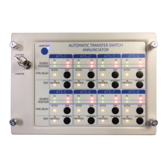
ATS Annunciator monitors and controls up to 8 Automatic Transfer Switches equipped
with the MX150/250 Controller.
Before getting started, have the following tools and information available:
• PC or Laptop with USB
• USB to RS-485 adapter - FTDI Chip USB-RS485-WE-1800-BT or similar.
• ATS Annunciator Tool - PC graphic user interface for ATS Annunciator configuration
• Screw Driver - Phillips #2
Advertisement

Subscribe to Our Youtube Channel
Related Manuals for ABB ATS Annunciator


Summary of Contents for ABB ATS Annunciator
- Page 1 Before getting started, have the following tools and information available: • PC or Laptop with USB • USB to RS-485 adapter - FTDI Chip USB-RS485-WE-1800-BT or similar. • ATS Annunciator Tool - PC graphic user interface for ATS Annunciator configuration • Screw Driver - Phillips #2...
- Page 2 Review Information sections before beginning installation. Information sections follow installation steps — Step 1 - Mount Annunciator 1. Attach both mounting brackets to unit - 2 screws each bracket Brackets may be attached to top and bottom or left and right sides. Orient brackets for wall or flush mount.
- Page 3 — Step 4 - Connect MODBUS Networks 16AWG max. MODBUS networks - See Information: MODBUS Networks • Networks may be either Singly Terminated or Doubly Terminated. • The Annunciator has two separate MODBUSs. ATS MODBUS connects to ATSs - 8 max. PC MODBUS connects a PC to Annunciators - max 32.
- Page 4 Step 6 - Configure Annunciator - ATS Annunciator Tool The ATS Annunciator Tool is graphic user interface that runs on a PC and communicates with the Annunciator via the PC MODBUS connection through an external USB to RS-485 adapter (not furnished).
- Page 5 PC Serial Port Settings > Serial Port - set per the USB to RS-485 adapter instructions; Connect Annunciator Information > Annunciator ID - Select Annunciator to communicate with from list of connected IDs. From PC (Host) MODBUS Port Settings > Annunciator ID - Configure as specified in site installation instructions, if provided.
- Page 6 — LEDs and Operation Power LED KEY SWITCH The MONITOR position allows operation of LEDs only. The CONTROL position allows operation of LEDs and the pushbuttons. Power LED Indicates Annunciator is powered. SOURCE — S1 (Normal) LED (Green) Indicates that the corresponding Transfer Switch has an acceptable Normal source. SOURCE —...
- Page 7 — Information MODBUS Networks Networks may be either Singly Terminated or Doubly Terminated. The Annunciator has two separate MODBUSs. • ATS MODBUS connects to ATSs. - 8 max. • PC MODBUS connects a PC to Annunciators - max 32. PC MODBUS Network - 1 per network Annunciators - max 32 per network ATS MODBUS Network - 1 per Annunciator ATS MODBUS Network - 1 per Annunciator...
- Page 8 Each device on a MODBUS Network must have a unique ID. Non-unique IDs cause communications conflicts and must be resolved. See Troubleshooting. ATS IDs are set in the ATS MODBUS interface. Annunciator IDs are set via the ATS Annunciator Tool (Step 6). — Factory reset...
-
Page 9: Troubleshooting
— Troubleshooting — MODBUS Device Address Conflict Each MODBUS device must be configured with a unique address. Duplicate MODBUS IDs will cause indeterminate errors 1. Check power supply for proper connection to annunciator unit. (Power LED inside unit will be ON if power supply is connected properly). - Page 10 — Notes...
- Page 11 — Notes...
- Page 12 — ABB Zenith Controls, Inc. 305 Gregson Drive Cary, NC 27511 24-hour support: ABB Technical Services +1 (800) 637-1738 © Copyright 2019 ABB. All rights reserved. Specifications subject to change without notice.
Need help?
Do you have a question about the ATS Annunciator and is the answer not in the manual?
Questions and answers