
Summary of Contents for Domino TUFF
- Page 1 MANUALE D'ISTRUZIONE Instruction manual Impastatrice a bracci tuffanti Double arm Mixers mod. TUFF Mod. MANUALE...
- Page 3 INDICE INFORMAZIONI GENERALI 1.1 Premessa pag. 4 1.2 Scopo del manuale pag. 4 1.3 Dati identificativi della macchina pag. 5 1.4 Garanzia pag. 5 INFORMAZIONI TECNICHE 2.1 Descrizione generale della macchina pag. 6 2.2 Dati tecnici pag. 6 2.3 Istruzioni ed avvertenze per l'utilizzatore pag.
-
Page 5: Informazioni Generali
INFORMAZIONI GENERALI PREMESSA Prima di rendere operativa la macchina leggere attentamente le istruzioni contenute nel presente manuale e seguirne attentamente le indicazioni riportate. Conservare il presente manuale e tutte le pubblicazioni allegate in un luogo accessibile e noto a tutti gli operatori e personale addetto alla manutenzione ordinaria;... -
Page 6: Dati Identificativi Della Macchina
1.3 DATI IDENTIFICATIVI DELLA MACCHINA La targa applicata all'impastatrice facilita la sua identificazione. La targa riporta informazioni tecniche, indica il numero di matricola e tutti i dati necessari per l'identificazione della macchina in caso di bisogno di assistenza e/o consultazioni. I dati riportati sono i seguenti: •... -
Page 7: Informazioni Tecniche
1 2.2 DATI TECNICI I dati tecnici e tecnologici delle macchine sono riportati di seguito: DATI TUFF 40 TUFF 50 TUFF 60 TUFF 80 TUFF 100 TUFF 120 TUFF 160 TECNICI... - Page 8 2.3 ISTRUZIONI ED AVVERTENZE PER L'UTILIZZATORE IL COSTRUTTORE DECLINA QUALSIASI RESPONSABILITÀ SE LE NORME DI PREVENZIONE E DI SICUREZZA, RIPORTATE DI SEGUITO, NON SONO OSSERVATE. INOLTRE IL COSTRUTTORE DECLINA QUALSIASI RESPONSABILITÀ PER DANNI CAUSATI DA UN USO IMPROPRIO DELLE TUFFANTI, OPPURE PER QUALSIASI MODIFICA APPLICATA SENZA AUTORIZZAZIONE.
-
Page 9: Dispositivi Di Sicurezza
– DISPOSITIVI DI SICUREZZA 3.1 SIMBOLI UTILIZZATI Alcuni paragrafi di questo manuale sono molto importanti, sia per la sicurezza dell'operatore che per il corretto funzionamento della macchina. Tali paragrafi sono richiamati da alcuni simboli unificati per attirare l'attenzione dell'operatore, quando consulta il manuale. - Page 10 3.4 NORME DI SICUREZZA PER L'UTILIZZO Durante il lavoro: • Si deve lavorare con tutte le protezioni appropriate nella sede giusta ed in perfetta efficienza. • Non introdurre mani o attrezzi nei posti proibiti o dietro le protezioni previste. 3.5 NORME DI SICUREZZA PER LA MANUTENZIONE Durante le operazioni di manutenzione: •...
- Page 11 ISTRUZIONI PER LA MOVIMENTAZIONE ED IL DISIMBALLO 4.1 PREDISPOSIZIONE DEL LOCALE Il locale di installazione della macchina, supponendosi essere destinato alla produzione, cottura compresa, di prodotti da forno deve: • avere aperture in grado di permettere il passaggio delle parti più ingombranti della macchina; •...
-
Page 12: Installazione
4.4 INSTALLAZIONE 1. Quando si installa una macchina, lasciare attorno dello spazio per la movimentazione. 2. Il livellamento della macchina è importante. Assicurarsi che la macchina appoggi correttamente sul pavimento, senza oscillazioni. 3. Per un perfetto livellamento usare i piedini stabilizzatori. 4.5 AVVERTENZE PER L'INSTALLATORE ELETTRICO Assicurarsi che la tensione di linea sia uguale a quella richiesta dalla macchina e che risulta chiaramente indicata nella targhetta di identificazione della macchina... -
Page 13: Avviamento Della Macchina
5.1 AVVIAMENTO DELLA MACCHINA DESCRIZIONE DEL FUNZIONAMENTO DELL’IMPIANTO: Pannello elettrico fig. 3 Nr. 1 Selettore SPEED 1 = 1 velocità 2 = 2 velocità Nr. 2 Pulsante marcia Nr. 3 Pulsante Stop-Emergenza Nr. 4 Interruttore generale • Per azionare la macchina è necessario ruotare il selettore SPEED e assicurarsi che il selettore sia sulla posizione 1 (1ª... -
Page 14: Funzionamento Della Macchina
Controllare che la direzione di rotazione della vasca sia nel verso indicato dalla freccia sulla vasca. Ponendosi di fronte alla macchina, il braccio impastatore destro deve muoversi in senso orario e il sinistro in senso antiorario; la vasca deve ruotare in senso orario. In caso contrario arrestare immediatamente la macchina premendo il pulsante di emergenza e a macchina spenta, staccare la spina di alimentazione dalla presa e invertire i fili nella spina di alimentazione, scambiando il cavo color marrone con quello nero. -
Page 15: Manutenzione
5) Azionando uno dei dispositivi di sicurezza (pulsante stop-emergenza o griglia di protezione) gli organi in movimento si arrestano in brevissimo tempo. fig. 4 - MANUTENZIONE Per una buona e corretta operatività della macchina, si dovranno rispettare le operazioni di manutenzione, previste dal manuale. - Page 16 6.2 OPERAZIONI PERIODICHE a) Controllare il livello dell'olio della vasca porta-ingranaggi; il pignone più basso deve attingere olio per lubrificare gli altri ingranaggi. Per eventuali aggiunte di olio usare solamente: Olio TOTALERG “CERAN CA”. L'olio va completamente sostituito ogni 6.000 ore di lavoro. Il foro di scarico dell'olio si trova sotto la testa porta-utensili impastatori.
- Page 17 • Sostituire le/e cinghia/e con quelle nuove e procedere al tensionamento delle stesse come descritto nel paragrafo 6.2 punto b. • Rimontare il carter di chiusura. 6.4. 2 Sostituzione del motore Manutenzione straordinaria • Togliere le cinghie come spiegato nel paragrafo precedente; •...
- Page 18 – SICUREZZA E IGIENE ALIMENTARE 7.1 PREMESSA L'analisi dei pericoli sotto elencati è basata: • sulla conoscenza delle condizioni normali d'uso della macchina, specificate nel manuale d'uso; • sul presupposto che la macchina è destinata ad un ambiente di lavoro per la produzione, cottura compresa, di prodotti da forno;...
- Page 19 Tutte le parti meccaniche in movimento, quali gli organi di trasmissione del moto, cinghie, catene, ecc. sono state protette per mezzo di: • N° 1 coperchio superiore fissato con viti alla struttura; • N° 1 carter di chiusura sulla parte posteriore della struttura dotato di aperture per l'areazione del motore fissato con viti alla struttura.
- Page 20 - RICAMBI / DIRITTI RISERVATI 8.1 EVENTUALI ORDINI Eventuali ordini di ricambi devono essere fatti direttamente al costruttore e si dovrà dare le seguenti informazioni: • Modello e numero di matricola della macchina; Questi dati sono riportati sulla targa della macchina. •...
-
Page 21: Schema Elettrico
- PARTI DI RICAMBIO Esploso e leggenda 9.1 SCHEMA ELETTRICO... - Page 22 9.2 RICAMBI / ESPLOSO...
- Page 23 9.3 RICAMBI / LEGGENDA DESCRIZIONE DESCRIZIONE RIPARO IN GRIGLIA ALBERO INGRANAGGI VASCA DISTANZIALI BRACCIO DESTRO SUPERIORE FLANGIA RASCHIATORE BRACCI ALBERO ROTAZIONE VASCA CUSCINETTI FLANGIA CINGHIA VASCA CUSCINETTO FLANGIA CUSCINETTO CONICO ANELLI DI TENUTA DISTANZIALE ALBERO FULCRO BRACCI CUSCINETTO CUSCINETTO ALBERO PIGNONE RIDUTTORE VASCA ALBERO PIGNONE ALBERO RIDUTTORE...
- Page 25 INDEX GENERAL INFORMATION 1.1 Premise page 26 1.2 Aim of the instruction manual page 26 1.3 Identification data of the machine page 27 1.4 Warranty page 27 TECHNICAL INFORMATION 2.1 General description of the machine page 28 2.2 Technical data page 28 2.3 Instructions and notices for the operator page 29...
-
Page 27: General Information
GENERAL INFORMATION 1.1 PREMISE Before operating the machine read the instructions contained in the present manual and follow the indications reported carefully. Preserve the present manual and all the attached papers in an accessible place known to all the operators and the personnel assigned to the ordinary maintenance operations. -
Page 28: Identification Data Of The Machine
1.3 IDENTIFICATION DATA OF THE MACHINE The plate applied on the double arm mixer facilitates its identification. The plate gives technical information, indicates the serial number and the other data necessary for the identification of the machine in case of need for assistance and/or advices. The data on the plate are the following: •... -
Page 29: Technical Information
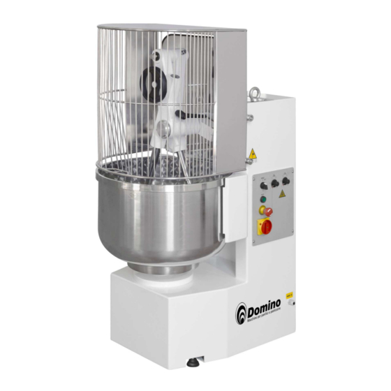
6 - Stainless steel bowl; 7 - Fixing feet. fig. 1 2.2 TECHNICAL DATA The technical data of the double arm mixers are the following: Technical Data TUFF 40 TUFF 50 TUFF 60 TUFF 80 TUFF 100 TUFF 120 TUFF 160... - Page 30 2.3 INSTRUCTIONS AND NOTICES FOR THE OPERATOR THE MANUFACTURER DECLINES ANY RESPONSIBILITY IF THE SAFETY AND PREVENTION NORMS EXPOSED BELOW ARE NOT OBSERVED. THE MANUFACTURER ALSO DECLINES ANY RESPONSIBILITY FOR DAMAGES CAUSED BY THE IMPROPER USE OF THE MIXER OR FOR ANY MODIFICATION MADE WITHOUT AUTHORIZATION.
-
Page 31: Safety Precautions
– SAFETY PRECAUTIONS 3.1 SYMBOLS USED Some paragraphs of the present manual are very important both for the safety of the operator and for the correct running of the machine. Such paragraphs are recalled by some unified symbols to draw the attention of the operator while consulting the manual. - Page 32 3.4 SAFETY RULES FOR THE UTILIZATION While working: • Operate with all the adequate protections at the right plance and in perfect efficiency. • Do not place hands or tools in forbidden places or behind the foreseemn protections. 3.5 SAFETY RULES FOR MAINTENANCE While carrying out maintennace operations: •...
-
Page 33: Unpacking Instructions
4 – INSTRUCTIONS FOR HANDLING AND UNPACKING 4.1 ARRANGEMENT OF THE UTILITY ROOM The utility room for the installation of the machine, supposed to be destinated for the production – including cooking – of bakery products, must: • Have openings to permit the passage of the bulky parts of the machine; •... -
Page 34: Installation
4.4 INSTALLATION 1) When installing the machine, leave sufficient space around it for movement possibilities. 2) The levelling of the machine is important. Make sure that the machines stands correctly on the floor without any oscillations. 3) For a perfect levelling use the stabilizing/adjustment feet. 4.5 WARNINGS FOR THE ELECTRIC INSTALLER Make sure that the tension of the line corresponds to that required by the machine and which is clearly indicated on the identification plate of the machine... - Page 35 5.1 STARTING-UP OF THE MACHINE DESCRIPTION OF THE RUNNING OF THE MACHINE Electrical panel fig. 3 Nr. 1 Selector SPEED 1 = 1 speed 2 = 2 speed Nr. 2 START push button Nr. 3 STOP emergency push button Nr. 4 General switch •...
- Page 36 Control that the rotation direction of the bowl corresponds to the direction of the arrow placed on the bowl. When in front of the machine, the right arm must move clock-wise and the left arm anti clock-wise; the bowl must rotate clock-wise. If the rotations are not correct, immediately stop the machine by pressing the emergency push button and once stopped, release the electric plug from the electric feeding socket and invert the cables of the electric plug by exchanging the brown coloured cable with the black one.
-
Page 37: Maintenance
fig. 4 - MAINTENANCE For a good and proper operating fo the machine, one must respect the maintenance operations recalled in this manual. All maintenance and cleaning works must be carried out with the machine off and after having removed the electric plug from the electric socket. The ordinary maintenance can be carried out by the operator provided that he strictly follows all the instructions in this manual. -
Page 38: Replacement Of Worn Parts
The oil must be completely replaced after every 6000 working hours. The discharging tap of the oil is placed under the head of the machine. b) Control regularly that all the driving belts of the machine are in tension; control the rate of usage and possibly foresee to their replacement which must be made however at the first signal of wear of the rubber. - Page 39 • Remove the driving belts as described in the previous paragraph; • Disconnect the electric cables from the terminal board of the motor, after having removed its cover. Take note of how the cables are connected as the motor has two speeds, and having six cables to disconnect, one could create confusion in connecting them.
- Page 40 – SECURITY AND FOOD HYGIENE 7.1 PREMISE The analysis of the below recalled dangers is based on: • The knowledge of the normal conditions of use of the machine, specified in the manual; • On the presupposition that the machine is destinated to a working place for the production, including cooking, of bakery products;...
- Page 41 All the moving mechanical parts, such as the trasmission means, the driving belts, the chains, etc. have been protected by: • Nr. 1 top cover fixed to the structure by means of screws; • Nr. 1 back cover fixed to the structure by means of screws and equipped with outlets for the circulation of the air.
-
Page 42: Reserved Rights
– SPARE PARTS /RESERVED RIGHTS 8.1 ORDERS The orders of spare parts must be made directly to the manufacturer and the following information must be given: • Model and serial number of the machine; These data are printed on the plate of the machine. •... -
Page 43: Electric Diagram
– SPARE PARTS Expoded view and legend 9.1 ELECTRIC DIAGRAM... -
Page 44: Spare Parts / Exploded View
9.2 SPARE PARTS / EXPLODED VIEW... - Page 45 9.3 SPARE PARTS – LEGEND DESCRIPTION DESCRIPTION GRID PROTECTION GEARS SHAFT BOWL SPACERS UPPER RIGHT ARM FLANGE FOR ARMS SCRAPERS SHAFT FOR BOWL ROTATION BEARINGS FLANGE BOWL BELT BEARING FLANGE TAPERED BEARING SEALING RINGS SPACER SHAFT FOR ARMS PIVOT BEARING BEARING FOR PINION SHAFT BOWL REDUCTION GEAR PINION SHAFT...
Need help?
Do you have a question about the TUFF and is the answer not in the manual?
Questions and answers