Table of Contents
Advertisement
Quick Links
Advertisement
Chapters
Table of Contents

Related Manuals for Diamond Aircraft DA 40 NG


Summary of Contents for Diamond Aircraft DA 40 NG
- Page 2 DA 40 NG AFM Introduction Intentionally left blank. Page 0 - 0a Rev. 3 01-Jul-2014 Doc. # 6.01.15-E...
- Page 3 Before this airplane is operated for the first time, the pilot must familiarize himself with the complete contents of this Airplane Flight Manual. In the event that you have obtained your DIAMOND DA 40 NG second-hand, please let us know your address, so that we can supply you with the publications necessary for the safe operation of your airplane.
- Page 4 Introduction DA 40 NG AFM 0.1 APPROVAL The content of approved chapters is approved by EASA. All other content is approved by DAI under the authority of EASA DOA No. EASA.21J.052 in accordance with Part 21. 0.2 RECORD OF REVISIONS All revisions of this manual, with the exception of •...
- Page 5 DA 40 NG AFM Introduction Rev. Chap- Date of Approval Date Date Reason Page(s) Signature Revision Note of Approval Inserted MÄM 40-415, 40-432, 40-440, 40-448, 40-460, 40-466, 40-447, 40-514, Revision 1 of the AFM Doc. No. OÄM 6.01.15-E is all, except...
- Page 6 Introduction DA 40 NG AFM Rev. Chap- Date of Approval Date Date Reason Page(s) Signature Revision Note of Approval Inserted MÄM 40-777/a, 40-766, 40-765, 40-754, 40-751, 40-742, 40-731, 40-710/a, 40-674, 40-672, 40-662, 40-638, 40-631, 40-632, 40-618/a & OÄM 40-321/b, 40-574,...
- Page 7 DA 40 NG AFM Introduction 0.3 LIST OF EFFECTIVE PAGES Page Date Page Date 15-Jun-2011 01-Jul-2014 0-0a 01-Jul-2014 01-Jul-2014 01-Jul-2014 01-Jul-2014 01-Jul-2014 01-Jul-2014 01-Jul-2014 01-Jul-2014 01-Jul-2014 01-Jul-2014 01-Jul-2014 01-Jul-2014 01-Jul-2014 01-Jul-2014 01-Jul-2014 01-Jul-2014 01-Jul-2014 1-10 01-Jul-2014 01-Jul-2014 1-11 01-Jul-2014 0-10...
- Page 8 Introduction DA 40 NG AFM Page Date Page Date appr. 2-28 01-Jul-2014 appr. 2-1 01-Jul-2014 appr. 2-29 01-Jul-2014 appr. 2-2 01-Jul-2014 appr. 2-30 01-Jul-2014 appr. 2-3 01-Jul-2014 appr. 2-31 01-Jul-2014 appr. 2-4 01-Jul-2014 appr. 2-32 01-Jul-2014 appr. 2-5 01-Jul-2014 appr. 2-33 01-Jul-2014 appr.
- Page 9 DA 40 NG AFM Introduction Page Date Page Date 3-29 01-Jul-2014 01-Jul-2014 3-30 01-Jul-2014 01-Jul-2014 3-31 01-Jul-2014 01-Jul-2014 3-32 01-Jul-2014 01-Jul-2014 3-33 01-Jul-2014 01-Jul-2014 3-34 01-Jul-2014 01-Jul-2014 3-35 01-Jul-2014 01-Jul-2014 3-36 01-Jul-2014 01-Jul-2014 3-37 01-Jul-2014 01-Jul-2014 3-38 01-Jul-2014 3-10 01-Jul-2014...
- Page 10 Introduction DA 40 NG AFM Page Date Page Date 4A-28 01-Jul-2014 4A-1 01-Jul-2014 4A-29 01-Jul-2014 4A-2 01-Jul-2014 4A-30 01-Jul-2014 4A-3 01-Jul-2014 4A-31 01-Jul-2014 4A-4 01-Jul-2014 4A-32 01-Jul-2014 4A-5 01-Jul-2014 4A-33 01-Jul-2014 4A-6 01-Jul-2014 4A-34 01-Jul-2014 4A-7 01-Jul-2014 4A-35 01-Jul-2014 4A-8...
- Page 11 DA 40 NG AFM Introduction Page Date Page Date 4B-28 01-Jul-2014 4B-1 01-Jul-2014 4B-29 01-Jul-2014 4B-2 01-Jul-2014 4B-30 01-Jul-2014 4B-3 01-Jul-2014 4B-4 01-Jul-2014 4B-5 01-Jul-2014 4B-6 01-Jul-2014 4B-7 01-Jul-2014 4B-8 01-Jul-2014 4B-9 01-Jul-2014 4B-10 01-Jul-2014 4B-11 01-Jul-2014 4B-12 01-Jul-2014 4B-13...
- Page 12 Introduction DA 40 NG AFM Page Date Page Date 5-28 01-Jul-2014 01-Jul-2014 5-29 01-Jul-2014 01-Jul-2014 5-30 01-Jul-2014 01-Jul-2014 5-31 01-Jul-2014 01-Jul-2014 5-32 01-Jul-2014 01-Jul-2014 5-33 01-Jul-2014 01-Jul-2014 5-34 01-Jul-2014 01-Jul-2014 5-35 01-Jul-2014 01-Jul-2014 5-36 01-Jul-2014 01-Jul-2014 5-37 01-Jul-2014 5-10 01-Jul-2014...
- Page 13 DA 40 NG AFM Introduction Page Date 01-Jul-2014 01-Jul-2014 01-Jul-2014 01-Jul-2014 01-Jul-2014 01-Jul-2014 01-Jul-2014 01-Jul-2014 01-Jul-2014 6-10 01-Jul-2014 6-11 01-Jul-2014 6-12 01-Jul-2014 6-13 01-Jul-2014 6-14 01-Jul-2014 6-15 01-Jul-2014 6-16 01-Jul-2014 6-17 01-Jul-2014 6-18 01-Jul-2014 6-19 01-Jul-2014 6-20 01-Jul-2014 6-21 01-Jul-2014...
- Page 14 Introduction DA 40 NG AFM Page Date Page Date 7-28 01-Jul-2014 01-Jul-2014 7-29 01-Jul-2014 01-Jul-2014 7-30 01-Jul-2014 01-Jul-2014 7-31 01-Jul-2014 01-Jul-2014 7-32 01-Jul-2014 01-Jul-2014 7-33 01-Jul-2014 01-Jul-2014 7-34 01-Jul-2014 01-Jul-2014 7-35 01-Jul-2014 01-Jul-2014 7-36 01-Jul-2014 01-Jul-2014 7-37 01-Jul-2014 7-10 01-Jul-2014...
- Page 15 DA 40 NG AFM Introduction Page Date Page Date 01-Jul-2014 01-Jul-2014 01-Jul-2014 01-Jul-2014 01-Jul-2014 01-Jul-2014 01-Jul-2014 01-Jul-2014 01-Jul-2014 01-Jul-2014 01-Jul-2014 01-Jul-2014 01-Jul-2014 8-10 01-Jul-2014 8-11 01-Jul-2014 8-12 01-Jul-2014 8-13 01-Jul-2014 8-14 01-Jul-2014 Page 0 - 13 Rev. 3 01-Jul-2014 Doc. # 6.01.15-E...
- Page 16 Introduction DA 40 NG AFM 0.4 TABLE OF CONTENTS Chapter GENERAL (a non-approved chapter) ........1 OPERATING LIMITATIONS (an approved chapter) .
-
Page 17: Table Of Contents
DA 40 NG AFM General CHAPTER 1 GENERAL Page INTRODUCTION ........1-2 CERTIFICATION BASIS . -
Page 18: Introduction
General DA 40 NG AFM 1.1 INTRODUCTION This Airplane Flight Manual has been prepared in order to provide pilots and instructors with all the information required for the safe and efficient operation of the airplane. The Airplane Flight Manual includes all the data which must be made available to the pilot according to the JAR-23 requirement. - Page 19 This Airplane Flight Manual must be kept on board the airplane at all times. Its designated place is the side bag of the forward left seat. CAUTION The DA 40 NG is a single engine airplane. When the operating limitations and maintenance requirements are complied with, it has the high degree of reliability which is required by the certification basis.
-
Page 20: Certification Basis
General DA 40 NG AFM 1.2 CERTIFICATION BASIS This airplane has been type certified in accordance with the procedures established by EASA. The certification basis is JAR-23, published on 11-Mar-1994 and additional requirements as laid down in CRI A-01. 1.3 WARNINGS, CAUTIONS AND NOTES... -
Page 21: Dimensions
DA 40 NG AFM General 1.4 DIMENSIONS NOTE All dimensions shown below are approximate. Overall Dimensions Span 11.63 m 38 ft 2 in Length 8.06 m 26 ft 5 in Height 1.97 m 6 ft 6 in Wing Airfoil Wortmann FX 63-137/20 - W4 Wing area 13.244 m²... - Page 22 General DA 40 NG AFM Horizontal Tail Area 2.34 m 25.2 sq.ft. Elevator area 0.665 m 7.2 sq.ft. Angle of incidence : -3.0° relative to longitudinal axis of airplane Vertical Tail Area 1.60 m² 17.2 sq.ft. Rudder area 0.47 m²...
-
Page 23: Definitions And Abbreviations
DA 40 NG AFM General 1.5 DEFINITIONS AND ABBREVIATIONS (a) Airspeeds CAS: Calibrated Airspeed. Indicated airspeed, corrected for installation and instrument errors. CAS equals TAS at standard atmospheric conditions (ISA) at MSL. IAS: Indicated Airspeed as shown on an airspeed indicator. - Page 24 General DA 40 NG AFM Stalling Speed, or the minimum continuous speed at which the airplane is still controllable in the given configuration. Stalling Speed, or the minimum continuous speed at which the airplane is still controllable in the landing configuration.
- Page 25 DA 40 NG AFM General Pressure Altitude: Altitude above MSL, indicated by a barometric altimeter which is set to 1,013.25 hPa (29.92 inHg). The pressure altitude is the indicated pressure altitude corrected for installation and instrument errors. In this Airplane Flight Manual altimeter instrument errors are regarded as zero.
- Page 26 General DA 40 NG AFM (d) Mass and Balance Center of Gravity, also called 'center of mass'. Imaginary point in which the airplane mass is assumed to be concentrated for mass and balance calculations. Its distance from the Datum Plane is equal to the Center of Gravity Moment Arm.
- Page 27 DA 40 NG AFM General Moment Arm: The horizontal distance from the Datum Plane to the Center of Gravity of a component. Moment: The mass of a component multiplied by its moment arm. Usable Fuel: The quantity of fuel available for flight planning.
- Page 28 General DA 40 NG AFM (f) Designation of the Circuit Breakers on the Instrument Panel ADC: Air Data Computer. ADF: Automatic Direction Finder. AHRS: Attitude and Heading Reference System. ANNUN: Annunciator Panel. AV/CDU FAN: Avionic-, CDU-Cooling Fans. AV. BUS: Avionic Bus.
- Page 29 DA 40 NG AFM General INST.1: Engine Instrument. INST. LT: Instrument Lights. LANDING: Landing Light. MAIN TIE: Bus Interconnection. MASTER CONTROL: Master Control (Avionics Relay). MFD: Multi Function Display. NAV: NAV Receiver. PFD: Primary Flight Display. PITOT: Pitot Heating System.
- Page 30 General DA 40 NG AFM (i) Miscellaneous ACG: Austro Control GmbH (formerly BAZ, Federal Office of Civil Aviation). ATC: Air Traffic Control. CFRP: Carbon Fiber Reinforced Plastic. EASA: European Aviation Safety Agency. GFRP: Glass Fiber Reinforced Plastic. GIA: Garmin Integrated Avionics.
-
Page 31: Units Of Measurement
DA 40 NG AFM General 1.6 UNITS OF MEASUREMENT 1.6.1 CONVERSION FACTORS Dimension SI-Units US Units Conversion Length [mm] millimeter [in] inch [mm] / 25.4 = [in] meter [ft] feet [m] / 0.3048 = [ft] [km] kilometer [NM] nautical mile [km] / 1.852 = [NM]... - Page 32 General DA 40 NG AFM Dimension SI-Units US Units Conversion Intensity of ampère electric current Electric [Ah] ampère-hour charge (battery capacity) Electric volt potential Time [sec] second Page 1 - 16 Rev. 3 01-Jul-2014 Doc. # 6.01.15-E...
-
Page 33: Conversion Chart Liter / Us Gallon
DA 40 NG AFM General 1.6.2 CONVERSION CHART LITER / US GALLON Liter US Gallon US Gallon Liter 15.1 22.7 30.3 37.9 45.4 10.6 53.0 11.9 60.6 13.2 68.1 15.9 75.7 18.5 83.3 21.1 90.9 23.8 98.4 26.4 106.0 29.1 113.6... -
Page 34: Three-View Drawing
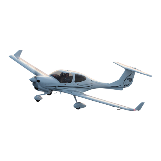
General DA 40 NG AFM 1.7 THREE-VIEW DRAWING Page 1 - 18 Rev. 3 01-Jul-2014 Doc. # 6.01.15-E... -
Page 35: Source Documentation
DA 40 NG AFM General 1.8 SOURCE DOCUMENTATION This section lists documents, manuals and other literature that were used as sources for the Airplane Flight Manual, and indicates the respective publisher. However, only the information given in the Airplane Flight Manual is valid. -
Page 36: Propeller
General DA 40 NG AFM 1.8.2 PROPELLER Address: mt-propeller Airport Straubing Wallmühle D-94348 ATTING GERMANY Phone: +49-9429-9409-0 E-mail: sales@mt-propeller.com Internet: www.mt-propeller.de Documents: E-124, Operation and Installation Manual Hydraulically controlled variable pitch propeller MTV -5, -6, -9, -11, -12, -14, -15, -16, -21, -22, -25 Page 1 - 20 Rev. - Page 37 Operating DA 40 NG AFM Limitations CHAPTER 2 OPERATING LIMITATIONS Page INTRODUCTION ........2-2 AIRSPEED .
-
Page 38: Introduction
Operating DA 40 NG AFM Limitations 2.1 INTRODUCTION Chapter 2 of this Airplane Flight Manual includes operating limitations, instrument markings, and placards necessary for the safe operation of the airplane, its power-plant, standard systems and standard equipment. The limitations included in this Chapter are approved. -
Page 39: Airspeed
Operating DA 40 NG AFM Limitations 2.2 AIRSPEED Airspeed KIAS Remarks up to 1080 kg 101 KIAS (2381 lb) Do not make full or Operating above 1080 kg abrupt control surface maneuvering (2381 lb) to 108 KIAS movement above this... -
Page 40: Airspeed Indicator Markings
Operating DA 40 NG AFM Limitations 2.3 AIRSPEED INDICATOR MARKINGS Marking Significance White arc 60 KIAS - 98 KIAS Operating range with flaps fully extended. Green arc 66 KIAS - 130 KIAS Normal operating range. Yellow arc 130 KIAS - 172 KIAS 'Caution' range - “Only in smooth air”. -
Page 41: Power-Plant Limitations
Operating DA 40 NG AFM Limitations 2.4 POWER-PLANT LIMITATIONS a) Engine manufacturer Austro Engine b) Engine designation E4-A c) RPM limitations (shown as propeller RPM) Maximum take-off (RPM) 2300 RPM max. 5 min Max. continuous power (RPM) : 2100 RPM Max. - Page 42 Operating DA 40 NG AFM Limitations Minimum - 30 °C Maximum 140 °C Normal range 50 °C - 135 °C h) Gearbox temperature Minimum - 30 °C Minimum (full load) 35 °C Maximum 120 °C NOTE A cautionary (yellow) gearbox temperature range is not imposed by the engine manufacturer.
- Page 43 Operating DA 40 NG AFM Limitations k) Fuel pressure (absolute pressure) Minimum 4 bar NOTE The fuel pressure is not indicated; a fuel pressure warning will illuminate on the PFD (if G1000 is installed) or SED (if installed) if the pressure is below the limit.
- Page 44 Operating DA 40 NG AFM Limitations r) Governor mt-Propeller P-853-16 electrical governor s) Oil specification Approved Engine Oil Types SAE Grade SHELL HELIX ULTRA 5W-30 ADDINOL SUPER POWER MV 0537 5W-30 BP Visco 5000 5W-30 5W-30 REPSOL ELITE Common Rail 5W30...
- Page 45 Operating DA 40 NG AFM Limitations CASTROL Edge 0W-40 A3/B4 0W-40 CASTROL Edge Professional A3 0W-40 SHELL HELIX Ultra 0W-40 CAUTION Only engine oils conforming to MB 229.5 specification are approved by Austro Engine GmbH to be used for operation.
- Page 46 Operating DA 40 NG AFM Limitations v) Maximum restart altitude 16,400 ft pressure altitude for immediate restarts 10,000 ft pressure altitude for restarts within 2 minutes EASA Page 2 - 10 Rev. 3 01-Jul-2014 Doc. # 6.01.15-E approved...
-
Page 47: Engine Instrument Markings
Operating DA 40 NG AFM Limitations 2.5 ENGINE INSTRUMENT MARKINGS Engine instrument markings and their color code significance are shown in the table below: Indi- Yellow Green Yellow cation arc/bar arc/bar arc/bar arc/bar arc/bar lower caution normal caution upper prohibited... -
Page 48: Warning, Caution And Status Lights
Operating DA 40 NG AFM Limitations 2.6 WARNING, CAUTION AND STATUS LIGHTS The following tables show the color and significance of the warning, caution and advisory alert lights. There are two variants: G1000 annunciation or SED, MED and ‘White Wire’ annunciator panel. - Page 49 Operating DA 40 NG AFM Limitations Warning Alerts (Red) SED, MED, G1000 Meaning / Cause White Wire installed installed Canopy and/or rear door are/is not closed and DOOR OPEN DOORS locked. Display system is not receiving attitude ATTITUDE reference information from the AHRS;...
- Page 50 Operating DA 40 NG AFM Limitations Color and Significance of the Caution Lights (Amber) Caution Alerts (Amber) SED, MED, G1000 Meaning / Cause White Wire installed installed CAUTION CAUTION One of the cautions below is being indicated. A fault has occurred in the engine ECU A...
- Page 51 Operating DA 40 NG AFM Limitations Color and Significance of the Status Lights (White) Advisory Alerts (White) SED, MED, G1000 Meaning / Cause White Wire installed installed GLOW ON GLOW Engine glow plug active. Fuel transfer from auxiliary to main tank is in...
-
Page 52: Mass (Weight)
Operating DA 40 NG AFM Limitations 2.7 MASS (WEIGHT) Mass (Weight) Value Maximum take-off mass 1280 kg 2822 lb Maximum take-off mass (if MÄM 40-662 is installed) 1310 kg 2888 lb Maximum landing mass 1216 kg 2681 lb if MÄM 40-574 is installed... - Page 53 Operating DA 40 NG AFM Limitations NOTE In some countries the beginning of a flight is defined by starting the engine. In those countries a maximum ramp mass 4 kg (9 lb) above the maximum take-off mass is approved. At the time of lift-off the maximum permitted take-off mass must not be exceeded.
-
Page 54: Center Of Gravity
Operating DA 40 NG AFM Limitations 2.8 CENTER OF GRAVITY Datum Plane The Datum Plane (DP) is a plane which is normal to the airplane’s longitudinal axis and in front of the airplane as seen from the direction of flight. The airplane’s longitudinal axis is parallel with the upper surface of a 600:31 wedge which is placed on top of the rear fuselage in front of the vertical stabilizer. -
Page 55: Approved Maneuvers
Operating DA 40 NG AFM Limitations 2.9 APPROVED MANEUVERS The airplane is to be operated in the Normal Category in accordance with JAR 23. Approved Maneuvers 1) All normal flight maneuvers; 2) Stalling (with the exception of dynamic stalling); and 3) Lazy Eights, Chandelles, as well as steep turns and similar maneuvers, in which an angle of bank of not more than 60°... -
Page 56: Maneuvering Load Factors
Operating DA 40 NG AFM Limitations 2.10 MANEUVERING LOAD FACTORS WARNING The table below shows structural limitations. Exceeding the maximum load factors will lead to an overstressing of the airplane. CAUTION Intentional negative g-maneuvers are not permitted. at v at v... -
Page 57: Operating Altitude
Operating DA 40 NG AFM Limitations 2.11 OPERATING ALTITUDE The maximum operating altitude is 16,400 ft (5,000 m) pressure altitude. 2.12 FLIGHT CREW Minimum crew 1 (one person) Maximum number of occupants : 4 (four persons) EASA Doc. # 6.01.15-E Rev. -
Page 58: Kinds Of Operation
Operating DA 40 NG AFM Limitations 2.13 KINDS OF OPERATION Provided that national operational requirements are met, the following kinds of operation are approved: • Daytime flights according to Visual Flight Rules (VFR) • With the appropriate equipment: night flights according to Visual Flight Rules (NVFR) •... - Page 59 Operating DA 40 NG AFM Limitations For daytime VFR In addition In addition flights for night VFR flights for IFR flights Flight & • Airspeed indicator • Vertical speed • Second airspeed naviga- • Altimeter indicator (VSI) indicator (on PFD tion •...
- Page 60 Operating DA 40 NG AFM Limitations For daytime VFR In addition In addition flights for night VFR flights for IFR flights Engine • Fuel qty. • Ammeter instru- • Oil press. • Voltmeter ments • Oil temp. • Coolant temp.
- Page 61 Operating DA 40 NG AFM Limitations For daytime VFR In addition In addition flights for night VFR flights for IFR flights Lighting • Position lights • Strobe lights (anti collision lights) • Landing light • Instrument lighting • Flood light •...
-
Page 62: Fuel
Operating DA 40 NG AFM Limitations 2.14 FUEL Approved fuel grades: JET A, JET A-1 (ASTM D 1655) TS-1(Russia, GOST 10227-86) TS-1 (Ukraine, GSTU 320.00149943.011-99) RT (Russia, GOST 10227-86) RT (Ukraine, GSTU 320.00149943.007-97) No. 3 Jet Fuel (China, GB 6537-2006) JP-8 (F34) (USA, MIL-DTL-83133G-2010) and blends of the above listed fuel grades. - Page 63 Operating DA 40 NG AFM Limitations CAUTION In case of an unknown or an over dosage of the fuel additives the fuel system must be purged until the dosage is within the permitted limits. NOTE The specified additives are qualified for the operation with the certified fuel grades.
- Page 64 Operating DA 40 NG AFM Limitations Standard Tank Configuration: Total fuel quantity 2 x 15.0 US gal (2 x 56.8 liter) Usable fuel 2 x 14.0 US gal (2 x 53.0 liter) Long Range Tank (if installed) Configuration: Total fuel quantity 2 x 20.5 US gal (2 x 77.6 liter)
-
Page 65: Limitation Placards
DA 40 NG AFM Limitations 2.15 LIMITATION PLACARDS All limitation placards relevant for the base DA 40 NG airplane are shown below. A list of all placards is included in the Airplane Maintenance Manual (Doc. No. 6.02.15), Chapter 11. On the Instrument Panel: THIS AIRPLANE MAY ONLY BE OPERATED IN ACCORDANCE WITH THE AIRPLANE FLIGHT MANUAL IN THE "NORMAL"... - Page 66 Operating DA 40 NG AFM Limitations Next to Each of the Two Fuel Filler Necks: WARNING APPROVED FUEL JET-A1 or see Airplane Flight Manual Next to the Essential Bus Switch: Ess. Bus NOT for normal operation. See AFM. EASA Page 2 - 30 Rev.
- Page 67 Operating DA 40 NG AFM Limitations In the Cowling, on the Door for the Oil Filler Neck: SHELL HELIX ULTRA 5W30 or see Airplane Flight Manual Next to the Flap Selector Switch: max. 110 KIAS max. 98 KIAS On the Fuel Valve:...
- Page 68 Operating DA 40 NG AFM Limitations Next to the Baggage Compartment: Max. 30 kg/ 66 lb Baggage Tube Compartment: Max. 5 kg/ 11 lb Baggage Tray (if OÄM 40-164 installed, extended baggage compartment): EASA Page 2 - 32 Rev. 3 01-Jul-2014 Doc.
- Page 69 Operating DA 40 NG AFM Limitations COCKPIT BAGGAGE BAGGAGE COMPARTMENT EXTENSION MAX. 45 kg [100 lb] MAX. 18 kg [40 lb] ARM: 3.89 m [153.1”] ARM: 4.54 m [178.7”] MAX. BAGGAGE TOTAL (COCKPIT BAGGAGE COMPARTMENT & EXTENSION): 45 kg [100 lb]...
- Page 70 Operating DA 40 NG AFM Limitations On the Left Sidewall, Next to the Instrument Panel: Alternate Static OPEN CLOSED If Alternate Static is open Emergency Window and Cockpit Vent must be closed Beside the Door Locking Device: EMERGENCY EXIT: The keylock must be...
-
Page 71: Other Limitations
Operating DA 40 NG AFM Limitations 2.16 OTHER LIMITATIONS 2.16.1 TEMPERATURE The airplane may only be operated when its temperature prior to operation is not less than -40 °C (-40 °F). With the airplane cold soaked and its temperature below -20 °C (-4 °F) the use of an external pre-heater for the engine and pilot compartment prior to operation is mandatory. -
Page 72: Door Locking Device
Operating DA 40 NG AFM Limitations 2.16.4 DOOR LOCKING DEVICE The canopy and the passenger door must not be key locked during operation of the airplane. 2.16.5 ELECTRONIC EQUIPMENT The use and switching on of electronic equipment other than that which is part of the equipment of the airplane is not permitted, as it could lead to interference with the airplane’s avionics. - Page 73 Emergency DA 40 NG AFM Procedures CHAPTER 3 EMERGENCY PROCEDURES Page INTRODUCTION ........3-3 3.1.1 GENERAL .
- Page 74 Emergency DA 40 NG AFM Procedures SMOKE AND FIRE ........3-33 3.5.1 SMOKE AND FIRE ON GROUND .
-
Page 75: Introduction
Emergency DA 40 NG AFM Procedures 3.1 INTRODUCTION 3.1.1 GENERAL This Chapter contains checklists as well as the description of recommended procedures to be followed in the event of an emergency. Engine failure or other airplane-related emergencies are most unlikely to occur if the prescribed procedures for pre-flight checks and airplane maintenance are followed. -
Page 76: Certain Airspeeds In Emergencies
Emergency DA 40 NG AFM Procedures 3.1.2 CERTAIN AIRSPEEDS IN EMERGENCIES Event KIAS Airspeed for best glide angle (Flaps UP) 88 KIAS Flaps UP 83 KIAS Airspeed for emergency Flaps T/O 78 KIAS landing with engine off Flaps LDG 77 KIAS Page 3 - 4 Rev. -
Page 77: Instrument Indications In Prohibited (Red) Range
Emergency DA 40 NG AFM Procedures 3.2 INSTRUMENT INDICATIONS IN PROHIBITED (RED) RANGE 3.2.1 ENGINE TEMPERATURE Engine coolant temperature is in the upper red range (too high / above 105 °C). Coolant temperatures above the limit value of 105 °C can lead to a total loss of power due to engine failure. - Page 78 Emergency DA 40 NG AFM Procedures During cruise: - Reduce power, or - Increase airspeed, if necessary by initiating a descent. - Check coolant temperature in green range. CAUTION If high coolant temperature is indicated and the COOL LVL (if G1000 is installed) or WATERLEV (if SED is installed)
-
Page 79: Oil Temperature
Emergency DA 40 NG AFM Procedures 3.2.2 OIL TEMPERATURE Engine oil temperature is in the upper red range (too high / above 140 °C). Oil temperatures above the limit value of 140 °C can lead to a total loss of power due to engine failure. - Page 80 Emergency DA 40 NG AFM Procedures CAUTION If high oil temperature is announced and the oil pressure indication is within the green range, it can be assumed that there is no technical defect in the engine oil system and that the above mentioned procedure can decrease the temperature(s).
-
Page 81: Oil Pressure
Emergency DA 40 NG AFM Procedures 3.2.3 OIL PRESSURE Engine oil pressure is in the lower red range (too low / below 0.9 bar). Oil pressures below the limit value of 0.9 bar can lead to a total loss of power due to engine failure. -
Page 82: Gearbox Temperature
Emergency DA 40 NG AFM Procedures 3.2.4 GEARBOX TEMPERATURE Engine gearbox temperature is in the upper red range (too high / above 120 °C). Gearbox temperatures above the limit value of 120 °C can lead to a total loss of power due to engine failure. -
Page 83: L/R Fuel Temperature
Emergency DA 40 NG AFM Procedures 3.2.5 L/R FUEL TEMPERATURE Fuel temperature is in the upper red range (too high / above 60 °C). Fuel temperatures above the limit value of 60 °C can lead to a noticeable reduction of the high pressure pump efficiency. -
Page 84: Fuel Pressure
Emergency DA 40 NG AFM Procedures 3.2.6 FUEL PRESSURE Engine fuel pressure is low. 1. Fuel quantity ......check 2. -
Page 85: Alternator Amps
Emergency DA 40 NG AFM Procedures 3.2.7 ALTERNATOR AMPS Engine alternator output is in the upper red range (too high / above 70 A). This warning is indicated when the consumption of electrical power is too high. Possible reasons are: A fault in wiring or equipment. -
Page 86: Alternator Fail
Emergency DA 40 NG AFM Procedures 3.2.8 ALTERNATOR FAIL Engine alternator has failed. The batteries are the last remaining source of electrical power for about 30 minutes. 1. Circuit breakers ..... . check 2. -
Page 87: Engine Problems
Emergency DA 40 NG AFM Procedures 3.3 ENGINE PROBLEMS 3.3.1 ENGINE PROBLEMS ON GROUND 1. POWER lever ......IDLE 2. -
Page 88: Engine Problems During Take-Off
Emergency DA 40 NG AFM Procedures 3.3.2 ENGINE PROBLEMS DURING TAKE-OFF (a) Take-Off Can Still Be Aborted (Sufficient Runway Length Available) Land Straight Ahead: 1. POWER lever ......IDLE On the Ground: 2. - Page 89 Emergency DA 40 NG AFM Procedures (b) Take-Off Can No Longer Be Aborted 1. Airspeed ......immediate pitch down to avoid...
-
Page 90: Engine Troubleshooting In Flight
Emergency DA 40 NG AFM Procedures 3.3.3 ENGINE TROUBLESHOOTING IN FLIGHT WARNING Control over the flight attitude has priority over attempts to solve the current problem ("first fly the airplane"). 1. Airspeed ......88 KIAS 2. - Page 91 Emergency DA 40 NG AFM Procedures WARNING Do not increase the POWER lever past the propeller speed of 1975 RPM or the setting determined in step 6. An increase of engine power beyond this setting leads into another power loss.
- Page 92 Emergency DA 40 NG AFM Procedures Otherwise: 5. VOTER switch ..... . . switch back to AUTO to retain ECU redundancy If normal engine operation is restored continue flight and land as soon as possible.
-
Page 93: Engine Failure In Flight
Emergency DA 40 NG AFM Procedures 3.3.4 ENGINE FAILURE IN FLIGHT WARNING Control over the flight attitude has priority over attempts to solve the current problem ("first fly the airplane"). NOTE As long as there is no major mechanical engine defect, the propeller will continue to windmill. -
Page 94: Restarting The Engine In Flight
Emergency DA 40 NG AFM Procedures 3.3.5 RESTARTING THE ENGINE IN FLIGHT NOTE With a failed engine the propeller continues to windmill. A stopped propeller indicates a major mechanical engine defect. Starter assisted restart shall not be considered. Maximum restart altitude: 16,400 ft pressure altitude . - Page 95 Emergency DA 40 NG AFM Procedures If Engine Does Not Start: 10. Fuel valve ......EMERGENCY If Engine Does Not Start Adopt Glide Configuration: 11.
-
Page 96: Defective Rpm Regulating System
Emergency DA 40 NG AFM Procedures 3.3.6 DEFECTIVE RPM REGULATING SYSTEM WARNING In case of defective RPM regulating system, reduced engine performance should be anticipated. CAUTION Following a failure of the governor the RPM should be adjusted with the POWER lever. - Page 97 Emergency DA 40 NG AFM Procedures (b) Propeller Overspeed CAUTION Climb performance will be reduced. NOTE The propeller now works like a fixed pitch propeller. RPM is controlled by the engine power setting. Flight to the nearest airfield can be continued with a lower power setting and at a lower airspeed.
- Page 98 Emergency DA 40 NG AFM Procedures If the Problem Does Not Clear: 7. Land on the nearest suitable airfield. If an Increased Climb Rate is Required: 8. Flaps ....... T/O position 9.
- Page 99 Emergency DA 40 NG AFM Procedures (c) Propeller Underspeed 1. POWER lever ......as required If the Problem Does Not Clear 2.
-
Page 100: Fuel Transfer Pump Failure
Emergency DA 40 NG AFM Procedures 3.3.7 FUEL TRANSFER PUMP FAILURE 1. Fuel quantity ......check If Main Tank Fuel Quantity Low: 2. - Page 101 Emergency DA 40 NG AFM Procedures NOTE AUX tank quantity must not be less than 1 US gal and MAIN tank quantity must not be more than 14 US gal. 6. Fuel valve ......NORMAL 7.
-
Page 102: Failures In The Electrical System
Emergency DA 40 NG AFM Procedures 3.4 FAILURES IN THE ELECTRICAL SYSTEM 3.4.1 COMPLETE FAILURE OF THE ELECTRICAL SYSTEM 1. Circuit breakers ..... . check IN 2. -
Page 103: High Current
Emergency DA 40 NG AFM Procedures 3.4.2 HIGH CURRENT If HIGH CURRENT (> 70 A) is indicated on the G1000 (if installed) or SED (if installed): 1. ESSENTIAL BUS ..... ON 2. -
Page 104: Starter Malfunction
Emergency DA 40 NG AFM Procedures 3.4.3 STARTER MALFUNCTION If the starter does not disengage from the engine after starting (Starter engaged warning (STARTER) on the G1000 (if installed) or START on the White Wire annunciator (if installed) illuminates after the engine has started): On Ground: 1. -
Page 105: Smoke And Fire
Emergency DA 40 NG AFM Procedures 3.5 SMOKE AND FIRE 3.5.1 SMOKE AND FIRE ON GROUND (a) Engine Fire When Starting on the Ground 1. Fuel valve ......OFF 2. - Page 106 Emergency DA 40 NG AFM Procedures (b) Electrical Fire with Smoke on the Ground 1. ELECTRIC MASTER ....OFF If the Engine Is Running: 2.
-
Page 107: Smoke And Fire During Take-Off
Emergency DA 40 NG AFM Procedures 3.5.2 SMOKE AND FIRE DURING TAKE-OFF (a) If Take-Off Can Still Be Aborted 1. POWER lever ......IDLE 2. - Page 108 Emergency DA 40 NG AFM Procedures (b) If Take-Off Cannot Be Aborted 1. Cabin heat ......OFF 2.
- Page 109 Emergency DA 40 NG AFM Procedures CAUTION In case of extreme smoke development, the front canopy may be unlatched during flight. This allows it to partially open, in order to improve ventilation. The canopy will remain open in this position. Flight characteristics will not be affected significantly.
-
Page 110: Smoke And Fire In Flight
Emergency DA 40 NG AFM Procedures 3.5.3 SMOKE AND FIRE IN FLIGHT WARNING In the event of smoke or fire, prepare to land the airplane without delay while completing fire suppression and/or smoke evacuation procedures. If it cannot be visually verified that the fire has been completely extinguished, whether the smoke has cleared or not, land immediately. - Page 111 Emergency DA 40 NG AFM Procedures (b) Electrical Fire with Smoke in Flight 1. EMERGENCY switch (if installed) ..ON 2. AVIONIC MASTER ....OFF 3.
-
Page 112: Gliding
Emergency DA 40 NG AFM Procedures 3.6 GLIDING 1. Flaps ....... UP 2. -
Page 113: Emergency Landings
Emergency DA 40 NG AFM Procedures 3.7 EMERGENCY LANDINGS NOTE For all airspeed tables in the following sections apply linear variations between weights. 3.7.1 EMERGENCY LANDING WITH ENGINE OFF CAUTION For emergency landing the adjustable backrests (if installed) must be fixed in the upright position. - Page 114 Emergency DA 40 NG AFM Procedures 9. Approach speed ..... . see table below: up to 940 kg 1000 kg...
-
Page 115: Gear
Emergency DA 40 NG AFM Procedures 3.7.2 LANDING WITH A DEFECTIVE TIRE ON THE MAIN LANDING GEAR CAUTION A defective (e.g. burst) tire is not usually easy to detect. The damage normally occurs during take-off or landing, and is hardly noticeable during fast taxiing. It is only during the roll-out after landing or at lower taxiing speeds that a tendency to swerve occurs. -
Page 116: Landing With Defective Brakes
Emergency DA 40 NG AFM Procedures 3.7.3 LANDING WITH DEFECTIVE BRAKES In general, a landing on grass is recommended in order to reduce the landing run due to the greater rolling resistance. WARNING If sufficient time is remaining, the risk of fire in the event of a collision can be reduced as follows after a safe touch-down: - Fuel valve . -
Page 117: Recovery From An Unintentional Spin
Emergency DA 40 NG AFM Procedures 3.8 RECOVERY FROM AN UNINTENTIONAL SPIN CAUTION Steps 1 to 4 must be carried out immediately and simultaneously. 1. POWER lever ......IDLE 2. -
Page 118: Other Emergencies
Emergency DA 40 NG AFM Procedures 3.9 OTHER EMERGENCIES 3.9.1 ICING Unintentional Flight Into Icing Conditions 1. Leave the icing area (by changing altitude or turning back, in order to reach zones with a higher ambient temperature). 2. Pitot heating ......ON 3. - Page 119 Emergency DA 40 NG AFM Procedures 3.9.2 SUSPICION OF CARBON MONOXIDE CONTAMINATION IN THE CABIN Carbon monoxide (CO) is a gas which is developed during the combustion process. It is poisonous and without smell. Since it occurs however usually together with flue gases, it can be detected.
- Page 120 Emergency DA 40 NG AFM Procedures 3.9.3 UNLOCKED DOORS 1. Airspeed ......reduce immediately 2.
- Page 121 Normal Operating DA 40 NG AFM Procedures CHAPTER 4A NORMAL OPERATING PROCEDURES Page 4A.1 INTRODUCTION ........4A-2 4A.2 AIRSPEEDS FOR NORMAL OPERATING PROCEDURES .
-
Page 122: Introduction
Normal Operating DA 40 NG AFM Procedures 4A.1 INTRODUCTION Chapter 4A contains checklists and describes procedures for the normal operation of the airplane. 4A.2 AIRSPEEDS FOR NORMAL OPERATING PROCEDURES NOTE For all airspeed tables in the following Sections apply linear variations between weights. -
Page 123: Flight Characteristics
(Flaps T/O) 4A.3 FLIGHT CHARACTERISTICS The DA 40 NG is to be flown with "the feet on the pedals“, meaning that coordinated flight in all phases and configurations shall be supported by dedicated use of the rudder and ailerons together. -
Page 124: Checklists For Normal Operating Procedures
Normal Operating DA 40 NG AFM Procedures 4A.5 CHECKLISTS FOR NORMAL OPERATING PROCEDURES 4A.5.1 PRE-FLIGHT INSPECTION I. Cabin Check a) MET, NAV, Mass & CG ....flight planning completed b) Airplane documents . - Page 125 Normal Operating DA 40 NG AFM Procedures n) Position lights, strobe lights (ACL) ..check OFF o) Taxi lights, landing lights ....check OFF p) ELECTRIC MASTER .
- Page 126 Normal Operating DA 40 NG AFM Procedures II. Walk-Around Check, Visual Inspection CAUTION A visual inspection means: examination for damage, cracks, delamination, excessive play, load transmission, correct attachment and general condition. In addition control surfaces should be checked for freedom of movement.
- Page 127 Normal Operating DA 40 NG AFM Procedures 2. Left Wing: a) Entire wing surface ....visual inspection b) Step ....... . visual inspection c) Air intake on lower wing surface .
- Page 128 Normal Operating DA 40 NG AFM Procedures r) Foreign objects in aileron paddle ..visual inspection s) Trim tab ......visual inspection t) Flap and linkage .
- Page 129 Normal Operating DA 40 NG AFM Procedures 5. Fuselage, Right Side: a) Fuselage skin ......visual inspection b) Static source .
- Page 130 Normal Operating DA 40 NG AFM Procedures 7. Right Main Landing Gear: a) Landing gear strut or fairing (if installed) ..visual inspection b) Wear, tread depth of tires ....check c) Tire, wheel, brake .
- Page 131 Normal Operating DA 40 NG AFM Procedures l) Wear, tread depth of tire ....check m) Wheel fairing (if installed) ....visual inspection n) Tow bar .
-
Page 132: 5.2 Before Starting Engine
Normal Operating DA 40 NG AFM Procedures 4A.5.2 BEFORE STARTING ENGINE CAUTION For take off the adjustable backrests (if installed) must be fixed in the upright position. NOTE The pilot must ensure that a passenger sitting on a front seat is instructed in the operation of the adjustable backrest (if installed). - Page 133 Normal Operating DA 40 NG AFM Procedures NOTE A slight downward pressure on the canopy may be required to ease the handle operation. 10. Parking brake ......set 11.
-
Page 134: 5.3 Starting Engine
Normal Operating DA 40 NG AFM Procedures 4A.5.3 STARTING ENGINE CAUTION Before starting the engine and until the engine is shut down, the canopy must be closed and latched in position 1 or 2 (‘cooling gap’) and the door must be closed and latched. - Page 135 Normal Operating DA 40 NG AFM Procedures 1. Strobe lights (ACL) ....ON 2. ENGINE MASTER ....ON 3.
- Page 136 Normal Operating DA 40 NG AFM Procedures 7. Annunciations / STARTER (if G1000 is installed) or START (if White Wire annunciator panel is installed) . . check OFF 8. Annunciations / Oil pressure ... . . check OK 9.
- Page 137 Normal Operating DA 40 NG AFM Procedures 4A.5.4 BEFORE TAXIING 1. AVIONIC MASTER ....ON 2. Power lever ......as required, max. 50% if engine temperature below green range 3.
- Page 138 Normal Operating DA 40 NG AFM Procedures NOTE If the G1000 avionics system and the autopilot GFC 700 are installed, the AFCS automatically conducts a preflight self-test upon initial power application. The preflight test is indicated by a white boxed PFT on the PFD. Upon successful...
- Page 139 Normal Operating DA 40 NG AFM Procedures 4A.5.5 TAXIING 1. Parking brake ......release 2. Brakes ......test 3.
- Page 140 Normal Operating DA 40 NG AFM Procedures 4A.5.6 BEFORE TAKE-OFF CAUTION For take-off the adjustable backrests (if installed) must be fixed in the upright position. 1. Position airplane into wind if possible. 2. Parking brake ......set 3.
- Page 141 Normal Operating DA 40 NG AFM Procedures 11. Fuel valve ......check NORMAL 12.
- Page 142 Normal Operating DA 40 NG AFM Procedures NOTE The engine oil / gearbox temperature has to be in the green range before starting the test sequence. Efficient engine warm up may require higher power settings (max. 50% engine power). Releasing the ECU TEST BUTTON or manipulating the POWER lever before the test sequence is completed will abort the test sequence.
- Page 143 Normal Operating DA 40 NG AFM Procedures 8. ECU A/B FAIL (if G1000 is installed) or ECU A/B (if White Wire annunciator panel is installed) lights ....verify both OFF Test sequence completed.
- Page 144 Normal Operating DA 40 NG AFM Procedures Available Power Check: 1. POWER lever ......MAX for 10 seconds 2.
- Page 145 Normal Operating DA 40 NG AFM Procedures 4A.5.7 TAKE-OFF Normal Take-Off Procedure 1. Transponder ......as required 2.
- Page 146 Normal Operating DA 40 NG AFM Procedures NOTE A spurious activation of the stall warning during take-off in crosswind conditions, operation on unpaved surfaces and gusty conditions may occur. 6. Airspeed for initial climb ....see table below:...
- Page 147 Normal Operating DA 40 NG AFM Procedures 4A.5.8 CLIMB Procedure for Take-Off Climb 1. Flaps ......T/O 2.
- Page 148 Normal Operating DA 40 NG AFM Procedures 4A.5.9 CRUISE 1. Flaps ......UP 2.
- Page 149 Normal Operating DA 40 NG AFM Procedures 4A.5.10 FUEL TRANSFER CAUTION During normal operation fuel is taken from the main tank only. Therefore fuel must be transferred from the auxiliary tank to the main tank by activating the fuel transfer pump. The transfer rate is approximately 60 US gal/h (227 liter/h).
- Page 150 Normal Operating DA 40 NG AFM Procedures 4A.5.11 DESCENT 1. POWER lever ......as required 2. Airspeed ......as required 3.
- Page 151 Normal Operating DA 40 NG AFM Procedures 4A.5.12 APPROACH & LANDING Approach: NOTE If MÄM 40-574 is NOT carried out, a landing with a mass between 1216 kg (2681 lb) and 1280 kg (2822 lb) constitutes an abnormal operating procedure. Refer to Section 4B.7 - LANDING WITH HIGH LANDING MASS.
- Page 152 Normal Operating DA 40 NG AFM Procedures Before Landing: 8. Airspeed ......see table below:...
- Page 153 Normal Operating DA 40 NG AFM Procedures 4A.5.13 GO-AROUND 1. POWER lever ......MAX 2. Airspeed ......72 KIAS 3.
- Page 154 Normal Operating DA 40 NG AFM Procedures 4A.5.14 AFTER LANDING 1. POWER lever ......IDLE 2. Brakes ......as required 3.
- Page 155 Normal Operating DA 40 NG AFM Procedures 4A.5.15 ENGINE SHUT-DOWN 1. Parking brake ......set 2. POWER lever ......up to 10 % load for 1 minute 3.
- Page 156 Normal Operating DA 40 NG AFM Procedures 4A.5.16 POST FLIGHT INSPECTION 1. Record any problem found in flight and during the post-flight check in the log book. 2. Park the airplane. 3. If necessary, moor the airplane. END OF CHECKLIST 4A.5.17 PARKING...
- Page 157 Normal Operating DA 40 NG AFM Procedures 4A.5.18 FLIGHT IN RAIN NOTE Performance deteriorates in rain; this applies particularly to the take-off distance and to the maximum horizontal speed. The effect on the flight characteristics is minimal. Flight through very heavy rain should be avoided because of the associated visibility problems.
- Page 158 Normal Operating DA 40 NG AFM Procedures Anti-microbial life fuel additives may be manually batch-blended into the fuel tanks. In this case introduce the additive while filling the tank after approximately the half tank is filled. Anti-icing fuel additives should not be batch-blended into the fuel tank. The fuel additive should be injected into a stream of fuel.
- Page 159 Normal Operating DA 40 NG AFM Procedures (c) PRIST Hi-Flash Fuel Quantity Fuel Additive *, ** PRIST Hi-Flash (1500 ppm) Liter US gal 13.2 40.2 88.68 58.9 1.99 26.4 80.4 177.37 117.9 3.99 39.6 120.6 266.05 176.8 5.98 * Densities used for calculation: Fuel: 0.804 kg/l, PRIST Hi-Flash: 1.05 kg/l ** Do not batch blend 4A.5.20 FLIGHT AT HIGH ALTITUDE...
- Page 160 Normal Operating DA 40 NG AFM Procedures Intentionally left blank. Page 4A - 40 Rev. 3 01-Jul-2014 Doc. # 6.01.15-E...
- Page 161 Abnormal Operating DA 40 NG AFM Procedures CHAPTER 4B ABNORMAL OPERATING PROCEDURES Page 4B.1 PRECAUTIONARY LANDING ......4B-2 4B.2 INSTRUMENT INDICATIONS OUTSIDE OF GREEN RANGE .
-
Page 162: Precautionary Landing
Abnormal Operating DA 40 NG AFM Procedures 4B.1 PRECAUTIONARY LANDING NOTE A landing of this type is only necessary when there is a reasonable suspicion that due to operational factors such as fuel shortage, weather conditions, etc. the possibility of endangering the airplane and its occupants by continuing the flight cannot be excluded. - Page 163 Abnormal Operating DA 40 NG AFM Procedures CAUTION If sufficient time is remaining, the risk of fire in the event of a collision with obstacles can be reduced as follows after a safe touch-down: 6. ENGINE MASTER ....OFF 7.
-
Page 164: Instrument Indications Outside Of Green Range
Abnormal Operating DA 40 NG AFM Procedures 4B.2 INSTRUMENT INDICATIONS OUTSIDE OF GREEN RANGE 4B.2.1 RPM High RPM 1. Reduce power. 2. Keep RPM within the green range using the POWER lever. NOTE An RPM in the yellow range is permissible for up to 5 minutes if required, e.g. -
Page 165: 2.2 Coolant Temperature
Abnormal Operating DA 40 NG AFM Procedures 4B.2.2 COOLANT TEMPERATURE (a) High Coolant Temperature Proceed according to: Section 3.2.1 - ENGINE TEMPERATURE. (b) Low Coolant Temperature - Check for COOL LVL (if G1000 is installed) or WATERLEV (if SED is installed) caution message (low coolant level). -
Page 166: 2.3 Oil Temperature
Abnormal Operating DA 40 NG AFM Procedures 4B.2.3 OIL TEMPERATURE a) High Oil Temperature Proceed according to: Section 3.2.2 - OIL TEMPERATURE. (b) Low Oil Temperature NOTE During an extended descent from high altitudes with a low power setting oil temperature may decrease. In this case an increase in power can help. -
Page 167: 2.4 Oil Pressure
Abnormal Operating DA 40 NG AFM Procedures 4B.2.4 OIL PRESSURE High Oil Pressure - Check oil temperature. - Check coolant temperature. If the temperature is within the green range: - Expect false oil pressure indication. Keep monitoring temperatures. If the temperature is outside of the green range: - Reduce power on engine. -
Page 168: 2.5 Gearbox Temperature
Abnormal Operating DA 40 NG AFM Procedures 4B.2.5 GEARBOX TEMPERATURE High Gearbox Temperature Proceed according to: Section 3.2.4 - GEARBOX TEMPERATURE. NOTE A cautionary (yellow) gearbox temperature range is not imposed by the engine manufacturer. However, there is a delay between power changes and gearbox temperature. -
Page 169: 2.6 Fuel Temperature
Abnormal Operating DA 40 NG AFM Procedures 4B.2.6 FUEL TEMPERATURE (a) High Fuel Temperature Proceed according to: Section 3.2.5 - L/R FUEL TEMPERATURE. (b) Low Fuel Temperature - Increase power. - Reduce airspeed. CAUTION At low ambient temperature conditions and/or at high... -
Page 170: 2.7 Voltage
Abnormal Operating DA 40 NG AFM Procedures 4B.2.7 VOLTAGE (a) Low Voltage Indication on the Ground with Engine Running - Terminate flight preparation. (b) Low Voltage During Flight 1. Circuit breakers ..... . check 2. -
Page 171: 2.8 Current
Abnormal Operating DA 40 NG AFM Procedures 4B.2.8 CURRENT This caution is indicated when the consumption of electric power exceeds 60 A. 1. Electrical equipment ....switch OFF as necessary and... - Page 172 Abnormal Operating DA 40 NG AFM Procedures 4B.3 CAUTION-ALERTS 4B.3.1 ECU A FAILURE * Engine ECU A has failed or * is being tested during FADEC test procedure before take-off check. Depending on the type of failure, the ECU failure cautions are either ‘non latched’, i.e.
- Page 173 Abnormal Operating DA 40 NG AFM Procedures 1. ALTERNATE AIR ....OPEN 2. Fuel pump ......ON 3.
- Page 174 Abnormal Operating DA 40 NG AFM Procedures 4B.3.2 ECU B FAILURE * Engine ECU B has failed or * is being tested during FADEC test procedure before take-off check. Depending on the type of failure, the ECU failure cautions are either ‘non latched’, i.e.
- Page 175 Abnormal Operating DA 40 NG AFM Procedures 1. ALTERNATE AIR ....OPEN 2. Fuel pump ......ON 3.
- Page 176 Abnormal Operating DA 40 NG AFM Procedures 4B.3.3 FUEL QUANTITY LOW Left fuel quantity is low. 1. Fuel transfer pump ....ON 2.
- Page 177 Abnormal Operating DA 40 NG AFM Procedures If the Caution Does Not Extinguish: - Be prepared for an emergency landing. - Proceed in accordance with Section 3.7.1 - EMERGENCY LANDING WITH ENGINE OFF. WARNING If air enters the high pressure fuel pump (e.g. empty fuel tank), an inspection of the pump is necessary prior to next flight.
- Page 178 Abnormal Operating DA 40 NG AFM Procedures 4B.3.4 COOLANT LEVEL Engine coolant level is low. A low coolant caution alert may indicate a loss of coolant. This will subsequently lead to decreased engine cooling capability/loss of engine power due to engine failure.
- Page 179 Abnormal Operating DA 40 NG AFM Procedures 4B.3.5 PITOT HEATING FAILURE Pitot heating system has failed. If in Icing Conditions: 1. Expect loss of airspeed indication. 2. Leave icing zone / refer to Section 3.9.1 - ICING. END OF CHECKLIST 4B.3.6 ENGINE CAUTION (IF WHITE WIRE ANNUNCIATOR PANEL IS INSTALLED)
- Page 180 Abnormal Operating DA 40 NG AFM Procedures 4B.4 CANOPY IN COOLING GAP POSITION CAUTION If take-off was inadvertently done with the canopy in the cooling gap position, do not attempt to close the canopy in flight. Land the airplane and close the canopy on ground.
- Page 181 Abnormal Operating DA 40 NG AFM Procedures 4B.5 FAILURES IN FLAP OPERATING SYSTEM Failure in Position Indication or Function 1. FLAPS position ..... . . check visually 2.
- Page 182 Abnormal Operating DA 40 NG AFM Procedures (b) Only T/O Available: Airspeed ......see table below:...
- Page 183 Abnormal Operating DA 40 NG AFM Procedures 4B.6 LIGHTNING STRIKE 1. Airspeed ......as low as practicable, do not exceed v (refer to Section 2.2)
- Page 184 Abnormal Operating DA 40 NG AFM Procedures 4B.7 LANDING WITH MASS ABOVE MAXIMUM LANDING MASS NOTE Refer to Section 4A.5.12 - APPROACH AND LANDING for landings with a mass up to 1216 kg (2681 lb), and if MÄM 40- 574 is carried out for landings with a mass up to 1280 kg (2822 lb).
- Page 185 Abnormal Operating DA 40 NG AFM Procedures 4B.8 STARTING ENGINE WITH EXTERNAL POWER 4B.8.1 BEFORE STARTING ENGINE 1. Pre-flight inspection ....complete 2.
- Page 186 Abnormal Operating DA 40 NG AFM Procedures 13. Friction device on POWER lever ..adjusted 14. Alternate air ......check CLOSED 15.
- Page 187 Abnormal Operating DA 40 NG AFM Procedures 4B.8.2 STARTING ENGINE CAUTION Do not operate the engine starter motor for more than 10 seconds, because of possible overheating of the starter motor. If the STARTER annunciation on the G1000 (if installed) or...
- Page 188 Abnormal Operating DA 40 NG AFM Procedures Annunciations / GLOW ON (if G1000 is installed) or GLOW (if White Wire annunciator panel is installed) ... . check ON NOTE GLOW ON (if G1000 is installed) or GLOW (if White Wire annunciator panel is installed) is indicated only when the engine is cold.
- Page 189 Abnormal Operating DA 40 NG AFM Procedures 8. Annunciations / Oil pressure ... . . check OK 9. Circuit breakers ..... . . check all IN 10.
- Page 190 Abnormal Operating DA 40 NG AFM Procedures Intentionally left blank. Page 4B - 30 Rev. 3 01-Jul-2014 Doc. # 6.01.15-E...
- Page 191 DA 40 NG AFM Performance CHAPTER 5 PERFORMANCE Page INTRODUCTION ........5-2 USE OF THE PERFORMANCE TABLES AND DIAGRAMS .
-
Page 192: Introduction
Performance DA 40 NG AFM 5.1 INTRODUCTION The performance tables and diagrams on the following pages are presented so that, on the one hand, you can see what performance you can expect from your airplane, while on the other they allow comprehensive and sufficiently accurate flight planning. The values... - Page 193 DA 40 NG AFM Performance For operation at outside air temperatures lower than provided in these tables, use data for lowest temperature shown. Use extreme caution for operation at outside air temperatures higher than provided in the tables (areas are indicated with a diagonal line).
-
Page 194: Performance Tables And Diagrams
Performance DA 40 NG AFM 5.3 PERFORMANCE TABLES AND DIAGRAMS 5.3.1 AIRSPEED CALIBRATION Airspeed Indicator Calibration Indicated Calibrated Airspeed [KCAS] Airspeed [KIAS] at Various Flap Settings Not applicable % % % % % % Not applicable % % % % % % Page 5 - 4 Rev. -
Page 195: Fuel Flow
DA 40 NG AFM Performance 5.3.2 FUEL FLOW NOTE The fuel calculations on the FUEL CALC portion of the G1000 MFD do not use the airplane's fuel quantity indicators. The values shown are numbers which are calculated from the last fuel quantity update done by the pilot and actual fuel flow data. -
Page 196: Pressure Altitude - Density Altitude
Performance DA 40 NG AFM 5.3.3 PRESSURE ALTITUDE - DENSITY ALTITUDE Conversion from pressure altitude to density altitude. 14000 4000 12000 3500 10000 3000 14000 4000 2500 12000 8000 8000 3500 10000 2000 3000 6000 2500 8000 1500 4000 2000... -
Page 197: International Standard Atmosphere
DA 40 NG AFM Performance 5.3.4 INTERNATIONAL STANDARD ATMOSPHERE Doc. # 6.01.15-E Rev. 3 01-Jul-2014 Page 5 - 7... - Page 198 Performance DA 40 NG AFM 5.3.5 STALLING SPEEDS Stalling Speeds at Various Flight Masses Indicated airspeed may not be accurate at stall. Airspeeds, most forward CG, power off: Bank Angle 1000 kg (2205 lb) 0° 30° 45° 60° Flaps KIAS...
- Page 199 DA 40 NG AFM Performance Bank Angle 1310 kg (2888 lb) 0° 30° 45° 60° Flaps KIAS KCAS KIAS KCAS KIAS KCAS KIAS KCAS Doc. # 6.01.15-E Rev. 3 01-Jul-2014 Page 5 - 9...
-
Page 200: Wind Components
Performance DA 40 NG AFM 5.3.6 WIND COMPONENTS Flight Direction 32° 0° 10° 20° 30° 40° 50° 60° 70° 80° 90° 100° 110° 180° 160° 130° 120° Crosswind Component [kts] Example: Flight direction 360° Wind 32°/30 kt Result: Crosswind component 16 kt Max. -
Page 201: Take-Off Distance
DA 40 NG AFM Performance 5.3.7 TAKE-OFF DISTANCE Conditions: - POWER lever ..... . MAX - Flaps ......T/O - Runway . - Page 202 Performance DA 40 NG AFM If brakes are not held while applying power, distances apply where full power setting is complete. WARNING For a safe take-off the available runway length must be at least equal to the take-off distance over a 50 ft (15 m) obstacle.
- Page 203 DA 40 NG AFM Performance Take-Off Distance - Normal Procedure - 1310 kg / 2888 lb Weight: 1310 kg / 2888 lb Flaps: 67 KIAS Power: 72 KIAS Runway: dry, paved, level Press. Outside Air Temperature - [°C] / [°F] Distance Alt.
- Page 204 Performance DA 40 NG AFM Take-Off Distance - Normal Procedure - 1280 kg / 2822 lb Weight: 1280 kg / 2822 lb Flaps: 67 KIAS Power: 72 KIAS Runway: dry, paved, level Press. Outside Air Temperature - [°C] / [°F] Distance Alt.
- Page 205 DA 40 NG AFM Performance Take-Off Distance - Normal Procedure - 1200 kg / 2645 lb Weight: 1200 kg / 2645 lb Flaps: 65 KIAS Power: 70 KIAS Runway: dry, paved, level Press. Outside Air Temperature - [°C] / [°F] Distance Alt.
- Page 206 Performance DA 40 NG AFM Take-Off Distance - Normal Procedure - 1100 kg / 2425 lb Weight: 1100 kg / 2425 lb Flaps: 61 KIAS Power: 67 KIAS Runway: dry, paved, level Press. Outside Air Temperature - [°C] / [°F] Distance Alt.
-
Page 207: Climb Performance - Take-Off Climb
DA 40 NG AFM Performance 5.3.8 CLIMB PERFORMANCE - TAKE-OFF CLIMB Conditions: - POWER lever ....92% or max. 2100 RPM - Flaps ....T/O - Airspeed . - Page 208 Performance DA 40 NG AFM Take - Off Climb - Flaps T/O Power: 92% or max. Flaps: T/O 2100 RPM : 72 KIAS Rate of Climb - [ft/min] Press. Press. Outside Air Temperature - [°C] / [°F] Alt. Alt. [ft]...
- Page 209 DA 40 NG AFM Performance Take - Off Climb - Flaps T/O Power: 92% or max. Flaps: T/O 2100 RPM : 72 KIAS Rate of Climb - [ft/min] Press. Press. Outside Air Temperature - [°C] / [°F] Alt. Alt. [ft]...
-
Page 210: Climb Performance - Cruise Climb
Performance DA 40 NG AFM 5.3.9 CLIMB PERFORMANCE - CRUISE CLIMB Conditions: - POWER lever ....92% or max. 2100 RPM - Flaps ....UP - Airspeed . - Page 211 DA 40 NG AFM Performance Cruise Climb - Flaps UP Power: 92% or max. Flaps: UP 2100 RPM : 88 KIAS Rate of Climb - [ft/min] Press. Press. Outside Air Temperature - [°C] / [°F] Alt. Alt. [ft] 2000 4000...
- Page 212 Performance DA 40 NG AFM Cruise Climb - Flaps UP Power: 92% or max. Flaps: UP 2100 RPM : 88 KIAS Rate of Climb - [ft/min] Press. Press. Outside Air Temperature - [°C] / [°F] Alt. Alt. [ft] 2000 4000...
-
Page 213: Time, Fuel And Distance To Climb
DA 40 NG AFM Performance 5.3.10 TIME, FUEL AND DISTANCE TO CLIMB Conditions: - Power lever ......92% or max. 2100 RPM - Flaps . - Page 214 Performance DA 40 NG AFM Time, Fuel and Distance to Climb Power: 92% or max. 2100 Flaps: UP 88 KIAS Press. Press. Dist- Alt. Alt. Time Fuel ance [ft] [°C] [°F] [kt] [ft/min] [m/s] [min] [NM] gal] 2000 4000 1219...
- Page 215 DA 40 NG AFM Performance Time, Fuel and Distance to Climb Power: 92% or max. 2100 Flaps: UP 88 KIAS Press. Press. Dist- Alt. Alt. Time Fuel ance [ft] [°C] [°F] [kt] [ft/min] [m/s] [min] [NM] gal] 2000 4000 1219...
- Page 216 Performance DA 40 NG AFM 5.3.11 CRUISE PERFORMANCE NOTE For operation without wheel fairings a performance reduction of 4% TAS at all power settings must be expected. Conditions: - Flaps ......UP - Landing gear .
-
Page 217: Cruise Performance
DA 40 NG AFM Performance Cruise Performance Outside Air Temperature - [°C] ISA-10 ISA+10 ISA+20 ISA+30 Press. Alt. [ft] / [m] [kt] [kt] [kt] [kt] [kt] gal/h] gal/h] gal/h] gal/h] gal/h] 2000 4000 1219 6000 1829 8000 2438 10000 3048... -
Page 218: Landing Distances
Performance DA 40 NG AFM 5.3.12 LANDING DISTANCES Conditions: - Power lever ......IDLE - Flaps ......LDG, T/O or UP - Runway . - Page 219 DA 40 NG AFM Performance WARNING Poor maintenance condition of the airplane, deviation from the given procedures, uneven runway, as well as unfavorable external factors (rain, unfavorable wind conditions, including cross-wind) will increase the landing distance. CAUTION The factors in the above corrections are typical values. On wet ground or wet soft grass covered runways the landing distance may become significantly longer than stated above.
- Page 220 Performance DA 40 NG AFM Landing Distance - Flaps LDG - 1310 kg / 2888 lb Weight: 1310 kg / 2888 lb Flaps: 77 KIAS Power: IDLE % % % Runway: dry, paved, level Outside Air Temperature - [°C] / [°F] Press.
- Page 221 DA 40 NG AFM Performance Landing Distance - Flaps LDG - 1280 kg / 2822 lb Weight: 1280 kg / 2822 lb Flaps: 77 KIAS Power: IDLE % % % Runway: dry, paved, level Outside Air Temperature - [°C] / [°F] Press.
- Page 222 Performance DA 40 NG AFM Landing Distance - Flaps LDG - 1200 kg / 2645 lb Weight: 1200 kg / 2645 lb Flaps: 76 KIAS Power: IDLE % % % Runway: dry, paved, level Outside Air Temperature - [°C] / [°F] Press.
- Page 223 DA 40 NG AFM Performance Landing Distance - Flaps LDG - 1100 kg / 2425 lb Weight: 1100 kg / 2425 lb Flaps: 72 KIAS Power: IDLE % % % Runway: dry, paved, level Outside Air Temperature - [°C] / [°F] Press.
- Page 224 Performance DA 40 NG AFM 5.3.13 LANDING DISTANCE - ABNORMAL FLAP POSITION Landing Distance - Abnormal Flap Position - 1310 kg / 2888 lb Weight: 1310 kg / 2888 lb Flaps: T/O or UP 78 KIAS (Flaps T/O) Power: IDLE...
- Page 225 DA 40 NG AFM Performance Landing Distance - Abnormal Flap Position - 1280 kg / 2822 lb Weight: 1280 kg / 2822 lb Flaps: T/O or UP 78 KIAS (Flaps T/O) Power: IDLE % % % 83 KIAS (Flaps UP) Runway: dry, paved, level Outside Air Temperature - [°C] / [°F]...
- Page 226 Performance DA 40 NG AFM Landing Distance - Abnormal Flap Position 1200 kg / 2645 lb Weight: 1200 kg / 2645 lb Flaps: T/O or UP 78KIAS (Flaps T/O) Power: IDLE % % % 82 KIAS (Flaps UP) Runway: dry, paved, level Outside Air Temperature - [°C] / [°F]...
- Page 227 DA 40 NG AFM Performance Landing Distance - Abnormal Flap Position 1100 kg / 2425 lb Weight: 1100 kg / 2425 lb Flaps: T/O or UP 74 KIAS (Flaps T/O) Power: IDLE % % % 78 KIAS (Flaps UP) Runway: dry, paved, level Outside Air Temperature - [°C] / [°F]...
- Page 228 Performance DA 40 NG AFM 5.3.14 GO-AROUND CLIMB PERFORMANCE Conditions: - Power lever ......MAX - Flaps ......LDG - Airspeed .
- Page 229 DA 40 NG AFM Performance Go-Around Climb Performance % % % % % % % Flaps: LDG Power: MAX 77 KIAS at 1280 kg (2822 lb) and 1310 kg (2888 lb) 76 KIAS at 1200 kg (2645 lb) 72 KIAS at 1100 kg ( 2425 lb)
- Page 230 Performance DA 40 NG AFM Go-Around Climb Performance % % % % % % % Flaps: LDG Power: MAX 77 KIAS at 1280 kg (2822 lb) and 1310 kg (2888 lb) 76 KIAS at 1200 kg (2645 lb) 72 KIAS at 1100 kg ( 2425 lb)
- Page 231 DA 40 NG AFM Performance 5.3.15 GLIDE The following table shows the glide ratio and the resulting maximum horizontal distance in nautical miles per 1000 ft (305 m) of altitude loss in a glide traveled in still air. Glide ratio...
- Page 232 Performance DA 40 NG AFM 5.3.16 APPROVED NOISE DATA Maximum Flight Mass 1280 kg (2825 lb): ICAO Annex 16 Chapter X ....74.5 dB(A) CS-36 Subpart C .
- Page 233 DA 40 NG AFM Mass & Balance CHAPTER 6 MASS AND BALANCE / EQUIPMENT LIST Page INTRODUCTION ........6-2 DATUM PLANE .
-
Page 234: Introduction
Mass & Balance DA 40 NG AFM 6.1 INTRODUCTION In order to achieve the performance and flight characteristics described in this Airplane Flight Manual and for safe flight operation, the airplane must be operated within the permissible mass and balance envelope. -
Page 235: Datum Plane
DA 40 NG AFM Mass & Balance NOTE Refer to Section 1.6 - UNITS OF MEASUREMENT for conversion of SI units to US units and vice versa. 6.2 DATUM PLANE The Datum Plane (DP) is a plane which is normal to the airplane’s longitudinal axis and in front of the airplane as seen from the direction of flight. - Page 236 Mass & Balance DA 40 NG AFM MASS AND BALANCE REPORT (Continuous report on structural or equipment changes) DA 40 NG Serial No.: Registration: Page No.: Changes in Mass Addition (+) Subtraction (-) Current Empty Mass Moment Moment Moment Description of Entry No.
-
Page 237: Flight Mass And Center Of Gravity
Mass & Balance 6.4 FLIGHT MASS AND CENTER OF GRAVITY The following information enables you to operate your DA 40 NG within the permissible mass and balance limits. For the calculation of the flight mass and the corresponding CG position the following tables and diagrams are required: 6.4.1 - MOMENT ARMS... - Page 238 Mass & Balance DA 40 NG AFM 5. Graphical method: Diagram 6.4.2 - LOADING DIAGRAM is used to determine the moments. The masses and moments for the individual items of loading are added. Then Diagram 6.4.5 - PERMISSIBLE MOMENT RANGE is used to check whether the total moment associated with the total mass is in the admissible range.
- Page 239 DA 40 NG AFM Mass & Balance 6.4.1 MOMENT ARMS The most important lever arms aft of the Datum Plane: - Front seats : 2.30 m 90.6 in - Rear seats : 3.25 m 128.0 in - Wing tank (Standard & Long Range) : 2.63 m...
- Page 240 Mass & Balance DA 40 NG AFM 6.4.2 LOADING DIAGRAM Page 6 - 8 Rev. 3 01-Jul-2014 Doc. # 6.01.15-E...
- Page 241 DA 40 NG AFM Mass & Balance 6.4.3 CALCULATION OF LOADING CONDITION a) Standard Tank Configuration DA 40 NG Your DA 40 NG (Example) CALCULATION OF Mass Moment Mass Moment LOADING CONDITION [kg] [kgm] [kg] [kgm] [lb] [in.lb] [lb] [in.lb] 1.
- Page 242 Mass & Balance DA 40 NG AFM DA 40 NG Your DA 40 NG (Example) CALCULATION OF Mass Moment Mass Moment LOADING CONDITION [kg] [kgm] [kg] [kgm] [lb] [in.lb] [lb] [in.lb] 9. Total mass and total moment 1,070 2,598.8 with empty fuel tanks (Total...
- Page 243 DA 40 NG AFM Mass & Balance b) Long Range Tank Configuration DA 40 NG Your DA 40 NG (Example) CALCULATION OF Mass Moment Mass Moment LOADING CONDITION [kg] [kgm] [kg] [kgm] [lb] [in.lb] [lb] [in.lb] 1. Empty mass (from Mass and 2,180.8...
- Page 244 Mass & Balance DA 40 NG AFM DA 40 NG Your DA 40 NG (Example) CALCULATION OF Mass Moment Mass Moment LOADING CONDITION [kg] [kgm] [kg] [kgm] [lb] [in.lb] [lb] [in.lb] 9. Total mass and total moment 1,070 2,598.8 with empty fuel tanks (Total...
- Page 245 DA 40 NG AFM Mass & Balance 6.4.4 PERMISSIBLE CENTER OF GRAVITY RANGE If MÄM 40-662 is installed: MTOM 1310 kg (2888 lb) 1310 The CG’s shown in the diagram are from the examples in Tables 6.4.3 - CALCULATION OF LOADING CONDITION a) and b), rows 9 and 11.
- Page 246 Mass & Balance DA 40 NG AFM 6.4.5 PERMISSIBLE MOMENT RANGE Page 6 - 14 Rev. 3 01-Jul-2014 Doc. # 6.01.15-E...
-
Page 247: Equipment List And Equipment Inventory
DA 40 NG AFM Mass & Balance 6.5 EQUIPMENT LIST AND EQUIPMENT INVENTORY All equipment approved for installation in the DA 40 NG is shown in the Equipment List below. The items of equipment installed in your particular airplane are indicated in the appropriate column. - Page 261 Airplane DA 40 NG AFM Description CHAPTER 7 DESCRIPTION OF THE AIRPLANE AND ITS SYSTEMS Page INTRODUCTION ........7-2 AIRFRAME .
-
Page 262: Introduction
Airplane DA 40 NG AFM Description 7.1 INTRODUCTION Chapter 7 contains a description of the airplane and its systems, together with operating instructions. For details about optional equipment see Chapter 9. 7.2 AIRFRAME Fuselage The GFRP fuselage is of semi monocoque molded construction. The fire protection on the firewall is of a special fire-resistant matting, which is covered on the engine side by stainless steel cladding. -
Page 263: Flight Controls
Airplane DA 40 NG AFM Description 7.3 FLIGHT CONTROLS The ailerons, elevator and wing flaps are operated through control rods, while the rudder is controlled by cables. The flaps are electrically operated. Elevator forces can be balanced by a trim tab on the elevator, which is operated by a Bowden cable. - Page 264 Airplane DA 40 NG AFM Description Flaps Construction: GFRP/CFRP composite sandwich. Hinges: There are 6 hinges, which are hinge pins mounted in an aluminum bracket. They are secured in position by a roll pin. The absence of this roll pin can lead to the loss of the hinge pin and a consequent loss of flight safety.
- Page 265 Airplane DA 40 NG AFM Description The flaps are operated by means of a 3-position flap selector switch on the instrument panel. The positions of the switch correspond to the positions of the flaps, the cruise position of the switch being at the top. If the switch is moved to another position, the flaps continue to travel automatically until they have reached the position selected on the switch.
- Page 266 Airplane DA 40 NG AFM Description Elevator Construction: GFRP sandwich. Hinges: 5 hinges. Operation: Steel push-rods; Two of the bellcrank bearings are accessible to visual inspection next to the lower hinge of the rudder. The elevator horn and its bearing, as well as the connection to the push-rod, can be visually inspected at the upper end of the rudder.
- Page 267 Airplane DA 40 NG AFM Description Elevator Trim The trim control is a black wheel in the center console to the rear of the power lever. To guard against over-rotating, the trim wheel incorporates a friction device. A mark on the wheel shows the take-off (T/O) position.
-
Page 268: Instrument Panel
Airplane DA 40 NG AFM Description 7.4 INSTRUMENT PANEL EECU BUS FUE L FUEL EECU A EECU B EECU A EECU B PUMP A PUMP B ESSENTIAL BUS HORIZON AHRS COM1 GPS /NAV 1 MASTER CONTROL MAIN BUS AVIONICS BUS... - Page 269 Airplane DA 40 NG AFM Description Instrument Panel with G1000 Doc. # 6.01.15-E Rev. 3 01-Jul-2014 Page 7 - 9...
- Page 270 Airplane DA 40 NG AFM Description Instrument Panel with SED, MED and White Wire Annunciator Panel Page 7 - 10 Rev. 3 01-Jul-2014 Doc. # 6.01.15-E...
- Page 271 Airplane DA 40 NG AFM Description Major Instruments and Controls Electric Master key switch 21 ELT control unit Fuel Transfer switch 22 Accessory power socket Pitot Heat switch Avionics Master switch 24 Primary Flight Display (PFD) Essential Bus switch 25 Audio amplifier / Intercom /...
- Page 272 Airplane DA 40 NG AFM Description NOTE The figures on previous pages show the typical DA 40 NG installation position for the equipment. The actual installation may vary due to the approved equipment version. Cockpit Ventilation Ventilation in the front is provided by the movable ventilation over nozzles (16) in the instrument panel.
- Page 273 Airplane DA 40 NG AFM Description Cabin Air Control Cabin Air Exhaust NACA Air Inlet Sealed Cabin Air Control RH Cover plate Rear Cabin Air Control Cabin Air Sealed Exhaust Cabin Air Control LH Cover plate NACA Air Inlet Doc. # 6.01.15-E Rev.
-
Page 274: Landing Gear
Airplane DA 40 NG AFM Description 7.5 LANDING GEAR The landing gear consists of a main landing gear of spring steel struts, and a free-castering nose wheel which is spring-loaded by an elastomer package. The wheel fairings are removable. When flying without wheel fairings, it should be noted that there is a reduction in some areas of performance (see Chapter 5). - Page 275 Airplane DA 40 NG AFM Description Hydraulic System Schematic Flexible Hose Flexible Hose Vented Vented Master Master Plug Plug Cylinders Cylinders Fluid Level Brake Fluid Reservoir Pilot’s Pedals Co-Pilot’s Pedals Flexible Hose LOCK PARKING BRAKE Flexible Hose RELEASE Parking Brake Valve...
-
Page 276: Seats And Safety Harnesses
Airplane DA 40 NG AFM Description 7.6 SEATS AND SAFETY HARNESSES To increase passive safety, the seats are constructed using a carbon fiber/Kevlar hybrid material and GFRP. The seats are removable to allow the maintenance and inspection of the underlying controls. Covers on the control sticks prevent loose objects from falling into the area of the controls. - Page 277 Airplane DA 40 NG AFM Description in the upright position. If possible, set the backrest lever to the „locked“ position. The mechanism must be repaired at the next scheduled inspection. The lumbar support can be adjusted by operating the lumbar support lever mounted on the outboard side of the seat pan.
-
Page 278: Baggage Compartment
Airplane DA 40 NG AFM Description 7.7 BAGGAGE COMPARTMENT The baggage compartment is behind the seat backs of the rear seats. Without a baggage net, no baggage may be loaded. As options, a baggage tube or a baggage extension (OÄM 40-164) or a short baggage extension (OÄM 40-331) may be installed. - Page 279 Airplane DA 40 NG AFM Description Do not key-lock the front canopy before flight to assure emergency evacuation from outside. A window on the left and right hand side of the canopy can be opened for additional ventilation or as emergency window.
- Page 280 Airplane DA 40 NG AFM Description Emergency Axe If OÄM 40-326 is incorporated an emergency axe is installed on the floor panel under the co-pilot’s seat (see Figure below). If the canopy can not be opened in case of an emergency use the emergency axe to break through the canopy.
-
Page 281: Power Plant
Airplane DA 40 NG AFM Description 7.9 POWER PLANT 7.9.1 ENGINE, GENERAL The installed Austro Engine E4-A engine has the following specifications: Liquid-cooled four-cylinder four-stroke engine with wet sump lubrication Inline construction Common rail direct injection Propeller speed reducing gear 1:1.69... -
Page 282: Operating Controls
Airplane DA 40 NG AFM Description 7.9.2 OPERATING CONTROLS POWER lever The engine performance is controlled by the power lever, situated on the large center console. 'Front' and 'rear' are defined in relation to the direction of flight. This lever is used to set the desired engine power LOAD (%) - Page 283 Airplane DA 40 NG AFM Description ELECTRIC MASTER The key can be switched into three positions: Disconnecting battery power. Connecting battery power to the power distribution system. START Starting the engine. ENGINE MASTER The engine can only be cranked with the ENGINE MASTER switched to ON. To shut down the engine the ENGINE MASTER is switched to OFF.
- Page 284 Airplane DA 40 NG AFM Description ECU TEST POWER lever at IDLE: By pushing and holding the button until the end of the procedure, the self-test of each engine control unit is started. The procedure is possible on the ground only. Otherwise the test will not start.
-
Page 285: Propeller
Airplane DA 40 NG AFM Description 7.9.3 PROPELLER An mt-Propeller MTV-6-R/190-69 hydraulically regulated 3-bladed constant speed propeller is installed. The propeller has wood-composite blades with fiber-reinforced plastic coating and metal leading edge protection; in the region of the propeller hub the leading edge is coated with adhesive PU tape. - Page 286 Airplane DA 40 NG AFM Description Ground Operation: CAUTION Operation on the ground at high RPM should be avoided as far as possible, as the blades could suffer stone damage. For this reason a suitable site for engine runs should be selected, where there are no loose stones or similar items.
-
Page 287: Fuel System
Airplane DA 40 NG AFM Description 7.9.4 FUEL SYSTEM Standard Tank Schematic Doc. # 6.01.15-E Rev. 3 01-Jul-2014 Page 7 - 27... - Page 288 Airplane DA 40 NG AFM Description Long Range Tank Schematic Page 7 - 28 Rev. 3 01-Jul-2014 Doc. # 6.01.15-E...
- Page 289 Airplane DA 40 NG AFM Description Normal Fuel Supply & Engine Fuel Valve Normal Fuel Transfer Normal Emergency Fuel Filter Fuel Pumps Main Tank Auxiliary Tank Fuel Supply Transfer Pump Fuel Return Fuel Transfer Emergency Fuel Supply & Engine Fuel Valve...
- Page 290 Airplane DA 40 NG AFM Description Fuel is stored in the fuel tanks which are located in the wings. Normally fuel is taken from the MAIN tank (left wing). The fuel is injected with high pressure directly into the combustion chambers. The injection nozzles (one per cylinder) are supplied with fuel by the common rail.
- Page 291 Airplane DA 40 NG AFM Description CAUTION Switching the fuel valve to the EMERGENCY position will start the transferring of fuel with the help of the electrically driven and engine driven fuel pumps from the auxiliary tank through the fuel return line to the main tank at a rate of approximately 45 US gal/h (170 liter/h) with FUEL PUMPS switch in OFF position.
- Page 292 Airplane DA 40 NG AFM Description Fuel Valve The fuel valve is located at the center console. The selectable positions are NORMAL, EMERGENCY and OFF. The desired position is reached by turning the valve handle while pulling up the safety latch on the valve handle. This is to ensure that a selection is not made unintentionally.
- Page 293 Airplane DA 40 NG AFM Description A gascolator is located at the bottom side of the fuselage which is the lowest point of the entire fuel system. A drain valve (pull to drain) is mounted to the gascolator, to allow the remove of water and sediment which has collected in the fuel system.
- Page 294 Airplane DA 40 NG AFM Description Alternate Means For Fuel Quantity Indication The alternate means for fuel quantity indication allows the fuel quantity in the tank to be determined during the pre-flight inspection. It functions according to the principle of communicating containers. The fuel quantity measuring device has a recess which fits the airfoil of the wing.
-
Page 295: Cooling System
Airplane DA 40 NG AFM Description 7.9.5 COOLING SYSTEM The engine is liquid cooled. The liquid cooling system consists of a radiator circuit (coolant heat exchanger) and a bypass circuit (cabin heat exchanger). The radiator circuit is only open during hot coolant temperatures. This assures that a cold engine will warm up quickly. - Page 296 Airplane DA 40 NG AFM Description 7.9.6 TURBO CHARGER SYSTEM Engine Air Intake Intercooler Air Filter Box Air Filter Turbine Engine Alternate Air Valve Charger Waste Gate Exhaust The intake air is compressed in the compressor which is driven by the turbine, and is subsequently cooled down in the intercooler.
-
Page 297: Oil Systems
Airplane DA 40 NG AFM Description 7.9.7 OIL SYSTEMS The engine has two separate oil systems. Lubrication System (Engine and Turbo Charger) The engine lubrication is a wet sump lubrication system. Oil is cooled by a separate cooler on the underside of the engine. -
Page 298: Electrical System
Airplane DA 40 NG AFM Description 7.10 ELECTRICAL SYSTEM Electrical System Schematic Page 7 - 38 Rev. 3 01-Jul-2014 Doc. # 6.01.15-E... -
Page 299: General
Airplane DA 40 NG AFM Description 7.10.1 GENERAL The DA 40 NG has a 28 Volt DC system, which can be sub-divided into: - Power generation - Storage - Distribution - Consumers Power Generation Power generation is provided by a 70 Ampère alternator (generator) which is mounted on the bottom left side of the engine. - Page 300 Airplane DA 40 NG AFM Description Storage Main battery power is stored in a 24 V, 13.6 Ah lead-acid battery mounted behind the baggage compartment frame. The main battery is connected to the battery bus via the battery-relay which is installed in the relay junction box behind the baggage compartment frame.
- Page 301 Airplane DA 40 NG AFM Description Distribution Electrical power is distributed via the hot battery bus, the battery bus 1, the battery bus 2, the ECU-bus, the main bus, the essential bus and the avionic bus. Hot Battery Bus: The hot battery bus is directly connected to the main-battery installed in the relay junction box and cannot be disconnected from the main battery.
- Page 302 Airplane DA 40 NG AFM Description Main Bus: The main bus is connected to the battery bus via the power-relay. It provides power to the consumers directly connected to the main bus and the avionic bus via the avionic master-relay. The AVIONIC MASTER switch must be set to ON to connect the main bus to the avionic bus.
- Page 303 Airplane DA 40 NG AFM Description Voltmeter The voltmeter shows the voltage of the essential bus. Under normal operating conditions the alternator voltage is shown, otherwise it is the voltage of the main battery. Ammeter The ammeter displays the intensity of current which is supplied to the electrical system by the alternator, including the current for battery charging.
- Page 304 Airplane DA 40 NG AFM Description Instrument Lighting With a rotary button (INSTRUMENT) in the left-hand section of the instrument panel the internal lighting of the instruments is switched on and its brightness is adjusted. Right Wing Tip Light Assy...
- Page 305 Airplane DA 40 NG AFM Description Pitot Heating The Pitot probe, which provides measurement for the Pitot-static system, is electrically heated. The heating is activated with a switch (PITOT) on the row of switches on the instrument panel. The temperature is automatically kept constant by means of a thermal switch on the Pitot probe, and as an additional safety measure a thermal fuse is built in.
- Page 306 Airplane DA 40 NG AFM Description 7.10.2 ENGINE CONTROL UNIT / ECU Engine Control and Regulation The Electrical ECU is used to control the engine actuator (e.g. fuel injector) according to the engine sensor information. The ECU monitors, controls and regulates all important parameters for engine operation.
- Page 307 Airplane DA 40 NG AFM Description In accordance with the received signals and a comparison with the programmed characteristic diagrams the necessary inputs are calculated and transmitted by the following signal lines to the engine: - Signal for propeller governor pressure valve...
- Page 308 Airplane DA 40 NG AFM Description 7.11 PITOT-STATIC SYSTEM Total pressure is measured at the leading edge of a Pitot probe under the left wing. Static pressure is measured through the static ports in the rear fuselage. To protect against dirt and condensation there are filters in the system.
- Page 309 DA 40 NG AFM Handling CHAPTER 8 AIRPLANE HANDLING, CARE AND MAINTENANCE Page INTRODUCTION ........8-2 AIRPLANE INSPECTION INTERVALS .
-
Page 310: Introduction
Handling DA 40 NG AFM 8.1 INTRODUCTION Chapter 8 contains the manufacturer's recommended procedures for proper ground handling and servicing of the airplane. The Airplane Maintenance Manual (Doc. No. 6.02.15) lists certain inspection and maintenance requirements which must be followed if the airplane is to retain a new plane performance and reliability. -
Page 311: Airplane Alterations Or Repairs
DA 40 NG AFM Handling 8.3 AIRPLANE ALTERATIONS OR REPAIRS Alterations or repairs of the airplane may be carried out only according to the Airplane Maintenance Manual, Doc. No. 6.02.15, and only by authorized personnel. 8.4 GROUND HANDLING / ROAD TRANSPORT 8.4.1 GROUND HANDLING WITHOUT TOW BAR... -
Page 312: Ground Handling With Tow Bar
Handling DA 40 NG AFM 8.4.2 GROUND HANDLING WITH TOW BAR For pushing or pulling the airplane on the ground, it is recommended to use the tow bar which is available from the manufacturer. The tow bar is bent apart and engaged in the appropriate holes in the nose wheel fairing as shown on the picture below. - Page 313 DA 40 NG AFM Handling WARNING The tow bar must be removed before starting the engine. CAUTION The tow bar may only be used for moving the airplane on the ground by hand. After moving the airplane, the tow bar must be removed.
-
Page 314: Parking
Handling DA 40 NG AFM 8.4.3 PARKING For short term parking, the airplane must be positioned into the wind, the parking brake must be engaged and the wing flaps must be in the retracted position. For extended and unattended parking, as well as in unpredictable wind conditions, the airplane must be anchored to the ground or placed in a hangar. - Page 315 +25 °C (77 °F), in order to prevent excessive heat generation within the instrument panel which can cause damage to the equipment. Such a canopy cover is available from Diamond Aircraft Industries, P/N: S_30172. Doc. # 6.01.15-E Rev. 3...
- Page 316 Handling DA 40 NG AFM Page 8 - 8 Rev. 3 01-Jul-2014 Doc. # 6.01.15-E...
-
Page 317: Mooring
DA 40 NG AFM Handling 8.4.4 MOORING The tail fin of the airplane has a hole which can be used to tie-down the airplane to the ground. Also on each wing near the wing tip, an eyelet with a metric M8 thread can be installed and used as tie-down points. -
Page 318: Road Transport
Handling DA 40 NG AFM 8.4.7 ROAD TRANSPORT For transporting the airplane on the road it is recommended that an open trailer be used. All airplane components must be stored on a cushioned surface and secured to avoid any movement during transportation. -
Page 319: Cleaning And Care
DA 40 NG AFM Handling 8.5 CLEANING AND CARE CAUTION The airplane must be kept clean. The bright surface prevents the structure from overheating. CAUTION Excessive dirt deteriorates the flight performance. 8.5.1 PAINTED SURFACES The entire surface of the airplane is painted with a white weatherproof two component paint. -
Page 320: Propeller
Handling DA 40 NG AFM 8.5.3 PROPELLER Damage and malfunctions during operation must be inspected by authorized personnel. Surface The manufacturer uses PU paint or acrylic paint which is resistant to almost any solvent. The blades may be treated with commercial automotive cleaning agents or preservatives. -
Page 321: Ground De-Icing
DA 40 NG AFM Handling 8.6 GROUND DE-ICING Approved de-icing fluids are: Manufacturer Name „Kilfrost“ TKS 80 „Aeroshell“ Compound 07 Any source AL-5 (DTD 406B) 1. Remove any snow from the airplane using a soft brush. 2. Spray de-icing fluid onto ice-covered surfaces using a suitable spray bottle. - Page 322 Handling DA 40 NG AFM Intentionally left blank Page 8 - 14 Rev. 3 01-Jul-2014 Doc. # 6.01.15-E...
- Page 323 DA 40 NG AFM Supplements CHAPTER 9 SUPPLEMENTS Page INTRODUCTION ........9-2 LIST OF SUPPLEMENTS .
- Page 324 Supplements DA 40 NG AFM 9.1 INTRODUCTION Chapter 9 contains information concerning additional (optional) equipment of the DA 40 NG. Unless otherwise stated, the procedures given in the Supplements must be applied in addition to the procedures given in the main part of the Airplane Flight Manual.
- Page 325 01 Apr 2010 G1000 Synthetic Vision 15 Mar 2011 Technology Recirculating Cabin - Air Cooling 01 Jul 2014 Use of the DA 40 NG as Tow- 01 Jul 2014 Plane Doc. # 6.01.15-E Rev. 3 01-Jul-2014 Page 9 - 3...
- Page 326 Supplements DA 40 NG AFM Airplane S/N: Registration: Date: applicable Sup. Rev. Title Date Landing Gear with Large Tyres and 1280 kg Maximum Landing 01 Jul 2014 Mass Cold Weather Operation 01 Jul 2014 Diesel Operation 06 Dec 2013 Page 9 - 4 Rev.
Need help?
Do you have a question about the DA 40 NG and is the answer not in the manual?
Questions and answers