Diamond Aircraft DA 42 NG Flight Manual
Airplane
Hide thumbs
Also See for DA 42 NG:
- Service information (28 pages) ,
- Airplane flight manual (465 pages)
Table of Contents
Advertisement
Quick Links
Airworthiness Category
Requirement
Serial Number
Registration
Doc. No.
Date of Issue
Signature
EASA Project Manager
Stamp
Date of approval
(EASA app. date)
This Airplane Flight Manual is approved with EASA approval no. EASA.A.C.09012.
EASA approved this Airplane Flight Manual on behalf of the FAA for U.S. registered aircraft
in accordance with the Technical Implementation Procedures of the U.S. and EU Aviation
Safety Agreement, and is required by FAA Type Certificate Data Sheet number A57CE.
DIAMOND AIRCRAFT INDUSTRIES GMBH
N.A. OTTO-STR. 5
A-2700 WIENER NEUSTADT
AUSTRIA
AIRPLANE FLIGHT MANUAL
DA 42 NG
: Normal
: JAR-23
: ________
: ________
: 7.01.15-E
: 18-Feb-2009
:
___________________________
:
___________________________
:
___________________________
:
___________________________
Page 0 - 0
Advertisement
Chapters
Table of Contents

Related Manuals for Diamond Aircraft DA 42 NG


Summary of Contents for Diamond Aircraft DA 42 NG
- Page 1 AIRPLANE FLIGHT MANUAL DA 42 NG Airworthiness Category : Normal Requirement : JAR-23 Serial Number : ________ Registration : ________ Doc. No. : 7.01.15-E Date of Issue : 18-Feb-2009 Signature ___________________________ EASA Project Manager ___________________________ Stamp ___________________________ Date of approval ___________________________ (EASA app.
- Page 2 DA 42 NG AFM Introduction Intentionally left blank. Page 0 - 0a Rev. 6 01-Apr-2014 Doc. # 7.01.15-E...
- Page 3 Before this airplane is operated for the first time, the pilot must familiarize himself with the complete contents of this Airplane Flight Manual. In the event that you have obtained your DIAMOND DA 42 NG second-hand, please let us know your address, so that we can supply you with the publications necessary for the safe operation of your airplane.
- Page 4 Introduction DA 42 NG AFM 0.1 APPROVAL The content of approved chapters is approved by EASA. All other content is approved by DAI under the authority of EASA DOA No. EASA.21J.052 in accordance with Part 21. 0.2 RECORD OF REVISIONS All revisions of this manual, with the exception of - •...
- Page 5 DA 42 NG AFM Introduction Date of Rev. Chap- EASA Approval Date Reason Page(s) Signature Approval No. Date Inserted Revision EASA EASA.A.C. 18-Feb-2009 Certification 090012 FAA Certification, MÄM 42-336, 42-338, 42-353, 42-357, 42-363, 42-374, 30-Nov-2009 42-403, CSV.A.01553 OÄM 42-053, 42-142,...
- Page 6 Introduction DA 42 NG AFM Date of Rev. Chap- EASA Approval Date Reason Page(s) Signature Approval No. Date Inserted Revision MÄM 42- -377, -426, -437, -456, -466, -488, -499, -530a&-674, -542, -547, -551, -575, -584, -585, -589, -602, -641, -685, -696, -701, OÄM 42-...
- Page 7 DA 42 NG AFM Introduction Date of Rev. Chap- EASA Approval Date Reason Page(s) Signature Approval No. Date Inserted Revision 0-4 thru 0-16, MÄM 42- 1-2, 1-3, 1-7, 1-22, -685, -757 Revision 5 of 2-2, 2-43, the AFM Doc. 3-75, No.
- Page 8 Introduction DA 42 NG AFM 0.3 LIST OF EFFECTIVE PAGES Page Date Page Date 19-Jun-2012 01-Apr-2014 0-0a 01-Apr-2014 01-Apr-2014 01-Apr-2014 01-Apr-2014 01-Apr-2014 01-Apr-2014 01-Apr-2014 01-Apr-2014 01-Apr-2014 01-Apr-2014 01-Apr-2014 01-Apr-2014 01-Apr-2014 01-Apr-2014 01-Apr-2014 01-Apr-2014 01-Apr-2014 1-10 01-Apr-2014 01-Apr-2014 1-11 01-Apr-2014 0-10...
- Page 9 DA 42 NG AFM Introduction Page Date Page Date appr. 2-1 01-Apr-2014 appr. 2-29 01-Apr-2014 appr. 2-30 01-Apr-2014 appr. 2-2 01-Apr-2014 appr. 2-31 01-Apr-2014 appr. 2-3 01-Apr-2014 appr. 2-32 01-Apr-2014 appr. 2-4 01-Apr-2014 appr. 2-33 01-Apr-2014 appr. 2-5 01-Apr-2014 appr. 2-34 01-Apr-2014 appr.
- Page 10 Introduction DA 42 NG AFM Page Date Page Date 01-Apr-2014 3-29 01-Apr-2014 3-30 01-Apr-2014 01-Apr-2014 3-31 01-Apr-2014 01-Apr-2014 3-32 01-Apr-2014 01-Apr-2014 3-33 01-Apr-2014 01-Apr-2014 3-34 01-Apr-2014 01-Apr-2014 3-35 01-Apr-2014 01-Apr-2014 3-36 01-Apr-2014 01-Apr-2014 3-37 01-Apr-2014 01-Apr-2014 3-38 01-Apr-2014 3-10 01-Apr-2014...
- Page 11 DA 42 NG AFM Introduction Page Date Page Date 3-57 01-Apr-2014 4A-1 01-Apr-2014 3-58 01-Apr-2014 4A-2 01-Apr-2014 3-59 01-Apr-2014 4A-3 01-Apr-2014 3-60 01-Apr-2014 4A-4 01-Apr-2014 3-61 01-Apr-2014 4A-5 01-Apr-2014 3-62 01-Apr-2014 4A-6 01-Apr-2014 3-63 01-Apr-2014 4A-7 01-Apr-2014 3-64 01-Apr-2014 4A-8...
- Page 12 Introduction DA 42 NG AFM Page Date Page Date 4A-29 01-Apr-2014 4A-57 01-Apr-2014 4A-30 01-Apr-2014 4A-58 01-Apr-2014 4A-31 01-Apr-2014 4A-59 01-Apr-2014 4A-32 01-Apr-2014 4A-60 01-Apr-2014 4A-33 01-Apr-2014 4A-61 01-Apr-2014 4A-34 01-Apr-2014 4A-62 01-Apr-2014 4A-35 01-Apr-2014 4A-63 01-Apr-2014 4A-36 01-Apr-2014 4A-64...
- Page 13 DA 42 NG AFM Introduction Page Date Page Date 4B-13 01-Apr-2014 4B-41 01-Apr-2014 4B-14 01-Apr-2014 4B-42 01-Apr-2014 4B-15 01-Apr-2014 Page Date 4B-16 01-Apr-2014 01-Apr-2014 4B-17 01-Apr-2014 01-Apr-2014 4B-18 01-Apr-2014 01-Apr-2014 4B-19 01-Apr-2014 01-Apr-2014 4B-20 01-Apr-2014 01-Apr-2014 4B-21 01-Apr-2014 01-Apr-2014 4B-22...
- Page 14 Introduction DA 42 NG AFM Page Date Page Date 5-26 01-Apr-2014 6-10 01-Apr-2014 5-27 01-Apr-2014 6-11 01-Apr-2014 5-28 01-Apr-2014 6-12 01-Apr-2014 5-29 01-Apr-2014 6-13 01-Apr-2014 5-30 01-Apr-2014 6-14 01-Apr-2014 5-31 01-Apr-2014 6-15 01-Apr-2014 5-32 01-Apr-2014 6-16 01-Apr-2014 5-33 01-Apr-2014 6-17...
- Page 15 DA 42 NG AFM Introduction Page Date Page Date 01-Apr-2014 7-29 01-Apr-2014 7-30 01-Apr-2014 01-Apr-2014 7-31 01-Apr-2014 01-Apr-2014 7-32 01-Apr-2014 01-Apr-2014 7-33 01-Apr-2014 01-Apr-2014 7-34 01-Apr-2014 01-Apr-2014 7-35 01-Apr-2014 01-Apr-2014 7-36 01-Apr-2014 01-Apr-2014 7-37 01-Apr-2014 01-Apr-2014 7-38 01-Apr-2014 7-10 01-Apr-2014...
- Page 16 Introduction DA 42 NG AFM Page Date Page Date 7-57 01-Apr-2014 01-Apr-2014 7-58 01-Apr-2014 01-Apr-2014 7-59 01-Apr-2014 01-Apr-2014 7-60 01-Apr-2014 01-Apr-2014 7-61 01-Apr-2014 01-Apr-2014 7-62 01-Apr-2014 01-Apr-2014 7-63 01-Apr-2014 01-Apr-2014 7-64 01-Apr-2014 8-10 01-Apr-2014 7-65 01-Apr-2014 8-11 01-Apr-2014 7-66 01-Apr-2014...
- Page 17 DA 42 NG AFM Introduction 0.4 TABLE OF CONTENTS Chapter GENERAL (a non-approved chapter) ........1 OPERATING LIMITATIONS (an approved chapter) .
- Page 18 Introduction DA 42 NG AFM Intentionally left blank. Page 0 - 16 Rev. 6 01-Apr-2014 Doc. # 7.01.15-E...
-
Page 19: Table Of Contents
DA 42 NG AFM General CHAPTER 1 GENERAL Page INTRODUCTION ........1-2 CERTIFICATION BASIS . -
Page 20: Introduction
General DA 42 NG AFM 1.1 INTRODUCTION This Airplane Flight Manual has been prepared in order to provide pilots and instructors with all the information required for the safe and efficient operation of the airplane. The Airplane Flight Manual includes all the data which must be made available to the pilot according to the JAR-23 requirement. - Page 21 DA 42 NG AFM General Modification Source Installed 9 yes 9 no Ice Protection System OÄM 42-160 9 yes 9 no Ice Protection System OÄM 42-160 with TKS tank in rear fuselage OÄM 42-203 9 yes 9 no Oxygen System OÄM 42-055...
- Page 22 General DA 42 NG AFM CAUTION The DA 42 NG is a twin engine airplane. When the operating limitations and maintenance requirements are complied with, it has the high degree of reliability which is required by the certification basis. Nevertheless, an engine failure is not completely impossible.
-
Page 23: Certification Basis
DA 42 NG AFM General 1.2 CERTIFICATION BASIS The certification basis is JAR-23, published on 11-Mar-1994, including Amdt. 1, and additional requirements as laid down in CRI A-01. 1.3 WARNINGS, CAUTIONS AND NOTES Special statements in the Airplane Flight Manual concerning the safety or operation of... -
Page 24: Dimensions
General DA 42 NG AFM 1.4 DIMENSIONS NOTE All dimensions shown below are approximate. Overall Dimensions Span : 13.42 m 44 ft : 13.55 m 44.5 ft including ACL Length : 8.56 m 28 ft 1 in Height : 2.49 m... - Page 25 DA 42 NG AFM General Wing Flaps Area (total, left + right) : 2.18 m² 23.5 sq.ft. Horizontal Tail Area : 2.35 m 25.3 sq.ft. Elevator area : 0.66 m² 7.1 sq.ft. Angle of incidence : -1.1° relative to longitudinal axis of airplane...
-
Page 26: Definitions And Abbreviations
General DA 42 NG AFM 1.5 DEFINITIONS AND ABBREVIATIONS (a) Airspeeds CAS: Calibrated Airspeed. Indicated airspeed, corrected for installation and instrument errors. CAS equals TAS at standard atmospheric conditions (ISA) at MSL. IAS: Indicated Airspeed as shown on an airspeed indicator. - Page 27 DA 42 NG AFM General Maximum Structural Cruising Speed. This speed may be exceeded only in smooth air, and then only with caution. Stalling Speed, or the minimum continuous speed at which the airplane is still controllable in the given configuration.
- Page 28 General DA 42 NG AFM QNH: Theoretical atmospheric pressure at MSL, calculated from the elevation of the measuring point above MSL and the actual atmospheric pressure at the measuring point. Density Altitude: Altitude in ISA conditions at which the air density is equal to the current air density.
- Page 29 DA 42 NG AFM General MET: Weather, weather advice. NAV: Navigation, route planning. RoC: Rate of Climb. (d) Mass and Balance Center of Gravity, also called 'center of mass'. Imaginary point in which the airplane mass is assumed to be concentrated for mass and balance calculations.
- Page 30 General DA 42 NG AFM Maximum Landing Mass: The highest mass for landing conditions at the maximum descent velocity. This velocity was used in the strength calculations to determine the landing gear loads during a particularly hard landing. Moment Arm: The horizontal distance from the Datum Plane to the Center of Gravity of a component.
- Page 31 DA 42 NG AFM General (f) Designation of the Circuit Breakers on the Instrument Panel LH MAIN BUS: COM1 COM Radio No. 1 GPS/NAV1 Global Positioning System and NAV Receiver No. 1 XPDR Transponder ENG INST Engine Instruments PITOT Pitot Heating System...
- Page 32 General DA 42 NG AFM AVIONICS BUS: COM2 COM Radio No. 2 GPS/NAV2 Global Positioning System and NAV Receiver No. 2 AUDIO Audio Panel AUTO PILOT Auto Pilot System Wx 500 Stormscope Automatic Direction Finder Distance Measuring Equipment Wx RDR...
- Page 33 DA 42 NG AFM General FUEL PUMPS LH ENGINE: FUEL PUMP A LH ECU A Fuel Pump FUEL PUMP B LH ECU B Fuel Pump RH ENG ECU BUS: ECU BUS RH ECU Bus ECU B RH ECU B ECU A...
- Page 34 General DA 42 NG AFM (g) Equipment ELT: Emergency Locator Transmitter (h) Design Change Advisories MÄM: Mandatory Design Change Advisory OÄM: Optional Design Change Advisory VÄM: Variant Design Change Advisory (i) Miscellaneous ACG: Austro Control GmbH (Austrian Airworthiness Authority) ATC:...
-
Page 35: Units Of Measurement
DA 42 NG AFM General 1.6 UNITS OF MEASUREMENT 1.6.1 CONVERSION FACTORS Dimension SI-Units US Units Conversion Length [mm] millimeters [in] inches [mm] / 25.4 = [in] meters [ft] feet [m] / 0.3048 = [ft] [km] kilometers [NM] nautical [km] / 1.852 = [NM]... - Page 36 General DA 42 NG AFM Dimension SI-Units US Units Conversion Intensity of ampères electric current Electric [Ah] ampère-hours charge (battery capacity) Electric volts potential Time [sec] seconds Page 1 - 18 Rev. 6 01-Apr-2014 Doc. No. 7.01.15-E...
-
Page 37: Conversion Chart Liters / Us Gallons
DA 42 NG AFM General 1.6.2 CONVERSION CHART LITERS / US GALLONS Liters US Gallons US Gallons Liters 15.1 22.7 30.3 37.9 45.4 10.6 53.0 11.9 60.6 13.2 68.1 15.9 75.7 18.5 83.3 21.1 90.9 23.8 98.4 26.4 106.0 29.1 113.6... -
Page 38: Three-View Drawing
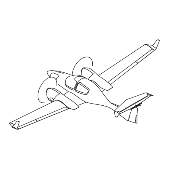
General DA 42 NG AFM 1.7 THREE-VIEW DRAWING Page 1 - 20 Rev. 6 01-Apr-2014 Doc. No. 7.01.15-E... -
Page 39: G1000 Avionics System
DA 42 NG AFM General 1.8 G1000 AVIONICS SYSTEM 1. The G1000 Integrated Avionics System is a fully integrated flight, engine, communication, navigation and surveillance instrumentation system. The system consists of a Primary Flight Display (PFD), Multi-Function Display (MFD), audio panel,... - Page 40 The display may indicate clear areas between intense returns, but this does not necessarily mean it is safe to fly between them. As installed on the DA 42 NG, the Garmin GWX 68 has a demonstrated range of 160 nautical miles. Refer to Garmin G1000 Pilot’s Guide for the DA 42NG, P/N 190-00962-( ) in the latest effective issue...
-
Page 41: Source Documentation
DA 42 NG AFM General 1.9 SOURCE DOCUMENTATION This section lists documents, manuals and other literature that were used as sources for the Airplane Flight Manual, and indicates the respective publisher. However, only the information given in the Airplane Flight Manual is valid. -
Page 42: Propeller
General DA 42 NG AFM 1.9.2 PROPELLER Address: mt-propeller Airport Straubing Wallmühle D-94348 Atting GERMANY Phone: +49-9429-9409-0 E-mail: sales@mt-propeller.com Website: www.mt-propeller.de Documents: E-124, Operation and Installation Manual Hydraulically controlled variable pitch propeller MTV -5, -6, -9, -11, -12, -14, -15, -16, -21, -22, -25 1.9.3 AVIONICS SYSTEM... - Page 43 DA 42 NG AFM Operating Limitations CHAPTER 2 OPERATING LIMITATIONS Page INTRODUCTION ........2-3 AIRSPEED .
- Page 44 Operating Limitations DA 42 NG AFM 2.16.6 GARMIN G1000 AVIONICS SYSTEM ....2-40 2.16.7 AUTOPILOT LIMITATIONS ..... . . 2-44 2.16.8 SMOKING .
-
Page 45: Operating Limitations
DA 42 NG AFM Operating Limitations 2.1 INTRODUCTION Chapter 2 of this Airplane Flight Manual provides operating limitations, instrument markings and placards necessary for the safe operation of the airplane, its powerplants, standard systems and standard equipment. The limitations included in this Chapter are approved. -
Page 46: Airspeed
Operating Limitations DA 42 NG AFM 2.2 AIRSPEED Airspeed KIAS Remarks Operating above 1800 kg 122 KIAS Do not make full or abrupt control surface maneuvering (3968 lb) movement above this speed speed. above 1700 kg 119 KIAS (3748 lb) to... -
Page 47: Airspeed Indicator Markings
DA 42 NG AFM Operating Limitations 2.3 AIRSPEED INDICATOR MARKINGS Marking KIAS Significance White arc 62 - 113 KIAS Operating range with flaps fully extended. If MÄM 42-678 is carried out: 64 - 113 KIAS Green arc 69 - 151 KIAS Normal operating range. -
Page 48: Power-Plant Limitations
Operating Limitations DA 42 NG AFM 2.4 POWER-PLANT LIMITATIONS a) Number of engines b) Engine manufacturer Austro Engine c) Engine designation E4-B d) RPM limitations (shown as propeller RPM) Maximum take-off (rpm) 2300 RPM max. 5 min. Maximum continuous (rpm) - Page 49 DA 42 NG AFM Operating Limitations g) Oil quantity Minimum 5.0 l Maximum 7.0 l Maximum oil consumption 0.1 liters/hr h) Oil temperature Minimum - 30 °C Maximum 140 °C If G1000 system software prior to P/N 010-00670-04 is installed: Normal range 50 °C - 125 °C...
- Page 50 Operating Limitations DA 42 NG AFM NOTE A cautionary (yellow) gearbox temperature range is not imposed by the engine manufacturer. However, there is a delay between power changes and gearbox temperature. Therefore, a cautionary range has been added to the G1000...
- Page 51 DA 42 NG AFM Operating Limitations NOTE The fuel pressure is not indicated on the G1000; a fuel pressure warning will illuminate on the PFD if the pressure is below limit. m)Voltage Minimum 24.1 V Maximum 32.0 V n) Amperage...
- Page 52 Operating Limitations DA 42 NG AFM t) Oil specification SAE Grade 5W-30: SHELL HELIX ULTRA ADDINOL SUPER POWER MV 0537 BP VISCO 5000 5W-30 REPSOL ELITE COMMON RAIL 5W30 GULF FORMULA GMX G-ENERGY F SYNTH QUARTZ 9000 ENERGY GULF FORMULA GX...
- Page 53 DA 42 NG AFM Operating Limitations CAUTION Only engine oils conforming to MB 229.5 specification are approved by Austro Engine GmbH to be used for operation. Use only one type of approved E4 engine oil for an oil change. NOTE It is not recommended to mix different SAE grades.
-
Page 54: Engine Instrument Markings
Operating Limitations DA 42 NG AFM 2.5 ENGINE INSTRUMENT MARKINGS Engine instrument markings and their color code significance are shown in the tables below. Indi- Yellow Green Yellow cation arc/bar arc/bar arc/bar arc/bar arc/bar lower caution normal caution upper prohibited... - Page 55 DA 42 NG AFM Operating Limitations Indi- Yellow Green Yellow cation arc/bar arc/bar arc/bar arc/bar arc/bar lower caution normal caution upper prohibited range operating range prohibited range range range Fuel below -30°C -30° to -20°C -20° to 55°C 55° to 60°C above 60°C...
-
Page 56: Warning, Caution And Advisory Alerts
Operating Limitations DA 42 NG AFM 2.6 WARNING, CAUTION AND ADVISORY ALERTS 2.6.1 WARNING, CAUTION AND ADVISORY ALERTS ON THE G1000 NOTE The alerts described in the following are displayed on the Garmin G1000. Section 7.13 includes a detailed description of the alerts. - Page 57 DA 42 NG AFM Operating Limitations Warning Alerts Meaning / Cause (red) L/R GBOX TEMP Left / Right engine gearbox temperature is in the upper red range (too high / >120 °C). L/R FUEL PRESS Left / Right engine fuel pressure is low.
- Page 58 Operating Limitations DA 42 NG AFM Color and Significance of the Caution Alerts on the G1000 Caution Alerts Meaning / Cause (amber) A fault has occurred in the left/right engine ECU A or L/R ECU A FAIL ECU A is being tested during FADEC-test procedure during the 'Before Take-Off Check'.
- Page 59 DA 42 NG AFM Operating Limitations Color and Significance of the Advisory Alerts on the G1000 Advisory Alerts Meaning / Cause (white) L/R GLOW ON Left / Right engine glow plug active. L/R AUXPUMP Fuel transfer from auxiliary to main tank is in progress (if installed).
-
Page 60: Other Warning Alerts
Operating Limitations DA 42 NG AFM 2.6.2 OTHER WARNING ALERTS Warning Alerts on the Instrument Panel Warning Alert Meaning / Cause (red) GEAR UNSAFE Illuminates if the landing gear is neither in the final up nor in WARNING LIGHT the down & locked position. -
Page 61: Mass (Weight)
DA 42 NG AFM Operating Limitations 2.7 MASS (WEIGHT) Mass (Weight) Value Minimum flight mass 1450 kg 3197 lb Maximum take-off mass 1900 kg 4189 lb Maximum take-off mass (if MÄM 42-678 is carried out) 1999 kg 4407 lb Maximum zero fuel mass... - Page 62 Operating Limitations DA 42 NG AFM NOTE In some countries the beginning of a flight is defined by starting the powerplant. In those countries a ramp mass of maximal MTOM + 8 kg (MTOM + 18 lb) is approved. At the time of lift-off the maximum permitted take-off mass must not be exceeded.
-
Page 63: Center Of Gravity
DA 42 NG AFM Operating Limitations 2.8 CENTER OF GRAVITY Datum Plane The datum plane (DP) is a plane which is normal to the airplane’s longitudinal axis and in front of the airplane as seen from the direction of flight. The airplane’s longitudinal axis is parallel with the floor of the nose baggage compartment. - Page 64 Operating Limitations DA 42 NG AFM WARNING Exceeding the center of gravity limitations reduces the controllability and stability of the airplane. EASA Page 2 - 22 Rev. 6 01-Apr-2014 Doc. No. 7.01.15-E approved...
-
Page 65: Approved Maneuvers
DA 42 NG AFM Operating Limitations 2.9 APPROVED MANEUVERS The airplane is certified in the Normal Category in accordance with JAR-23. Approved Maneuvers 1) All normal flight maneuvers; 2) Stalling (with the exception of dynamic stalling); and 3) Lazy Eights, Chandelles, as well as steep turns and similar maneuvers, in which an angle of bank of not more than 60°... -
Page 66: Maneuvering Load Factors
Operating Limitations DA 42 NG AFM 2.10 MANEUVERING LOAD FACTORS NOTE The tables below show structural limitations. The load factor limits for the engine must also be observed. Refer to the corresponding Operation Manual for the engine. at v at v... -
Page 67: Operating Altitude
DA 42 NG AFM Operating Limitations 2.11 OPERATING ALTITUDE The maximum operating altitude is 18,000 ft (5,486 m) pressure altitude. 2.12 FLIGHT CREW Minimum crew 1 (one person) Maximum number of occupants 4 (four persons) 2.13 KINDS OF OPERATION Provided that national operational requirements are met, the following kinds of operation are approved: •... - Page 68 Operating Limitations DA 42 NG AFM NOTE Many of the items of minimum equipment listed in the following table are integrated in the G1000. for Daytime in Addition for in Addition for VFR Flights Night VFR Flights IFR Flights Flight &...
- Page 69 DA 42 NG AFM Operating Limitations for Daytime in Addition for in Addition for VFR Flights Night VFR Flights IFR Flights Engine * Fuel qty. (2x) * Ammeter instruments * Oil press. (2x) * Voltmeter * Oil temp. (2x) * Coolant temp. (2x)
- Page 70 Operating Limitations DA 42 NG AFM for Daytime in Addition for in Addition for VFR Flights Night VFR Flights IFR Flights Other * Stall warning * Pitot heating * Emergency battery operational system system (for backup attitude minimum gyro and flood light)
-
Page 71: Fuel
DA 42 NG AFM Operating Limitations 2.14 FUEL Approved fuel grades: JET A, JET A-1 (ASTM D 1655) TS-1 (Russia, GOST 10227-86) TS-1 (Ukraine, GSTU 320.00149943.011-99) RT (Russia, GOST 10227-86) RT (Ukraine GSTU 320.00149943.007-97) No. 3 Jet Fuel (China, GB 6537-2006) JP-8 (F34) (USA, MIL-DTL-83133G-2010) and blends of the above listed fuel grades. - Page 72 Operating Limitations DA 42 NG AFM Any mixture of the different types of fuel additives is not permitted. OPERATION WITH ANTI-MICROBIAL LIFE FUEL ADDITIVES The application of the following additives is permitted: - KATHON FP 1.5 max. 100 ppm - BIOBOR JF max.
- Page 73 DA 42 NG AFM Operating Limitations OPERATION WITH ANTI-ICING FUEL ADDITIVES The application of the following additive is permitted: - PRIST Hi-Flash max. 1500 ppm CAUTION The use of PRIST Hi-Flash fuel additive is only permitted with JET A, JET A-1 (ASTM D 1655) and JP-8 (F34).
-
Page 74: Limitation Placards
Operating Limitations DA 42 NG AFM 2.15 LIMITATION PLACARDS All limitation placards are shown below. A list of all placards is included in the Airplane Maintenance Manual (Doc. No. 7.02.15), Chapter 11. The following limitation placards are in the forward view of the pilot: Limitations for GFC 700 Autopilot System: Autopilot / Yaw Damper DISC during take-off and landing. - Page 75 DA 42 NG AFM Operating Limitations LANDING GEAR = 188 KIAS = 152 KIAS If OÄM 42-179 is not incorporated: GPS NOT APPROVED FOR WAAS OPERATIONS On the Emergency Landing Gear Extension Lever: EMERGENCY Gear Extension Max. 152 KIAS On the Instrument Panel:...
- Page 76 Operating Limitations DA 42 NG AFM Next to the Fuel Selector: Crossfeed with fuel pump ON in emergencies only (a) Next to Each of the Two Fuel Filler Necks; (b) In Addition Next to Each of the Two Auxiliary Fuel Filler Necks (if installed):...
- Page 77 DA 42 NG AFM Operating Limitations In Each Cowling, on the Door for the Oil Filler Neck: WARNING APPROVED FUEL JET-A1 or see Airplane Flight Manual Next to the Flap Selector Switch: Flaps KIAS KIAS EASA Doc. No. 7.01.15-E Rev. 6...
- Page 78 Operating Limitations DA 42 NG AFM Next to the Cabin Baggage Compartment: If OÄM 42-207 is carried out: EASA Page 2 - 36 Rev. 6 01-Apr-2014 Doc. No. 7.01.15-E approved...
- Page 79 DA 42 NG AFM Operating Limitations In the Cabin, on the Left Fuselage Sidewall: In the Nose Baggage Compartment: Max. Baggage: 30 kg [66 lb] Beside the Door Locking Device Installed in the Passengers' Door: EMERGENCY EXIT: The keylock must be...
-
Page 80: Other Limitations
Operating Limitations DA 42 NG AFM 2.16 OTHER LIMITATIONS 2.16.1 FUEL TEMPERATURE If G1000 system software prior to P/N 010-00670-06 is installed: From -25 °C to 60 °C (from -13 °F to 140 °F). If G1000 system software P/N 010-00670-06 or later is installed: From -30 °C to 60 °C (from -22 °F to 140 °F). -
Page 81: Electronic Equipment
DA 42 NG AFM Operating Limitations 2.16.5 ELECTRONIC EQUIPMENT The use and switching on of electronic equipment other than that which is part of the equipment of the airplane is not permitted, as it could lead to interference with the airplane's avionics. - Page 82 Operating Limitations DA 42 NG AFM 2.16.6 GARMIN G1000 AVIONICS SYSTEM The Garmin G1000 Cockpit Reference Guide, P/N 190-00963-( ), appropriate revision must be immediately available to the flight crew. The G1000 must utilize the software Garmin 010-00670-01 approved software in accordance with the mandatory service bulletin DAI MSB 42NG-003, latest version.
- Page 83 DA 42 NG AFM Operating Limitations NOTE The database version is displayed on the MFD power-up page immediately after system power-up and must be acknowledged. The remaining system software versions can be verified on the AUX group sub-page 5, "AUX-SYSTEM STATUS".
- Page 84 Operating Limitations DA 42 NG AFM When an alternate airport is required by the applicable operating rules, it must be served by an approach based on other than GPS or Loran-C navigation, the airplane must have the operational equipment capable of using that navigation aid, and the required navigation aid must be operational.
- Page 85 DA 42 NG AFM Operating Limitations 6. When AHRS is required to meet the items listed in the minimum operational equipment (serviceable) table in Section 2.13 of this AFM, operation is prohibited in the following areas: North of 72° N latitude at all longitudes.
- Page 86 AUTOPILOT circuit breaker is prohibited until the cause of the malfunction has been determined and corrected. 4. The Garmin G1000 Cockpit Reference Guide for the Diamond DA 42 NG, P/N 010-00963-( ) approved revision must be immediately available to the flight crew.
- Page 87 DA 42 NG AFM Operating Limitations The GFC 700 components must utilize the following or later approved software versions: Sub-System Software Version v9.03 GDC 74 v3.02 GEA 7X v2.07 v3.03 GIA 6X v5.65 GIA Audio v2.03 GMAX347 v4.01 GMU44 v2.01 GRS 77 v2.11...
- Page 88 Operating Limitations DA 42 NG AFM The GFC 700 AFCS pre-flight test must be successfully completed prior to use of the autopilot, flight director, yaw damper or manual electric trim. A pilot with the seat belt fastened must occupy the left pilot's seat during all operations.
-
Page 89: Emergency Procedures
Emergency DA 42 NG AFM Procedures CHAPTER 3 EMERGENCY PROCEDURES Page INTRODUCTION ........3-4 3.1.1 GENERAL . - Page 90 Emergency DA 42 NG AFM Procedures 3.4.6 HDG ......... . 3-19 G1000 FAILURES .
- Page 91 Emergency DA 42 NG AFM Procedures 3.10 FAILURES IN THE ELECTRICAL SYSTEM ....3-57 3.10.1 COMPLETE FAILURE OF THE ELECTRICAL SYSTEM . . 3-57 3.10.2 HIGH CURRENT .
-
Page 92: Introduction
Emergency DA 42 NG AFM Procedures 3.1 INTRODUCTION 3.1.1 GENERAL This chapter contains checklists as well as the description of recommended procedures to be followed in the event of an emergency. Engine failure or other airplane-related emergencies are most unlikely to occur if the prescribed procedures for pre-flight checks and airplane maintenance are followed. -
Page 93: Certain Airspeeds In Emergencies
Emergency DA 42 NG AFM Procedures 3.1.2 CERTAIN AIRSPEEDS IN EMERGENCIES Event One engine inoperative minimum FLAPS UP 76 KIAS control speed (air) v FLAPS APP 73 KIAS One engine inoperative speed for 85 KIAS best rate of climb v 3.1.3 SELECTING EMERGENCY FREQUENCY... -
Page 94: Airplane-Related G1000 Warnings
Emergency DA 42 NG AFM Procedures 3.2 AIRPLANE-RELATED G1000 WARNINGS 3.2.1 WARNINGS / GENERAL "Warning" means that the non-observation of the corresponding procedure leads to an immediate or important degradation in flight safety. The warning text is displayed in red color. - Page 95 Emergency DA 42 NG AFM Procedures During cruise: Reduce power on affected engine. Increase airspeed. Check coolant temperature in green range. CAUTION If high coolant temperature is indicated and the L/R COOL LVL caution message is not displayed, it can be assumed that there is no technical defect in the cooling system and that the above mentioned procedure can decrease the temperature(s).
-
Page 96: L/R Oil Temp
Emergency DA 42 NG AFM Procedures 3.2.3 L/R OIL TEMP L/R OIL TEMP Left / Right engine oil temperature is in the upper red range (too high / above 140 °C). Oil temperatures above the limit value of 140 °C can lead to a total loss of power due to engine failure. - Page 97 Emergency DA 42 NG AFM Procedures CAUTION If high oil temperature is announced and the oil pressure indication is within the green range, it can be assumed that there is no technical defect in the engine oil system and that the above mentioned procedure can decrease the temperature(s).
-
Page 98: L/R Oil Pres
Emergency DA 42 NG AFM Procedures 3.2.4 L/R OIL PRES If G1000 system software prior to P/N 010-00670-06 is installed: Left / Right engine oil pressure is in the lower red L/R OIL PRES range (too low / <1.5 bar). -
Page 99: L/R Gbox Temp
Emergency DA 42 NG AFM Procedures 3.2.5 L/R GBOX TEMP Left / Right engine gearbox temperature is in the L/R GBOX TEMP upper red range (too high / above 120 °C). Gearbox temperatures above the limit value of 120 °C can lead to a total loss of power due to engine failure. -
Page 100: L/R Fuel Temp
Emergency DA 42 NG AFM Procedures 3.2.6 L/R FUEL TEMP Left / Right fuel temperature is in the upper red range L/R FUEL TEMP (too high / above 60 °C). Fuel temperatures above the limit value of 60 °C can lead to a noticeable reduction of the high pressure pump efficiency. -
Page 101: L/R Fuel Press
Emergency DA 42 NG AFM Procedures 3.2.7 L/R FUEL PRESS L/R FUEL PRESS Left / Right engine fuel pressure is low. 1. Fuel quantity ......check 2. -
Page 102: L/R Altn Amps
Emergency DA 42 NG AFM Procedures 3.2.8 L/R ALTN AMPS Left / Right engine alternator output is in the upper red L/R ALTN AMPS range (too high / above 70 Amps). Proceed according to: 3.10.2 - HIGH CURRENT Page 3 - 14 Rev. -
Page 103: L/R Eng Fire
Emergency DA 42 NG AFM Procedures 3.2.9 L/R ENG FIRE L/R ENG FIRE Left / Right engine fire detected. Engine fire can lead to a total loss of power due to engine failure as well as severe structural damage. Proceed according to the following procedures as applicable: 3.11.1 - ENGINE FIRE ON GROUND... -
Page 104: Door Open
Emergency DA 42 NG AFM Procedures 3.2.11 DOOR OPEN Front and/or rear canopy and/or baggage door are/is DOOR OPEN not closed and locked. Proceed according to: 3.12.2 - UNLOCKED DOORS Page 3 - 16 Rev. 6 01-Apr-2014 Doc. No. 7.01.15-E... -
Page 105: Airplane-Related G1000 Cautions
Emergency DA 42 NG AFM Procedures 3.3 AIRPLANE-RELATED G1000 CAUTIONS 3.3.1 L/R ALTN FAIL Left / Right engine alternator has failed. L/R ALTN FAIL (a) One Alternator Failed Proceed according to: 4B.4.6 - L/R ALTN FAIL (b) Both Alternators Failed... -
Page 106: G1000 System Warnings
Emergency DA 42 NG AFM Procedures 3.4 G1000 SYSTEM WARNINGS 3.4.1 RED X A red X through any display field, such as COM frequencies, NAV frequencies, or engine data, indicates that display field is not receiving valid data. 3.4.2 ATTITUDE FAIL... -
Page 107: Vert Speed Fail
Emergency DA 42 NG AFM Procedures 3.4.5 VERT SPEED FAIL The display system is not receiving vertical speed VERT SPEED FAIL input from the air data computer; accompanied by a red X through the vertical speed display. Determine vertical speed based on the change of altitude information. -
Page 108: G1000 Failures
Emergency DA 42 NG AFM Procedures 3.5 G1000 FAILURES 3.5.1 NAVIGATION INFORMATION FAILURE If Garmin G1000 GPS navigation information is not available or invalid, utilize remaining operational navigation equipment as required. 3.5.2 PFD OR MFD DISPLAY FAILURE 1. DISPLAY BACKUP button on audio panel . . PUSH... -
Page 109: Ahrs Failure
Emergency DA 42 NG AFM Procedures (b) DISPLAY BACKUP button on audio panel ..PUSH (button will be IN) If the system returns to normal mode, leave the DISPLAY BACKUP button IN and continue. lf the system remains in reversionary mode, or abnormal display behavior such as display flashing occurs, then return the DISPLAY BACKUP button to the OUT position. -
Page 110: Air Data Computer (Adc) Failure
Emergency DA 42 NG AFM Procedures 3.5.4 AIR DATA COMPUTER (ADC) FAILURE NOTE Complete loss of the Air Data Computer is indicated by a red X and yellow text over the airspeed, altimeter, vertical speed, TAS and OAT displays. Some FMS functions, such as true airspeed and wind calculations, will also be lost. -
Page 111: Erroneous Or Loss Of Warning/Caution Annunciators
Emergency DA 42 NG AFM Procedures 3.5.6 ERRONEOUS OR LOSS OF WARNING/CAUTION ANNUNCIATORS NOTE Loss of an annunciator may be indicated when engine or fuel displays show an abnormal or emergency situation and the annunciator is not present. An erroneous annunciator may be identified when an annunciator appears which does not agree with other displays or system information. -
Page 112: Abnormal Engine Behaviour
Emergency DA 42 NG AFM Procedures 3.6 ABNORMAL ENGINE BEHAVIOUR 1. Full power ......apply If the abnormal engine behavior sustains, refer to 3.7 - ONE ENGINE INOPERATIVE... -
Page 113: One Engine Inoperative Procedures
Emergency DA 42 NG AFM Procedures 3.7 ONE ENGINE INOPERATIVE PROCEDURES WARNING In certain combinations of airplane weight, configuration, ambient conditions, speed and pilot skill, negative climb performance result. Refer Chapter 5 - PERFORMANCE for one engine inoperative performance data. -
Page 114: Detecting The Inoperative Engine
Emergency DA 42 NG AFM Procedures 3.7.1 DETECTING THE INOPERATIVE ENGINE NOTE One engine inoperative means an asymmetric loss of thrust, resulting in uncommanded yaw and roll in direction of the so- called "dead" engine (with coordinated controls). To handle this situation it is vital to maintain directional control by mainly rudder and additional aileron input. -
Page 115: Engine Troubleshooting
Emergency DA 42 NG AFM Procedures 3.7.2 ENGINE TROUBLESHOOTING WARNING Control over the flight attitude has priority over attempts to solve the current problem ("first fly the airplane"). NOTE With respect to handling and performance, the left-hand engine (pilots view) is considered the "critical" engine. - Page 116 Emergency DA 42 NG AFM Procedures WARNING Do not increase the POWER lever past the propeller speed of 1975 RPM or the setting determined in step 4. An increase of engine power beyond this setting leads into another power loss.
- Page 117 Emergency DA 42 NG AFM Procedures Otherwise: 3. VOTER switch ..... . . switch back to AUTO to retain ECU redundancy If normal engine operation is restored continue flight and land as soon as possible.
-
Page 118: Engine Securing (Feathering) Procedure
Emergency DA 42 NG AFM Procedures 3.7.3 ENGINE SECURING (FEATHERING) PROCEDURE Shut down and feathering of the affected engine: 1. Affected engine ..... . . identify & verify 2. -
Page 119: Unfeathering & Restarting The Engine In Flight
Emergency DA 42 NG AFM Procedures 3.7.4 UNFEATHERING & RESTARTING THE ENGINE IN FLIGHT If the reason for the shutdown has been ascertained and there is no indication of malfunction or engine fire a restart may be attempted. Restarting the Engine with the Starter... - Page 120 Emergency DA 42 NG AFM Procedures NOTE At airspeeds below 100 KIAS it is possible that the propeller may windmill intermittently. Therefore, care should be taken to ensure that the propeller is stationary when engaging the starter. 1. POWER lever of affected engine ..IDLE 2.
- Page 121 Emergency DA 42 NG AFM Procedures Restarting the Engine by Windmilling If the reason for the shutdown has been ascertained and there is no indication of malfunction or engine fire a restart may be attempted. Maximum restart altitude: 18,000 ft pressure altitude for immediate restart.
- Page 122 Emergency DA 42 NG AFM Procedures NOTE Below 125 KIAS it is possible that the propeller may not windmill continuously. Continuous windmilling is required for a successful restart. Above 145 KIAS a restart can overspeed the propeller. 1. POWER lever of affected engine ..IDLE 2.
-
Page 123: Engine Failure During Take-Off
Emergency DA 42 NG AFM Procedures 3.7.5 ENGINE FAILURE DURING TAKE-OFF a) Engine Failure During Ground Roll - Abort take-off. 1. POWER lever ......IDLE / BOTH 2. - Page 124 Emergency DA 42 NG AFM Procedures b) Engine Failure After Lift Off If the landing gear is still extended and the remaining runway / surface is adequate: - Abort the take-off and land straight ahead. If the remaining runway / surface is inadequate: - Decide whether to abort or to continue the take-off.
- Page 125 Emergency DA 42 NG AFM Procedures 6. Inoperative engine ....secure according to 3.7.3 - ENGINE SECURING (FEATHERING) PROCEDURE Land as soon as possible according to 3.7.7 - LANDING WITH ONE ENGINE INOPERATIVE.
-
Page 126: Engine Failures In Flight
Emergency DA 42 NG AFM Procedures 3.7.6 ENGINE FAILURES IN FLIGHT (a) Engine Failure During Initial Climb WARNING As the climb is a flight condition which is associated with high power settings, airspeeds lower than v = 76 KIAS (flaps UP) or 73 KIAS (flaps APP) should be avoided as a sudden engine failure can lead to loss of control. - Page 127 Emergency DA 42 NG AFM Procedures (b) Engine Failure During Flight 1. Rudder ......maintain directional control 2.
-
Page 128: Landing With One Engine Inoperative
Emergency DA 42 NG AFM Procedures 3.7.7 LANDING WITH ONE ENGINE INOPERATIVE Preparation: CAUTION For emergency landing the adjustable backrests (if installed) must be fixed in the upright position. 1. Adjustable backrests (if installed) ..adjust to the upright position... - Page 129 Emergency DA 42 NG AFM Procedures Inoperative engine: 7. Engine ......check secured (feathered) according to 3.7.3 - ENGINE...
- Page 130 Emergency DA 42 NG AFM Procedures 14. POWER lever ......as required 15. Trim ....... . as required / directional trim to...
-
Page 131: Go-Around / Balked Landing With One Engine Inoperative
Emergency DA 42 NG AFM Procedures If the approach to land is not successful you may consider: 3.7.8 GO-AROUND / BALKED LANDING WITH ONE ENGINE INOPERATIVE CAUTION The go-around / balked landing is not recommended to be initiated below a minimum of 800 ft above ground. - Page 132 Emergency DA 42 NG AFM Procedures If a positive rate of climb cannot be established: - Land so as to keep clear of obstacles. If time allows the following steps can reduce the risk of fire in an event of collision with obstacles after touchdown: 6.
- Page 133 Emergency DA 42 NG AFM Procedures If landing with landing gear extended: 10. LANDING GEAR ..... . DOWN, check 3 green 11.
-
Page 134: Flight With One Engine Inoperative
Emergency DA 42 NG AFM Procedures 3.7.9 FLIGHT WITH ONE ENGINE INOPERATIVE CAUTION Even if a positive flight performance can be established with one engine inoperative, land as soon as possible at the next suitable airfield / airport. 1. Airspeed ......above v... - Page 135 Emergency DA 42 NG AFM Procedures NOTE If the FUEL SELECTOR is set on CROSSFEED, the engine will be supplied with fuel from the main tank on the opposite side. This will extend range and helps to keep the wings laterally balanced (see 2.14 - FUEL).
-
Page 136: Engines Out Landing
Emergency DA 42 NG AFM Procedures 3.8 ENGINES OUT LANDING 1. ENGINE MASTER ....both OFF 2. Alternator switches ....both OFF 3. - Page 137 Emergency DA 42 NG AFM Procedures If landing with landing gear extended: 9. LANDING GEAR ..... . DOWN, check 3 green 10.
-
Page 138: Landing Gear System Failures
Emergency DA 42 NG AFM Procedures 3.9 LANDING GEAR SYSTEM FAILURES 3.9.1 LANDING GEAR UNSAFE WARNING NOTE The landing gear unsafe warning light illuminates if the landing gear is neither in the final up or down & locked position. Illumination of this light is therefore normal during transit. - Page 139 Emergency DA 42 NG AFM Procedures NOTE If the landing gear cannot be retracted to the final up position you may continue the flight with the landing gear extended in the down & locked position. Consider for higher aerodynamic drag, resulting in degraded flight performance, increased fuel consumption and decreased range.
-
Page 140: Manual Extension Of The Landing Gear
Emergency DA 42 NG AFM Procedures 3.9.2 MANUAL EXTENSION OF THE LANDING GEAR NOTE In case of a failure of the electrical pump, which is driving the landing gear actuators, the landing gear can be extended manually at speeds up to 152 KIAS. The manual extension of the landing gear may take up to 20 seconds. - Page 141 Emergency DA 42 NG AFM Procedures 7. Gear indicator lights ....check 3 green lights NOTE If the landing gear is correctly extended and locked, as indicated by the 3 green lights, the red light is illuminated additionally if the GEAR circuit breaker is pulled.
-
Page 142: Landing With Gear Up
Emergency DA 42 NG AFM Procedures 3.9.3 LANDING WITH GEAR UP NOTE This procedure applies if the landing gear is completely retracted. 1. Approach ......with power at normal approach airspeeds and flap settings 2. -
Page 143: Gear
Emergency DA 42 NG AFM Procedures 3.9.4 LANDING WITH A DEFECTIVE TIRE ON THE MAIN LANDING GEAR CAUTION A defective (e.g. burst) tire is not usually easy to detect. The damage normally occurs during take-off or landing, and is hardly noticeable during fast taxiing. It is only during the roll- out after landing or at lower taxiing speeds that a tendency to swerve occurs. -
Page 144: Landing With Defective Brakes
Emergency DA 42 NG AFM Procedures 3.9.5 LANDING WITH DEFECTIVE BRAKES Consider the greater rolling distance. Safety harness ......check fastened and tightened... -
Page 145: Failures In The Electrical System
Emergency DA 42 NG AFM Procedures 3.10 FAILURES IN THE ELECTRICAL SYSTEM 3.10.1 COMPLETE FAILURE OF THE ELECTRICAL SYSTEM 1. Circuit breakers ..... . check if all OK (pressed in) If there is still no electrical power available: 2. -
Page 146: High Current
Emergency DA 42 NG AFM Procedures Make use of the stand-by airspeed indicator and altimeter. Engine power can be set via visual reference of the POWER lever position. END OF CHECKLIST 3.10.2 HIGH CURRENT If high current is indicated on the G1000: 1. -
Page 147: Smoke And Fire
Emergency DA 42 NG AFM Procedures 3.11 SMOKE AND FIRE NOTE The cabin hand fire extinguisher is located inside the airplane passenger compartment on the RH side of the cabin floor behind the co-pilot seat. To release the fire extinguisher bottle out of the bracket, it is necessary to catch the bottle at the agent-outlet nozzle near the Y-spring. -
Page 148: Engine Fire During Take-Off
Emergency DA 42 NG AFM Procedures 3.11.2 ENGINE FIRE DURING TAKE-OFF 1. Cabin heat & Defrost ....OFF CAUTION In case of extreme smoke development, the front canopy may be unlatched during flight. -
Page 149: Engine Fire In Flight
Emergency DA 42 NG AFM Procedures 3.11.3 ENGINE FIRE IN FLIGHT 1. Cabin heat & Defrost ....OFF CAUTION In case of extreme smoke development, the front canopy may be unlatched during flight. - Page 150 Emergency DA 42 NG AFM Procedures 3.11.4 ELECTRICAL FIRE ON GROUND 1. ELECT. MASTER ..... OFF If the engine is running: 2.
-
Page 151: Electrical Fire In Flight
Emergency DA 42 NG AFM Procedures 3.11.5 ELECTRICAL FIRE IN FLIGHT 1. EMERGENCY SWITCH ....ON 2. AVIONIC MASTER ....OFF 3. -
Page 152: Other Emergencies
Emergency DA 42 NG AFM Procedures 3.12 OTHER EMERGENCIES 3.12.1 SUSPICION OF CARBON MONOXIDE CONTAMINATION IN THE CABIN Carbon monoxide (CO) is a gas which is developed during the combustion process. It is poisonous and without smell. Increased concentration of carbon monoxide gas can be fatal. -
Page 153: Unlocked Doors
Emergency DA 42 NG AFM Procedures 3.12.2 UNLOCKED DOORS 1. Airspeed ......reduce immediately 2. - Page 154 Emergency DA 42 NG AFM Procedures Front Baggage Door Open 5. Airspeed ......reduce, so that door is in a stable position 6.
-
Page 155: Defective Propeller Rpm Regulating System
Emergency DA 42 NG AFM Procedures 3.12.3 DEFECTIVE PROPELLER RPM REGULATING SYSTEM CAUTION The POWER lever should be moved slowly, in order to avoid over-speeding and excessively rapid RPM changes. The light wooden propeller blades produce more rapid RPM changes than metal blades. - Page 156 Emergency DA 42 NG AFM Procedures (b) Propeller Overspeed NOTE This procedure applies for continued propeller overspeed due to a malfunction in the propeller constant speed unit or a engine control unit malfunction. 1. POWER setting ..... . . reduce as required If the problem does not clear: 2.
- Page 157 Emergency DA 42 NG AFM Procedures (c) Fixed RPM 1. POWER setting ..... . change If the problem does not clear: 2.
-
Page 158: Unintentional Flight Into Icing
Emergency DA 42 NG AFM Procedures 3.12.4 UNINTENTIONAL FLIGHT INTO ICING 1. Leave the icing area (by changing altitude or turning back, in order to reach zones with a higher ambient temperature). 2. PITOT HEAT ......ON 3. - Page 159 Emergency DA 42 NG AFM Procedures 3.12.5 FUEL SUPPLY FAILURE 1. FUEL SELECTOR ....CROSSFEED / affected engine WARNING In case of a fuel supply failure a fuel pump inspection is required prior to the next flight.
-
Page 160: Recovery From An Unintentional Spin
Emergency DA 42 NG AFM Procedures 3.12.6 RECOVERY FROM AN UNINTENTIONAL SPIN CAUTION Spin recovery has NOT been shown during certification as it is NOT required for this airplane category. The given recovery method is based on general experience! CAUTION Intentional spins are prohibited in this airplane. - Page 161 Emergency DA 42 NG AFM Procedures When rotation has stopped: 6. Rudder ......neutral 7.
- Page 162 Emergency DA 42 NG AFM Procedures 3.12.7 EMERGENCY DESCENT 1. FLAPS ......UP 2.
- Page 163 Emergency DA 42 NG AFM Procedures 3.12.9 AUTOPILOT OR ELECTRIC TRIM MALFUNCTION / FAILURE NOTE An autopilot or electric trim malfunction may be recognized by an unexpected deviation from the desired flight path, abnormal flight control or trim wheel movement, or flight director commands which cause unexpected or contradictory information on the other cockpit displays.
- Page 164 Emergency DA 42 NG AFM Procedures NOTE Accomplish items 1 and 2 simultaneously! 1. Airplane control stick ....grasp firmly and regain airplane control 2.
- Page 165 Normal Operating DA 42 NG AFM Procedures CHAPTER 4A NORMAL OPERATING PROCEDURES Page 4A.1 INTRODUCTION ........4A-3 4A.2 AIRSPEEDS FOR NORMAL OPERATING PROCEDURES .
- Page 166 Normal Operating DA 42 NG AFM Procedures 4A.6.13 AFTER LANDING ......4A-59 4A.6.14 SHUT-DOWN .
- Page 167 Normal operating procedures for GFC 700 are described in Garmin G1000 Cockpit Reference Guide, P/N 190-00963-00 or later and the Garmin G1000 Pilot’s Guide for the Diamond DA 42 NG, P/N 190-00962-00 or later. Doc. No. 7.01.15-E Rev. 6 01-Apr-2014 Page 4A - 3...
-
Page 168: Airspeeds For Normal Operating Procedures
Normal Operating DA 42 NG AFM Procedures 4A.2 AIRSPEEDS FOR NORMAL OPERATING PROCEDURES FLAPS up to 1900 kg above 1900 kg (4189 lb) (4189 lb) Airspeed for rotation (take-off run, min. 80 KIAS min. 80 KIAS min. 76 KIAS min. 76 KIAS Airspeed for take-off climb min. -
Page 169: Advisory Alerts On The G1000
Normal Operating DA 42 NG AFM Procedures 4A.3 ADVISORY ALERTS ON THE G1000 The G1000 provides the following advisory-alerts on the PFD in the alert area: 4A.3.1 ADVISORY/GENERAL White color coded text. CHARACTERISTICS 4A.3.2 L/R GLOW ON L/R GLOW ON Left / Right engine glow plug active. -
Page 170: Flight Characteristics
Procedures 4A.4 FLIGHT CHARACTERISTICS The DA 42 NG is to be flown with "the feet on the pedals“, meaning that coordinated flight in all phases and configurations shall be supported by dedicated use of the rudder and ailerons together. With the landing gear extended and at aft CG-locations, with flaps up and full power... -
Page 171: Checklists For Normal Operating Procedures
Normal Operating DA 42 NG AFM Procedures 4A.6 CHECKLISTS FOR NORMAL OPERATING PROCEDURES 4A.6.1 PRE-FLIGHT INSPECTION I. Cabin Check Preparation: Parking brake ......set ON MET, NAV, mass and balance . - Page 172 Normal Operating DA 42 NG AFM Procedures On the Instrument Panel: ALTERNATOR ..... . . check ON VOTER switch ......check AUTO PITOT HEAT .
- Page 173 Normal Operating DA 42 NG AFM Procedures b) Fuel quantity ......check indication, verify using alternate means (see Section 7.9.5)
- Page 174 Normal Operating DA 42 NG AFM Procedures h) POWER lever ......set MAX Variable elevator backstop ....check function/control stick must...
- Page 175 Normal Operating DA 42 NG AFM Procedures II. Walk-Around Check, Visual Inspection CAUTION A visual inspection means: examination for damage, cracks, delamination, excessive play, load transmission, correct attachment and general condition. In addition control surfaces should be checked for freedom of movement.
- Page 176 Normal Operating DA 42 NG AFM Procedures 2. Left Engine Nacelle: a) 3 air inlets / 2 air outlets ....clear b) Engine oil level ..... . . check dipstick (inspection hole in the upper cowling) c) Gearbox oil level .
- Page 177 Normal Operating DA 42 NG AFM Procedures Nacelle underside ..... check for excessive contamination particularly by oil, fuel, and other fluids k) Auxiliary tank vent outlet on lower surface (if installed) .
- Page 178 Normal Operating DA 42 NG AFM Procedures Tie-down ......check, clear m) Aileron and linkage ....visual inspection n) Aileron hinges and safety pin .
- Page 179 Normal Operating DA 42 NG AFM Procedures 6. Fuselage, Right Side: a) Fuselage skin ......visual inspection b) Rear window .
- Page 180 Normal Operating DA 42 NG AFM Procedures e) Openings on lower surface ....check for foreign objects and for traces of fuel (if tank is full, fuel...
- Page 181 Normal Operating DA 42 NG AFM Procedures f) Venting pipe ......check for blockage g) Exhaust ......visual inspection WARNING The exhaust can cause burns when hot.
- Page 182 Normal Operating DA 42 NG AFM Procedures 10. Front Fuselage and Nose Landing Gear: a) Left and right front baggage door ..visual inspection, closed and locked b) Nose landing gear strut ....visual inspection, sufficient height (typical visible length of bare piston: at least 15 cm/5.9 in)
-
Page 183: 6.2 Before Starting Engine
Normal Operating DA 42 NG AFM Procedures 4A.6.2 BEFORE STARTING ENGINE 1. Preflight inspection ....complete 2. Passengers ......instructed... - Page 184 Normal Operating DA 42 NG AFM Procedures NOTE The pilot must ensure that a passenger sitting on a front seat is instructed in the operation of the adjustable backrest (if installed). 5. Adjustable backrests (if installed) ..adjust to the upright...
- Page 185 Normal Operating DA 42 NG AFM Procedures 16. G1000 ......wait until power-up completed.
-
Page 186: 6.3 Starting Engine
Normal Operating DA 42 NG AFM Procedures 4A.6.3 STARTING ENGINE NOTE At ambient temperatures below -22°C the engine may not start at the first attempt. In this case wait 60 seconds between the start attempts. 1. Strobe lights (ACL) ....ON 2. - Page 187 Normal Operating DA 42 NG AFM Procedures CAUTION Do not overheat the starter motor. Do not operate the starter motor for more than 10 seconds. At ambient temperatures below -22°C it is possible that the engine will not start at the first attempt. In this case wait 60 seconds between the start attempts.
- Page 188 Normal Operating DA 42 NG AFM Procedures 4A.6.4 BEFORE TAXIING 1. Power lever ......as required, max. 50% if engine temperature below green range.
- Page 189 Normal Operating DA 42 NG AFM Procedures NOTE The AFCS system automatically conducts a preflight self-test upon initial power application. The preflight test is indicated by a white boxed PFT on the PFD. Upon successful completion of the preflight test, the PFT is removed, the red AFCS annunciation is removed, and the autopilot disconnect tone sounds.
-
Page 190: 6.5 Taxiing
Normal Operating DA 42 NG AFM Procedures 4A.6.5 TAXIING 1. Parking brake ......release 2. Brakes ......test on moving off 3. -
Page 191: 6.6 Before Take-Off
Normal Operating DA 42 NG AFM Procedures 4A.6.6 BEFORE TAKE-OFF 1. Position airplane into wind if possible. 2. Parking brake ......set... - Page 192 Normal Operating DA 42 NG AFM Procedures 9. Annunciations / Engine / System Page ..check OK / normal range (except oil pressure may be in the yellow range with a warm engine and power lever set to IDLE) 10.
- Page 193 Normal Operating DA 42 NG AFM Procedures ECU / fuel pumps test sequence: CAUTION If the L/R ECU A/B FAIL indicators do not illuminate during the test sequence there is a malfunction in the engine control system. Terminate flight preparation.
- Page 194 Normal Operating DA 42 NG AFM Procedures 1. Power lever ......IDLE 2. Propeller RPM ......check below 1000 RPM 3.
- Page 195 Normal Operating DA 42 NG AFM Procedures 8. ECU TEST button ..... release NOTE By switching between ECU A and B the two independent electrical fuel pumps are switched over as well.
- Page 196 Normal Operating DA 42 NG AFM Procedures Available Power Check: 1. POWER lever ......MAX for 10 seconds 2.
-
Page 197: 6.7 Take-Off
Normal Operating DA 42 NG AFM Procedures 4A.6.7 TAKE-OFF Standard Procedure (Take-Off with Flaps UP) 1. Transponder ......as required 2. - Page 198 Normal Operating DA 42 NG AFM Procedures When safe climb is established: 7. LANDING GEAR ..... . apply brakes; UP,...
- Page 199 Normal Operating DA 42 NG AFM Procedures NOTE In strong crosswinds steering can be augmented by use of the toe brakes. It should be noted, however, that this method increases the take-off roll, and should not generally be used. 6. Nose wheel lift-off ..... 76 KIAS 7.
-
Page 200: 6.8 Climb
Normal Operating DA 42 NG AFM Procedures 4A.6.8 CLIMB Initial Climb Check 1. Landing light ......OFF / as required 2. - Page 201 Normal Operating DA 42 NG AFM Procedures GFC 700 Operation During Climb NOTE The NOSE UP and NOSE DN buttons on the mode controller on the MFD are referenced to airplane movement. The NOSE UP button will increase the reference pitch attitude, increase the reference vertical speed and decrease the reference airspeed.
- Page 202 Normal Operating DA 42 NG AFM Procedures b) Flight Level Change (FLC) 1. Altitude preselect ..... . set to desired altitude 2.
- Page 203 Normal Operating DA 42 NG AFM Procedures c) To Capture a Selected Altitude 1. Altimeter setting ..... . adjust to appropriate value 2.
- Page 204 Normal Operating DA 42 NG AFM Procedures d) Navigation Capture and Track: 1. Navigation source ..... select VOR or GPS using CDI button on PFD 2.
- Page 205 Normal Operating DA 42 NG AFM Procedures 4A.6.9 CRUISE 1. POWER lever ......up to 92% or maximum...
- Page 206 Normal Operating DA 42 NG AFM Procedures 2. Transfer the second half of the auxiliary fuel: Repeat the procedure described above. NOTE Transfer the fuel from the auxiliary tanks to the main tanks as soon as possible. The fuel in the auxiliary tanks must be transferred to the main tanks to become available for the current flight mission.
- Page 207 Normal Operating DA 42 NG AFM Procedures NOTE If the altitude preselect is not changed before selecting VS, the autopilot may re-capture the current altitude immediately after entering VS mode. Always ensure that the altitude preselect is adjusted prior to selecting VS.
- Page 208 Normal Operating DA 42 NG AFM Procedures NOTE If the altitude preselect is not changed before selecting FLC, the autopilot may re-capture the current altitude immediately after entering FLC mode. Always ensure that the altitude preselect is adjusted prior to selecting FLC.
- Page 209 Normal Operating DA 42 NG AFM Procedures NOTE In ALT mode, the autopilot will maintain the reference altitude shown in the autopilot window of the PFD regardless of the altitude in the altitude preselect window or the altimeter's barometric pressure setting. If the altimeter setting is changed, the autopilot will climb or descend to maintain the reference altitude.
- Page 210 Normal Operating DA 42 NG AFM Procedures e) Navigation Capture and Track: 1. Navigation source ..... select VOR or GPS using CDI button on PFD 2.
- Page 211 Normal Operating DA 42 NG AFM Procedures 4A.6.10 DESCENT 1. POWER lever ......as required 2. Airspeed ......as required 3.
- Page 212 Normal Operating DA 42 NG AFM Procedures NOTE If the altitude preselect is not changed before selecting VS, the autopilot may re-capture the current altitude immediately after entering VS mode. Always ensure that the altitude preselect is adjusted prior to selecting VS.
- Page 213 Normal Operating DA 42 NG AFM Procedures NOTE If the altitude preselect is not changed before selecting FLC, the autopilot may re-capture the current altitude immediately after entering FLC mode. Always ensure that the altitude preselect is adjusted prior to selecting FLC.
- Page 214 Normal Operating DA 42 NG AFM Procedures NOTE In ALT mode, the autopilot will maintain the reference altitude shown in the autopilot window of the PFD regardless of the altitude in the altitude preselect window or the altimeter's barometric pressure setting. If the altimeter setting is changed, the autopilot will climb or descend to maintain the reference altitude.
- Page 215 Normal Operating DA 42 NG AFM Procedures 4A.6.11 APPROACH & LANDING Approach: CAUTION For landing the adjustable backrests (if installed) must be fixed in the upright position. 1. Adjustable backrests (if installed) ..adjust to the upright...
- Page 216 Normal Operating DA 42 NG AFM Procedures Before Landing: 12. Airspeed Up to 1900 kg (4189 lb) ....min. 86 KIAS with FLAPS UP min.
- Page 217 Normal Operating DA 42 NG AFM Procedures GFC 700 Operation During Approach and Landing a) VOR 1. Navigation source ..... select VOR using CDI button on PFD 2.
- Page 218 Normal Operating DA 42 NG AFM Procedures b) ILS 1. Navigation source ..... select LOC using CDI button on PFD 2.
- Page 219 Normal Operating DA 42 NG AFM Procedures c) GPS 1. Navigation source ..... select GPS using CDI button on PFD 2.
- Page 220 Normal Operating DA 42 NG AFM Procedures NOTE The course pointer must be at least 115° from the current magnetic heading before BC will be annunciated in the lateral mode field. Until that point, LOC will be annunciated. Selecting NAV mode for back course approaches inhibits the glideslope from coupling.
- Page 221 Normal Operating DA 42 NG AFM Procedures 4A.6.12 GO AROUND 1. POWER lever ......MAX 2. FLAPS ......position APP 3.
- Page 222 Normal Operating DA 42 NG AFM Procedures 3. Balked landing ......execute 4. Missed approach procedure ... . . execute (as applicable) 5.
- Page 223 Normal Operating DA 42 NG AFM Procedures 4A.6.13 AFTER LANDING 1. POWER lever ..... . . IDLE 2. Brakes ......as required 3.
- Page 224 Normal Operating DA 42 NG AFM Procedures 4A.6.14 SHUT-DOWN 1. Parking brake ......set 2. POWER lever ......1 minute at max. 10 % load 3.
- Page 225 Normal Operating DA 42 NG AFM Procedures 4A.6.15 EXIT AIRPLANE Exit the airplane to the aft on designated areas on the inner wing section LH or RH. 4A.6.16 POST FLIGHT INSPECTION 1. Record any problem found in flight and during the post-flight check in the log book.
- Page 226 Normal Operating DA 42 NG AFM Procedures 4A.6.18 OPERATION IN RAIN, SNOW OR VISIBLE MOISTURE 1. ALTERNATE AIR ..... OPEN...
- Page 227 Normal Operating DA 42 NG AFM Procedures 4A.6.19 REFUELING CAUTION Before refueling, the airplane must be connected to electrical ground. Grounding points: exhaust, left and right. Refer to Section 2.14 - FUEL for approved fuel grades. Use of Fuel Additives...
- Page 228 Normal Operating DA 42 NG AFM Procedures Typical Dosing Quantities: (a) KATHON FP 1.5 Fuel Quantity Fuel Additive * Liter US gal 13.2 40.2 88.68 0.13 26.4 80.4 177.37 0.26 39.6 120.6 266.05 11.6 0.39 52.8 160.8 354.73 15.5 0.52 79.3...
- Page 229 Normal Operating DA 42 NG AFM Procedures (c) PRIST Hi-Flash Fuel Quantity Fuel Additive *,** PRIST Hi-Flash (1500 ppm) Liter US gal 13.2 40.2 88.68 58.9 1.99 26.4 80.4 177.37 117.9 3.99 39.6 120.6 266.05 176.8 5.98 52.8 160.8 354.73 235.8...
- Page 230 Normal Operating DA 42 NG AFM Procedures 4A.6.20 FLIGHT AT HIGH ALTITUDE At high altitudes the provision of oxygen for the occupants is necessary. Legal requirements for the provision of oxygen should be adhered to. Refer to Section 2.11 - OPERATING ALTITUDE for more information.
- Page 231 Normal Operating DA 42 NG AFM Procedures NOTE At airspeeds below 100 KIAS it is possible that the propeller may windmill intermittently. Therefore, care should be taken to ensure that the propeller is stationary when engaging the starter. 1. Altitude ......stabilize in level flight at an...
- Page 232 Normal Operating DA 42 NG AFM Procedures Restarting the Engine by Windmilling Minimum restart airspeed ....125 KIAS Maximum restart airspeed ....145 KIAS CAUTION 1.
- Page 233 Normal Operating DA 42 NG AFM Procedures CAUTION After the engine has started, the POWER lever should be set to a moderate power setting until engine temperature has reached the green range. END OF CHECKLIST Doc. No. 7.01.15-E Rev. 6...
- Page 234 Normal Operating DA 42 NG AFM Procedures Intentionally left blank. Page 4A - 70 Rev. 6 01-Apr-2014 Doc. No. 7.01.15-E...
- Page 235 Abnormal Operating DA 42 NG AFM Procedures CHAPTER 4B ABNORMAL OPERATING PROCEDURES Page 4B.1 PRECAUTIONARY LANDING ......4B-3 4B.2 CANOPY IN COOLING GAP POSITION .
- Page 236 Abnormal Operating DA 42 NG AFM Procedures 4B.4.11 STICK LIMIT ....... . . 4B-21 4B.4.12 CHECK GEAR .
- Page 237 Abnormal Operating DA 42 NG AFM Procedures 4B.1 PRECAUTIONARY LANDING NOTE A landing of this type is only necessary when there is a reasonable suspicion that due to operational factors such as fuel shortage, weather conditions, etc. the possibility of endangering the airplane and its occupants by continuing the flight cannot be excluded.
- Page 238 Abnormal Operating DA 42 NG AFM Procedures CAUTION If sufficient time is remaining, the risk of fire in the event of a collision with obstacles can be reduced as follows after a safe touch-down: ENGINE MASTER ..both OFF FUEL SELECTOR .
-
Page 239: Canopy In Cooling Gap Position
Abnormal Operating DA 42 NG AFM Procedures 4B.2 CANOPY IN COOLING GAP POSITION CAUTION If take-off was inadvertently done with the canopy in the cooling gap position, do not attempt to close the canopy in flight. Land the airplane and close the canopy on ground. -
Page 240: 3.2 Coolant Temperature
Abnormal Operating DA 42 NG AFM Procedures 4B.3.2 COOLANT TEMPERATURE (a) High Coolant Temperature Proceed according to: 3.2.2 - L/R ENG TEMP (b) Low Coolant Temperature Check G1000 for L/R COOL LVL caution message (low coolant level) NOTE During an extended descent from high altitudes with a low power setting coolant temperature may decrease. -
Page 241: 3.3 Oil Temperature
Abnormal Operating DA 42 NG AFM Procedures 4B.3.3 OIL TEMPERATURE (a) High Oil Temperature Proceed according to: 3.2.3 - L/R OIL TEMP (b) Low Oil Temperature NOTE During an extended descent from high altitudes with a low power setting oil temperature may decrease. In this case an increase in power can help. -
Page 242: 3.4 Oil Pressure
Abnormal Operating DA 42 NG AFM Procedures 4B.3.4 OIL PRESSURE (a) High Oil Pressure Check oil temperature. Check coolant temperature. If the Temperatures are within the Green Range: Expect false oil pressure indication. Keep monitoring temperatures. If the Temperatures are outside of the Green Range: Reduce power on affected engine. -
Page 243: 3.5 Gearbox Temperature
Abnormal Operating DA 42 NG AFM Procedures 4B.3.5 GEARBOX TEMPERATURE High Gearbox Temperature Proceed according to: 3.2.5 - L/R GBOX TEMP 4B.3.6 FUEL TEMPERATURE (a) High Fuel Temperature Proceed according to: 3.2.6 - L/R FUEL TEMP (b) Low Fuel Temperature Increase power on affected engine. - Page 244 Abnormal Operating DA 42 NG AFM Procedures 4B.3.7 VOLTAGE (a) Low Voltage Indication on the Ground with Engines Running 1. ALTERNATORS ..... . check ON 2.
-
Page 245: Caution-Alerts On The G1000
Abnormal Operating DA 42 NG AFM Procedures 4B.4 CAUTION-ALERTS ON THE G1000 The G1000 provides the following CAUTION-alerts on the PFD in the ALERT area. 4B.4.1 CAUTIONS / GENERAL * Amber color coded text. CHARACTERISTICS * Single warning chime tone of 1.5 seconds duration. -
Page 246: 4.2 L/R Ecu A Fail
Abnormal Operating DA 42 NG AFM Procedures 4B.4.2 L/R ECU A FAIL * Left / Right engine ECU A has failed L/R ECU A FAIL * is being tested during ECU test procedure before take-off check. (a) ECU A Caution on the Ground Terminate flight preparation. -
Page 247: 4.3 L/R Ecu B Fail
Abnormal Operating DA 42 NG AFM Procedures 4B.4.3 L/R ECU B FAIL * Left / Right engine ECU B has failed L/R ECU B FAIL * is being tested during ECU test procedure before take-off check. (a) ECU B Caution on the Ground Terminate flight preparation. -
Page 248: 4.4 L/R Fuel Low
Abnormal Operating DA 42 NG AFM Procedures 4B.4.4 L/R FUEL LOW Left / Right engine main tank fuel quantity is low. L/R FUEL LOW 1. Fuel quantity ......check... -
Page 249: 4.5 Low Voltage Caution (Low Volts)
Abnormal Operating DA 42 NG AFM Procedures 4B.4.5 LOW VOLTAGE CAUTION (LOW VOLTS) Left / Right engine bus voltage is too low (less than L/R VOLTS LOW 25 Volts). Possible reasons are: - A fault in the power supply. - ALTERNATORS off. -
Page 250: 4.6 L/R Altn Fail
Abnormal Operating DA 42 NG AFM Procedures 4B.4.6 L/R ALTN FAIL Left / Right engine alternator has failed. L/R ALTN FAIL NOTE A L/R ALTN FAIL annunciation may be temporarily triggered during ground operation with low engine power settings. This indicates no system malfunction. -
Page 251: 4.7 L/R Cool Lvl
Abnormal Operating DA 42 NG AFM Procedures 4B.4.7 L/R COOL LVL Left / Right engine coolant level is low. L/R COOL LVL A low coolant caution alert may indicate a loss of coolant. This will subsequently lead to decreased engine cooling capability / loss of engine power due to engine failure. -
Page 252: 4.8 Pitot Fail / Ht Off
Abnormal Operating DA 42 NG AFM Procedures 4B.4.8 PITOT FAIL / HT OFF Pitot heating system has failed. PITOT FAIL Pitot heating system is OFF. PITOT HT OFF 1. PITOT HEAT ......check ON / as required... -
Page 253: 4.9 Stall Ht Fail / Off
Abnormal Operating DA 42 NG AFM Procedures 4B.4.9 STALL HT FAIL / OFF Stall warning heat has failed. STAL HT FAIL Stall warning heat is OFF. STAL HT OFF 1. PITOT HEAT ......check ON / as required... -
Page 254: 4.10 L/R Auxiliary Fuel Tank Empty (If Installed)
Abnormal Operating DA 42 NG AFM Procedures 4B.4.10 L/R AUXILIARY FUEL TANK EMPTY (if installed) Left / Right auxiliary fuel tank empty (displayed only L/R AUX FUEL E when AUX PUMP switch is ON). The auxiliary tank empty caution message indicates an empty auxiliary fuel tank while the aux. -
Page 255: 4.11 Stick Limit
Abnormal Operating DA 42 NG AFM Procedures 4B.4.11 STICK LIMIT Control stick limiting system (variable elevator stop) has STICK LIMIT failed. The variable elevator backstop is activated depending on the position of the power levers. The system has two failure modes which can be identified as follows:... -
Page 256: 4.12 Check Gear
Abnormal Operating DA 42 NG AFM Procedures 4B.4.12 CHECK GEAR Landing gear is not down and locked. CHECK GEAR 1. Landing gear ......down / as required... -
Page 257: 4.13 Loi
Abnormal Operating DA 42 NG AFM Procedures 4B.4.13 LOI GPS integrity is insufficient for the current phase of flight. (a) Enroute, Oceanic, Terminal, or Initial Approach Phase of Flight If the LOI annunciation is displayed in the enroute, oceanic, terminal, or initial approach... -
Page 258: Failures In Flap Operating System
Abnormal Operating DA 42 NG AFM Procedures 4.5 FAILURES IN FLAP OPERATING SYSTEM Failure in Position Indication or Function 1. FLAPS position ..... . . check visually 2. -
Page 259: Failures In Electrical Rudder Pedal Adjustment . 4B-25
Abnormal Operating DA 42 NG AFM Procedures 4B.6 FAILURES IN ELECTRICAL RUDDER PEDAL ADJUSTMENT Runaway of Electrical Rudder Pedal Adjustment (Optional Equipment, OÄM 42-070) NOTE The circuit breaker for the rudder pedal adjustment is located below the related switch, on the rear wall of the leg room. -
Page 260: Failures In Hydraulic System
Abnormal Operating DA 42 NG AFM Procedures 4B.7 FAILURES IN HYDRAULIC SYSTEM 4B.7.1 CONTINUOUS HYDRAULIC PUMP OPERATION 1. Landing gear indication lights ... . check 2. Prepare for manual landing gear extension. Refer to Section 3.9.2 - MANUAL EXTENSION OF THE LANDING GEAR. -
Page 261: 7.2 Hydraulic Pump Failure
Abnormal Operating DA 42 NG AFM Procedures 4B.7.2 HYDRAULIC PUMP FAILURE 1. Landing gear indication lights ... . check 2. Prepare for manual landing gear extension. Refer to Section 3.9.2 - MANUAL EXTENSION OF THE LANDING GEAR. -
Page 262: Starting Engine With External Power
Abnormal Operating DA 42 NG AFM Procedures 4B.8 STARTING ENGINE WITH EXTERNAL POWER 4B.8.1 BEFORE STARTING ENGINE 1. Pre-flight inspection ....complete 2. - Page 263 Abnormal Operating DA 42 NG AFM Procedures 5. Adjustable backrests (if installed) ..adjust to the upright position described by a placard on the roll-over bar and verify proper fixation 6. Rudder pedals ..... . . adjusted; if manual pedal...
- Page 264 Abnormal Operating DA 42 NG AFM Procedures NOTE When switching the External Power Unit ON, all electrical equipment connected to the LH and RH main buses is powered. 19. G1000 ......wait until power-up completed.
-
Page 265: 8.2 Starting Engine
Abnormal Operating DA 42 NG AFM Procedures 4B.8.2 STARTING ENGINE 1. Strobe lights (ACL) ....ON 2. ELECT. MASTER ..... ON 3. - Page 266 Abnormal Operating DA 42 NG AFM Procedures CAUTION Do not overheat the starter motor. Do not operate the starter motor for more than 10 seconds. At ambient temperatures below -20°C it is possible that the engine will not run at the first attempt. In this case wait 60 seconds between the start attempts.
-
Page 267: Lightning Strike
Abnormal Operating DA 42 NG AFM Procedures 4B.9 LIGHTNING STRIKE 1. Airspeed ......as low as practicable, do not exceed v (refer to Section 2.2) -
Page 268: 10 Failures In The Autopilot System
Abnormal Operating DA 42 NG AFM Procedures 4B.10 FAILURES IN THE AUTOPILOT SYSTEM 4B.10.1 AUTOPILOT DISCONNECT (yellow AP flashing on PFD) 1. AP DISC switch ......DEPRESS AND RELEASE (to cancel disconnect tone) 2. -
Page 269: 10.2 Autopilot Overspeed Recovery
Abnormal Operating DA 42 NG AFM Procedures 4B.10.2 AUTOPILOT OVERSPEED RECOVERY (yellow MAXSPD on PFD) 1. POWER lever ......reduce power When overspeed condition is corrected: 2. -
Page 270: 10.3 Loss Of Navigation Information
Abnormal Operating DA 42 NG AFM Procedures 4B.10.3 LOSS OF NAVIGATION INFORMATION (Yellow VOR, VAPP, GPS or LOC flashing on PFD) NOTE If a navigation signal is lost while the autopilot is tracking it, the autopilot will roll the airplane wings level and default to roll mode (ROL). -
Page 271: 10.4 Autopilot Out Of Trim
Abnormal Operating DA 42 NG AFM Procedures 4B.10.4 AUTOPILOT OUT OF TRIM (Yellow 7AIL, 6AIL, 8ELE, 9ELE, 7RUD or 6RUD on PFD) For 8ELE, or 9ELE Indication: WARNING Do not attempt to overpower the autopilot in the event of a pitch mistrim. - Page 272 Abnormal Operating DA 42 NG AFM Procedures 2. Airplane attitude ..... . . maintain / regain airplane control, use standby attitude indicator if necessary 3.
- Page 273 Abnormal Operating DA 42 NG AFM Procedures If annunciation remains: 2. Control stick ......GRASP FIRMLY with both...
-
Page 274: 10.5 Flashing Yellow Mode Annunciation
Abnormal Operating DA 42 NG AFM Procedures 4B.10.5 FLASHING YELLOW MODE ANNUNCIATION NOTE Abnormal mode transitions (those not initiated by the pilot or by normal sequencing of the autopilot) will be annunciated by flashing the disengaged mode in yellow on the PFD. Upon loss of a selected mode, the system will revert to the default mode for the affected axis, either ROL or PIT. - Page 275 Abnormal Operating DA 42 NG AFM Procedures 4B.10.6 EFFECTS OF G1000 LOSSES UPON AUTOPILOT OPERATION G1000 System Loss Effect upon Autopilot Operation AHRS The autopilot disconnects and autopilot, yaw damper and flight director are inoperative. Manual electric trim is available.
- Page 276 Abnormal Operating DA 42 NG AFM Procedures 4B.11 L/R AUX FUEL TRANSFER FAIL (IF AUX. TANKS ARE INSTALLED) If the fuel quantity in a main tank does not increase during fuel transfer: 1. Switch OFF both AUX PUMPS. 2. Check fuel pump LH/RH OFF.
- Page 277 DA 42 NG AFM Performance CHAPTER 5 PERFORMANCE Page INTRODUCTION ........5-2 USE OF THE PERFORMANCE TABLES AND DIAGRAMS .
-
Page 278: Introduction
Performance DA 42 NG AFM 5.1 INTRODUCTION The performance tables and diagrams on the following pages are presented so that, on the one hand, you can see what performance you can expect from your airplane, while on the other hand they allow comprehensive and sufficiently accurate flight planning. The... -
Page 279: Performance Tables And Diagrams
DA 42 NG AFM Performance 5.3 PERFORMANCE TABLES AND DIAGRAMS 5.3.1 AIRSPEED CALIBRATION NOTE The position of the landing gear (extended/retracted) has no significant influence on the airspeed indicator system. Airspeed Indicator Calibration Indicated Calibrated Airspeed [KCAS] Airspeed [KIAS] at Various Flap Settings... -
Page 280: Fuel Flow
Performance DA 42 NG AFM 5.3.2 FUEL FLOW CAUTION The table shows the fuel flow per hour for one engine. NOTE The fuel calculations on the FUEL CALC portion of the G1000 MFD do not use the airplane's fuel quantity indicators. The... -
Page 281: International Standard Atmosphere
DA 42 NG AFM Performance 5.3.3 INTERNATIONAL STANDARD ATMOSPHERE Doc. No. 7.01.15-E Rev. 6 01-Apr-2014 Page 5 - 5... - Page 282 Performance DA 42 NG AFM 5.3.4 STALLING SPEEDS Stalling Speeds at Various Flight Masses Airspeeds, most forward CG, power off: Bank Angle 1510 kg (3329 lb) 0° 30° 45° 60° Gear Flaps KIAS KCAS KIAS KCAS KIAS KCAS KIAS KCAS...
- Page 283 DA 42 NG AFM Performance Bank Angle 1999 kg (4407 lb) 0° 30° 45° 60° Gear Flaps KIAS KCAS KIAS KCAS KIAS KCAS KIAS KCAS DOWN DOWN NOTE KIAS values may not be accurate at stall. Doc. No. 7.01.15-E Rev. 6...
- Page 284 Performance DA 42 NG AFM 5.3.5 WIND COMPONENTS Flight Direction 32° 0° 10° 20° 30° 40° 50° 60° 70° 80° 90° 100° 110° 180° 160° 130° 120° Crosswind Component [kts] Example: Flight direction 360° Wind 32°/30 kts Result: Crosswind component 16 kts Max.
- Page 285 DA 42 NG AFM Performance 5.3.6 TAKE-OFF DISTANCE Conditions: - Power lever ......both MAX - Flaps ......UP or APP - Runway .
- Page 286 Performance DA 42 NG AFM WARNING For a safe take-off the available runway length must be at least equal to the take-off distance over a 50 ft (15 m) obstacle. WARNING Poor maintenance condition of the airplane, deviation from the given procedures, uneven runway, as well as...
-
Page 287: Take-Off Distance
DA 42 NG AFM Performance Take-Off Distance - Normal Procedure - 1999 kg / 4407 lb Weight: 1999 kg / 4407 lb Flaps: 80 KIAS Power: 85 KIAS Runway: dry, paved, level Outside Air Temperature - [°C] / [°F] Press. Alt. - Page 288 Performance DA 42 NG AFM Take-Off Distance - Normal Procedure - 1900 kg / 4189 lb Weight: 1900 kg / 4189 lb Flaps: 80 KIAS Power: 85 KIAS Runway: dry, paved, level Outside Air Temperature - [°C] / [°F] Press. Alt.
- Page 289 DA 42 NG AFM Performance Take-Off Distance - Normal Procedure - 1700 kg / 3748 lb Weight: 1700 kg / 3748 lb Flaps: 80 KIAS Power: 85 KIAS Runway: dry, paved, level Outside Air Temperature - [°C] / [°F] Press. Alt.
- Page 290 Performance DA 42 NG AFM Take-Off Distance - Short Field Procedure - 1999 kg / 4407 lb Weight: 1999 kg / 4407 lb Flaps: 76 KIAS Power: 82 KIAS Runway: dry, paved, level Outside Air Temperature - [°C] / [°F] Press.
- Page 291 DA 42 NG AFM Performance Take-Off Distance - Short Field Procedure - 1900 kg / 4189 lb Weight: 1900 kg / 4189 lb Flaps: 76 KIAS Power: 82 KIAS Runway: dry, paved, level Outside Air Temperature - [°C] / [°F] Press.
- Page 292 Performance DA 42 NG AFM Take-Off Distance - Short Field Procedure - 1700 kg / 3748 lb Weight: 1700 kg / 3748 lb Flaps: 76 KIAS Power: 82 KIAS Runway: dry, paved, level Outside Air Temperature - [°C] / [°F] Press.
-
Page 293: Climb Performance (All Engines Operating)
DA 42 NG AFM Performance 5.3.7 CLIMB PERFORMANCE (ALL ENGINES OPERATING) Conditions: - Power lever ......both 92% - Flaps . - Page 294 Performance DA 42 NG AFM All Engines Operating Climb - Flaps UP Flaps: UP ' ' ' Power: 92% 92 KIAS above 1900 kg (4189 lb) ' ' ' Gear: retracted 90 KIAS up to 1900 kg (4189 lb) Rate of Climb - [ft/min] ' ' ' Press.
- Page 295 DA 42 NG AFM Performance All Engines Operating Climb - Flaps UP Flaps: UP ' ' ' Power: 92% 92 KIAS above 1900 kg (4189 lb) ' ' ' Gear: retracted 90 KIAS up to 1900 kg (4189 lb) Rate of Climb - [ft/min] ' ' ' Press.
- Page 296 Performance DA 42 NG AFM All Engines Operating Climb - Flaps APP ' ' ' ' ' Flaps: APP Power: 92% ' ' ' ' ' 85 KIAS Gear: retracted Rate of Climb - [ft/min] ' ' ' Press. Press.
- Page 297 DA 42 NG AFM Performance All Engines Operating Climb - Flaps APP ' ' ' ' ' Flaps: APP Power: 92% ' ' ' ' ' 85 KIAS Gear: retracted Rate of Climb - [ft/min] ' ' ' Press. Press.
-
Page 298: One Engine Inoperative Climb Performance
Performance DA 42 NG AFM 5.3.8 ONE ENGINE INOPERATIVE CLIMB PERFORMANCE Conditions: - Remaining engine ....92% load - Dead engine ......feathered and secured - Flaps . - Page 299 DA 42 NG AFM Performance One Engine Inoperative Climb ' ' ' ' Flaps: UP Power: feathered / 92% ' ' ' ' 85 KIAS Gear: retracted Rate of Climb - [ft/min] ' ' ' Press. Press. ' ' ' ' ' Outside Air Temperature - [°C] / [°F]...
- Page 300 Performance DA 42 NG AFM One Engine Inoperative Climb ' ' ' ' Flaps: UP Power: feathered / 92% ' ' ' ' 85 KIAS Gear: retracted Rate of Climb - [ft/min] ' ' ' Press. Press. ' ' ' ' ' Outside Air Temperature - [°C] / [°F]...
-
Page 301: Time, Fuel And Distance To Climb
DA 42 NG AFM Performance 5.3.9 TIME, FUEL AND DISTANCE TO CLIMB Conditions: - Power lever ......both 92% - Flaps . - Page 302 Performance DA 42 NG AFM Time, Fuel and Distance to Climb Flaps: UP Power: 92% 92 KIAS (above 1900 kg / 4189 lb) 90 KIAS (up to 1900 kg / 4189 lb) Gear: retracted Press. Press. Dist- Alt. Alt. Time...
- Page 303 DA 42 NG AFM Performance Time, Fuel and Distance to Climb Flaps: UP Power: 92% 92 KIAS (above 1900 kg / 4189 lb) 90 KIAS (up to 1900 kg / 4189 lb) Gear: retracted Press. Press. Dist- Alt. Alt. Time...
-
Page 304: Cruise Performance
Performance DA 42 NG AFM 5.3.10 CRUISE PERFORMANCE Conditions: - Flaps ......UP - Landing gear . - Page 305 DA 42 NG AFM Performance Cruise Performance Outside Air Temperature - [°C] ISA-10 ISA+10 ISA+20 ISA+30 Press. Alt. [ft] / [m] [kt] [kt] [kt] [kt] [kt] gal/h] gal/h] gal/h] gal/h] gal/h] 16.5 16.5 16.5 16.5 15.9 13.0 13.0 13.0 13.0 13.0...
- Page 306 Performance DA 42 NG AFM Cruise Performance Outside Air Temperature - [°C] ISA-10 ISA+10 ISA+20 ISA+30 Press. Alt. [ft] / [m] [kt] [kt] [kt] [kt] [kt] gal/h] gal/h] gal/h] gal/h] gal/h] 16.5 16.5 16.1 14.8 13.8 13.0 13.0 13.0 13.0 13.0...
-
Page 307: Landing Distances
DA 42 NG AFM Performance 5.3.11 LANDING DISTANCES Conditions: - Power lever ......both IDLE - Flaps ......LDG, APP or UP - Runway . - Page 308 Performance DA 42 NG AFM WARNING For a safe landing the available runway length must be at least equal to the landing distance over a 50 ft (15 m) obstacle. WARNING Poor maintenance condition of the airplane, deviation from the given procedures, uneven runway, as well as...
- Page 309 DA 42 NG AFM Performance Landing Distance - Flaps LDG - 1999 kg / 4407 lb Weight: 1999 kg / 4407 lb Flaps: 86 KIAS Power: IDLE ' ' ' Runway: dry, paved, level Outside Air Temperature - [°C] / [°F] Press.
- Page 310 Performance DA 42 NG AFM Landing Distance - Flaps LDG - 1900 kg / 4189 lb Weight: 1900 kg / 4189 lb Flaps: 84 KIAS Power: IDLE ' ' ' Runway: dry, paved, level Outside Air Temperature - [°C] / [°F] Press.
- Page 311 DA 42 NG AFM Performance Landing Distance - Flaps LDG - 1700 kg / 3748 lb Weight: 1700 kg / 3748 lb Flaps: 84 KIAS Power: IDLE ' ' ' Runway: dry, paved, level Outside Air Temperature - [°C] / [°F] Press.
- Page 312 Performance DA 42 NG AFM Landing Distance - Abnormal Flap Position - 1999 kg / 4407 lb Weight: 1999 kg / 4407 lb Flaps: APP or UP 92 KIAS Power: IDLE ' ' ' Runway: dry, paved, level Outside Air Temperature - [°C] / [°F] Press.
- Page 313 DA 42 NG AFM Performance Landing Distance - Abnormal Flap Position - 1900 kg / 4189 lb Weight: 1900 kg / 4189 lb Flaps: APP or UP 86 KIAS Power: IDLE ' ' ' Runway: dry, paved, level Outside Air Temperature - [°C] / [°F] Press.
- Page 314 Performance DA 42 NG AFM Landing Distance - Abnormal Flap Position - 1700 kg / 3748 lb Weight: 1700 kg / 3748 lb Flaps: APP or UP 86 KIAS Power: IDLE ' ' ' Runway: dry, paved, level Outside Air Temperature - [°C] / [°F] Press.
- Page 315 DA 42 NG AFM Performance 5.3.12 GO-AROUND CLIMB PERFORMANCE Conditions: - Power lever ......both MAX - Flaps .
- Page 316 Performance DA 42 NG AFM Go-Around Climb Performance ' ' ' ' ' ' ' Flaps: LDG Power: MAX : 86 KIAS above 1900 kg (4189 lb) Gear: extended 84 KIAS up to 1900 kg (4189 lb) Rate of Climb - [ft/min] ' ' ' Press.
- Page 317 DA 42 NG AFM Performance 5.3.13 APPROVED NOISE DATA Max. Flight Mass 1900 kg (4189 lb) ICAO Annex 16 Chapter X, App.6 ..78.0 dB(A) If MÄM 42-678 is carried out: Max. Flight Mass 1999 kg (4407 lb) ICAO Annex 16 Chapter X, App.6 .
- Page 318 Performance DA 42 NG AFM Intentionally left blank. Page 5 - 42 Rev. 6 01-Apr-2014 Doc. No. 7.01.15-E...
- Page 319 DA 42 NG AFM Mass and Balance CHAPTER 6 MASS AND BALANCE Page INTRODUCTION ........6-2 DATUM PLANE .
-
Page 320: Introduction
Mass and Balance DA 42 NG AFM 6.1 INTRODUCTION In order to achieve the performance and flight characteristics described in this Airplane Flight Manual and for safe flight operation, the airplane must be operated within the permissible mass and balance envelope. -
Page 321: Datum Plane
DA 42 NG AFM Mass and Balance NOTE Refer to Section 1.6 - UNITS OF MEASUREMENT for conversion of SI units to US units and vice versa. 6.2 DATUM PLANE The Datum Plane (DP) is a plane which is normal to the airplane’s longitudinal axis and in front of the airplane as seen from the direction of flight. -
Page 322: Mass And Balance Report
Mass and Balance DA 42 NG AFM 6.3 MASS AND BALANCE REPORT The empty mass and the corresponding CG position established before delivery are the first entries in the Mass and Balance Report. Every change in permanently installed equipment, and every repair to the airplane which affects the empty mass or the empty mass CG must be recorded in the Mass and Balance Report. - Page 323 DA 42 NG AFM Mass and Balance MASS AND BALANCE REPORT Doc. No. 7.01.15-E Rev. 6 01-Apr-2014 Page 6 - 5...
-
Page 324: Flight Mass And Center Of Gravity
DA 42 NG AFM 6.4 FLIGHT MASS AND CENTER OF GRAVITY The following information enables you to operate your DA 42 NG within the permissible mass and balance limits. For the calculation of the flight mass and the corresponding CG position the following tables and diagrams are required: 6.4.1 - MOMENT ARMS... - Page 325 DA 42 NG AFM Mass and Balance CAUTION If the auxiliary tanks are in use, both tanks must be refueled to the maximum level to provide proper information for the pilot about the fuel quantity in the auxiliary fuel tanks.
- Page 326 Mass and Balance DA 42 NG AFM 6.4.1 MOMENT ARMS The most important lever arms aft of the Datum Plane: Lever Arm Item [in] Occupants on front seats 2.30 90.6 Occupants on rear seats 3.25 128.0 in main tanks 2.63 103.5...
- Page 327 DA 42 NG AFM Mass and Balance Lever Arm Item [in] Standard: Nose 0.60 23.6 Cabin 3.89 153.1 Baggage in Extension 4.54 178.7 compartments If OÄM 42-207 is carried out: Standard baggage 3.65 143.7 compartment Short extension 3.97 156.3 Doc. No. 7.01.15-E Rev.
- Page 328 Mass and Balance DA 42 NG AFM 6.4.2 LOADING DIAGRAM Page 6 - 10 Rev. 6 01-Apr-2014 Doc. No. 7.01.15-E...
- Page 329 DA 42 NG AFM Mass and Balance 6.4.3 CALCULATION OF LOADING CONDITION NOTE If the optional de-icing system OÄM 42-160 is installed, the following must be observed: The consumption of fuel causes a forward movement of the CG. The consumption of the de-icing fluid causes a rearward movement of the CG (if only OÄM 42-160 is installed) or a...
-
Page 330: Calculation Of Loading Condition
Mass and Balance DA 42 NG AFM 3. Locate the values in the diagram in Section 6.4.4 - PERMISSIBLE CENTER OF GRAVITY RANGE. If the CG positions and related masses fall into the permitted area, the loading condition is allowable. - Page 331 DA 42 NG AFM Mass and Balance DA 42 NG Your DA 42 NG (Example) CALCULATION OF Mass Moment Mass Moment LOADING CONDITION [kg] [kgm] [kg] [kgm] [lb] [in.lb] [lb] [in.lb] 9. De-Icing fluid (if only OÄM 42-160 is installed; see 27.5...
- Page 332 Mass and Balance DA 42 NG AFM 6.4.4 PERMISSIBLE CENTER OF GRAVITY RANGE Page 6 - 14 Rev. 6 01-Apr-2014 Doc. No. 7.01.15-E...
- Page 333 DA 42 NG AFM Mass and Balance The flight CG position must be within the following limits: Most forward flight CG: 2.350 m (92.52 in) aft of datum plane at 1450 kg (3197 lb) 2.350 m (92.52 in) aft of datum plane at 1468 kg (3236 lb) 2.418 m (95.20 in) aft of datum plane at max.
-
Page 334: Permissible Moment Range
Mass and Balance DA 42 NG AFM 6.4.5 PERMISSIBLE MOMENT RANGE The flight mass moments shown in the diagram are those from the example in Table 6.4.3 - CALCULATION OF LOADING CONDITION, rows 11 and 14. Page 6 - 16 Rev. -
Page 335: Equipment List And Equipment Inventory
DA 42 NG AFM Mass and Balance 6.5 EQUIPMENT LIST AND EQUIPMENT INVENTORY All equipment that is approved for installation in the DA 42 NG is shown in the Equipment List below. NOTE The equipment listed below cannot be installed in any arbitrary combination. - Page 351 DA 42 NG AFM Airplane Description CHAPTER 7 DESCRIPTION OF THE AIRPLANE AND ITS SYSTEMS Page INTRODUCTION ........7-3 AIRFRAME .
- Page 352 Airplane Description DA 42 NG AFM 7.12 STALL WARNING SYSTEM ......7-67 7.13...
-
Page 353: Introduction
DA 42 NG AFM Airplane Description 7.1 INTRODUCTION Chapter 7 contains a description of the airplane and its systems, together with operating instructions. For details about optional equipment see Chapter 9. 7.2 AIRFRAME Fuselage The CFRP fuselage is of semi monocoque molded construction. The center wing is attached to the fuselage with bolts. -
Page 354: Flight Controls
Airplane Description DA 42 NG AFM 7.3 FLIGHT CONTROLS The ailerons, elevator and wing flaps are operated through control rods, while the rudder is controlled by cables. The flaps are electrically operated. Elevator forces can be balanced by a trim tab on the elevator, which is operated by a Bowden cable. Rudder forces can be balanced by a trim tab on the rudder, which is also operated by a Bowden cable. - Page 355 DA 42 NG AFM Airplane Description Flaps The flaps are a two piece construction. The inner part of the flap is mounted to the center wing and the outer part to the wing. Both parts are connected to each other with a form fit connection.
- Page 356 Airplane Description DA 42 NG AFM The flaps are operated by means of a 3-position flap selector switch on the instrument panel. The positions of the switch correspond to the positions of the flaps, the Cruise position of the switch being at the top. If the switch is moved to another position, the flaps continue to travel automatically until they have reached the position selected on the switch.
- Page 357 Variable Elevator Stop: The DA 42 NG is equipped with an electrically operated actuator that limits the elevator-up travel to 13° as soon as the power setting of both engines exceeds approximately 20 % (approach power setting). This is 2.5° less than the 15.5° full deflection.
- Page 358 Airplane Description DA 42 NG AFM Rudder Construction: GFRP sandwich. Hinges: Upper hinge: One bolt. Lower hinge: Bearing bracket including rudder stops, held by 4 screws to the rear web of the vertical stabilizer. The mating part on the rudder is a bracket which is attached to the rudder by 2 bolts.
- Page 359 DA 42 NG AFM Airplane Description Pedal Adjustment NOTE The pedals may only be adjusted on the ground! The pedals are unlocked by pulling the black handle which is located behind the rear attachment. Forward Adjustment: Whilst keeping the handle pulled, push the pedals forward with your feet. Release the handle and allow the pedals to lock into place.
- Page 360 Airplane Description DA 42 NG AFM Electrical Pedal Adjustment (Optional Equipment, OÄM 42-070) NOTE The pedals may only be adjusted on the ground! The pedals are adjusted using a rocker switch, located on the rear wall of the leg room.
-
Page 361: Instrument Panel
DA 42 NG AFM Airplane Description 7.4 INSTRUMENT PANEL Doc. No. 7.01.15-E Rev. 6 01-Apr-2014 Page 7 - 11... - Page 362 *) Designations and abbreviations used to identify the circuit breakers are explained in Section 1.5 - DEFINITIONS AND ABBREVIATIONS. NOTE The figure on previous page shows the typical DA 42 NG installation position for the equipment. The actual installation may vary due to the approved equipment version.
- Page 363 DA 42 NG AFM Airplane Description Cockpit Ventilation Ventilation in the front is provided by spherical ventilation nozzles (16) in the instrument panel. Furthermore there are spherical nozzles in the roll bar on the left and right side next to the front seats as well as on the central console above the passengers’ heads.
-
Page 364: Landing Gear
Airplane Description DA 42 NG AFM 7.5 LANDING GEAR The landing gear is a fully retractable, hydraulically operated, tricycle landing gear. Struts for the landing gear are air oil assemblies. The hydraulic pressure for the landing gear operation is provided by an electrically powered hydraulic pump, which is activated by a pressure switch, when the required pressure is too low. - Page 365 DA 42 NG AFM Airplane Description To test the gear warning system (refer to 4A.6.1 - PRE-FLIGHT INSPECTION) push the test button close by the gear selector switch. The aural gear alert should appear. CAUTION If the aural alert does not appear, an unscheduled maintenance is necessary.
- Page 366 DA 42 NG AFM Hydraulic Gear Extension System Schematic The main landing gear of the DA 42 NG is extended with three hydraulic cylinders. The following schematic figures show the system conditions for each operating mode. In figure 1 the extension of the landing gear is shown. To reduce the amount of pumped hydraulic fluid during this operation, the return flow is partly led into the feeding flow of the system.
- Page 367 DA 42 NG AFM Airplane Description The operating mode for the retraction of the landing gear is shown in the next figure. While energizing the right hydraulic valve, the fluid flow in the hydraulic system is started due to different piston areas of the landing gear cylinders although the pressure on both sides of the system is equal.
- Page 368 Airplane Description DA 42 NG AFM For an emergency extension of the landing gear, the hydraulic fluid can pass through an emergency extension valve so that the gear is extended by gravity. The condition of the system is shown in the figure below.
- Page 369 DA 42 NG AFM Airplane Description Wheel Brakes Hydraulically operated disk brakes act on the wheels of the main landing gear. The wheel brakes are individually operated by means of toe pedals. Parking Brake The lever is located on the small center console under the instrument panel and is in the upper position when the brakes are released.
-
Page 370: Seats And Safety Harnesses
Airplane Description DA 42 NG AFM 7.6 SEATS AND SAFETY HARNESSES To increase passive safety, the seats are constructed using a carbon fiber/Kevlar hybrid material and GFRP. The seats are removable to allow maintenance and inspection of the underlying controls. Covers on the control sticks prevent loose objects from falling into the area of the controls. - Page 371 DA 42 NG AFM Airplane Description For adjustment lift the backrest lever and bend forward or backward to the desired backrest angle. Then lift the backrest lever fully, release and press down to set the friction lock. In case of a defective adjustment mechanism the outboard friction adjustment screw can be tightened with a 10 mm hexagon nut in clockwise direction in order to fix the backrest in the upright position.
-
Page 372: Baggage Compartment
Airplane Description DA 42 NG AFM 7.7 BAGGAGE COMPARTMENT There are two baggage compartments. One is located in the nose section and it is accessible through two compartment doors. The other baggage compartment is behind the seat backs of the rear seats. As an option a short baggage extension (OÄM 42-207) may be installed. - Page 373 DA 42 NG AFM Airplane Description WARNING The airplane may be operated with the front canopy in the “cooling gap” position on the ground only. Before take-off the front canopy must be completely closed and locked. Do not block the front canopy with the locking key before flight in order to assure emergency evacuation from outside.
- Page 374 Airplane Description DA 42 NG AFM Heating and Ventilation Heating and ventilation are operated using two levers located on the small center console under the instrument panel. Right lever: = HEATING ON (seats, floor) down = HEATING OFF Center lever :...
- Page 375 DA 42 NG AFM Airplane Description Emergency Axe If OÄM 42-205 is incorporated an emergency axe is installed on the floor panel under the co-pilot’s seat (see Figure below). If the canopy can not be opened in case of an emergency use the emergency axe to break through the canopy.
-
Page 376: Power Plant
Airplane Description DA 42 NG AFM 7.9 POWER PLANT 7.9.1 ENGINES, GENERAL There are two Austro Engine E4-B engines installed, which have the following specifications: - Liquid-cooled four-cylinder four-stroke engine with wet sump lubrication - Inline construction. - Common rail direct injection. -
Page 377: Propeller
DA 42 NG AFM Airplane Description 7.9.2 PROPELLER Two mt-Propeller MTV-6-R-C-F / CF 187-129 hydraulically regulated 3-bladed constant speed feathering propellers are installed. Each propeller has wood composite blades with fiber-reinforced plastic coating and stainless steel edge cladding; in the region of the propeller hub the leading edge is coated with adhesive PU foil. - Page 378 Airplane Description DA 42 NG AFM Pressure Accumulator: The pressure accumulator is a nitrogen oil type. It is connected to the gearbox oil circuit via an electric valve at the accumulator, which is operated with the ENGINE MASTER switch. When the ENGINE MASTER switch is set to ON the valve is opened. When the engine is running, the accumulator is filled with oil at a pressure of approximately 22 bar (320 PSI).
- Page 379 DA 42 NG AFM Airplane Description Unfeathering: To unfeather the propeller, the associated ENGINE MASTER switch must be set to ON. This will open the electric valve at the pressure accumulator. The pressure stored in the accumulator will move the propeller blades into a low pitch position. As soon as the propeller starts turning and the gearbox oil operates, the accumulator will be refilled.
-
Page 380: Operating Controls
Airplane Description DA 42 NG AFM 7.9.3 OPERATING CONTROLS Power Lever Engine performance is controlled by a power lever for each engine. Both power levers are situated on the large center console. ‘Front’ and ‘rear’ are defined in relation to the direction of flight. - Page 381 DA 42 NG AFM Airplane Description CAUTION The power lever should be moved slowly, in order to avoid over-speeding and excessively rapid RPM changes. The light wooden propeller blades produce more rapid RPM changes than metal blades. WARNING It is possible that the propeller blades remain in the position of highest pitch in case of a malfunction of the engine control unit.
- Page 382 Airplane Description DA 42 NG AFM ECU VOTER There are two VOTER switches, one for each engine. For normal operation both switches are set to AUTO. Each engine is controlled by either ECU A or ECU B. In case of a failure of the active electrical engine control unit (ECU) there should be an automatic switch-over to the other ECU.
- Page 383 DA 42 NG AFM Airplane Description Alternate Air In the event of power loss because of icing or blocking of the air filter, there is the possibility of drawing air from the engine compartment. The ALTERNATE AIR operating lever which serves both engines simultaneously is located under the instrument panel to the right of the center console.
-
Page 384: Engine Instruments
Airplane Description DA 42 NG AFM 7.9.4 ENGINE INSTRUMENTS The engine instruments are displayed on the Garmin G1000 MFD. Also refer to Section 7.13.3 - MULTI FUNCTION DISPLAY (MFD). Indications for the LH engine are on the left side, indications for the RH engine are on the right side. - Page 385 G1000 MFD to show the different display modes. The pictured engine instrument markings may not stringently agree with the current engine limitations of the DA 42 NG. NOTE The fuel calculations on the FUEL CALC portion do not use the airplane's fuel quantity indicators.
-
Page 386: Fuel System
Airplane Description DA 42 NG AFM 7.9.5 FUEL SYSTEM General Page 7 - 36 Rev. 6 01-Apr-2014 Doc. No. 7.01.15-E... - Page 387 DA 42 NG AFM Airplane Description Fuel is stored in the tanks which are located in the wings. Normally fuel for the right engine is taken from the right wing main tank and for the left engine from the left wing main tank.
- Page 388 Airplane Description DA 42 NG AFM NOTE By switching between ECU A and B the two independent electrical fuel pumps are switched over as well. In case of an emergency both pumps can be activated simultaneously by using the fuel pump switch.
- Page 389 DA 42 NG AFM Airplane Description CAUTION Do not shut down an engine with the fuel selector valve. The high pressure fuel pump can be damaged. CAUTION Switching on the fuel pump in combination with CROSSFEED may cause damage to the high-pressure pump.
- Page 390 Airplane Description DA 42 NG AFM Scheme of the Fuel Selector Valve Positions: Possible operating modes of the three fuel selector valve positions are outlined systematically in the following scheme. The figures below show fuel flows for the RH engine (fuel flows LH are alike):...
- Page 391 DA 42 NG AFM Airplane Description With the LH fuel selector valve in crossfeed position, the fuel from the RH tank is transferred to the LH engine. Depending on the position of the RH fuel selector valve, the RH tank then feeds both engines (as shown in figure 4 below) or only the LH engine, when the fuel selector valve of the RH engine is in shut-off position (as shown in figure 5 below).
- Page 392 Airplane Description DA 42 NG AFM Main Fuel Tanks Each tank consists of three aluminum chambers which are connected by a flexible hose. The tank is filled through a filler in the outboard fuel chamber. Only four liters (1 US gal) of fuel in each wing are unusable, so that a total quantity of 96 liters (25.4 US gal) in each...
- Page 393 DA 42 NG AFM Airplane Description Auxiliary Fuel Tanks (if installed) The auxiliary fuel tanks are optional equipment (OÄM 42-056). Description The auxiliary fuel tanks are installed in the rear section of the engine nacelles, above the wing main spars. Each auxiliary fuel tank has a filler cap located on the top surface of the nacelle.
- Page 394 Airplane Description DA 42 NG AFM When one auxiliary pump is defective, the fuel stored in the related auxiliary fuel tank is not available. For use of the remaining fuel pump refer to to Section 4B.12 - L/R FUEL TRANSFER FAIL. The flight plan must be amended accordingly.
- Page 395 DA 42 NG AFM Airplane Description Alternate Means for Fuel Quantity Indication for the Fuel Tank: The alternate means for fuel quantity indication allows the fuel quantity in the tank to be determined during the preflight inspection. It functions according to the principle of communicating containers.
- Page 396 Airplane Description DA 42 NG AFM Fuel Temperature Max. fuel temperature: 60 °C (140 °F) Fuel Grade Approved fuel grades are listed in Section 2.14 - FUEL. NOTE In order to provide information about the fuel grade it is recommended to enter the fuel grade in the airplane log each time fuel is refilled.
-
Page 397: Cooling System
DA 42 NG AFM Airplane Description 7.9.6 COOLING SYSTEM Each engine is liquid cooled. The liquid cooling system consists of a radiator (coolant heat exchange) and a bypass to this radiator. The bypass is in operation when coolant temperatures are low. It therefore allows the engine to warm-up quickly. Upon reaching a certain temperature (approximately 88 °C or 190 °F) the radiator is activated by a... -
Page 398: Oil Systems
Airplane Description DA 42 NG AFM 7.9.7 OIL SYSTEMS Each engine has two separate oil systems. Lubrication System (Engine and Turbo-Charger) The engine lubrication is a wet sump lubrication system. The oil is cooled by a water/oil-cooler on the upperside of the engine. - Page 399 DA 42 NG AFM Airplane Description 7.9.8 TURBO-CHARGER SYSTEM engine air inlet intercooler filter box turbine air filter alternate air valve engine charger alternate air inlet waste gate exhaust The exhaust system contains a manifold which collects exhaust gases from the outlets of the cylinders and feeds them to the turbine of the turbo charger.
- Page 400 DA 42 NG AFM 7.9.9 FIRE DETECTION SYSTEM The fire detection system in the DA 42 NG consists of an overheat detector in the hot area of each engine. In case of an increase of the engine compartment temperature above 250 °C (480 °F) the overheat detector closes the electric circuit and a warning message...
-
Page 401: Electrical System
DA 42 NG AFM Airplane Description 7.10 ELECTRICAL SYSTEM If MÄM 42-403 is not carried out: Doc. No. 7.01.15-E Rev. 6 01-Apr-2014 Page 7 - 51... - Page 402 Airplane Description DA 42 NG AFM If MÄM 42-403 is carried out: Page 7 - 52 Rev. 6 01-Apr-2014 Doc. No. 7.01.15-E...
- Page 403 DA 42 NG AFM Airplane Description 7.10.1 GENERAL The DA 42 NG has 28 Volt DC system, which can be sub-divided into: - Power generation - Storage - Distribution - Consumers Power Generation Power generation is provided by two 70 Ampère alternators (generators) which are mounted on the bottom left side of each engine.
- Page 404 Airplane Description DA 42 NG AFM Alternator Control: Each alternator has an alternator control unit. It measures the alternator output voltage and controls the current through the alternator field coils via a pulse-width modulated signal. To keep the output voltage stable in all load and speed situations, the alternator field signal is modulated accordingly.
- Page 405 DA 42 NG AFM Airplane Description Distribution Electrical power is distributed via the HOT BATTERY BUS, the BATTERY BUS, the LH (RH) ECU BUS, the LH (RH) MAIN BUS, and the AVIONIC BUS. HOT BATTERY BUS: The HOT BATTERY BUS is directly connected to the main battery and cannot be disconnected from the main battery.
- Page 406 Airplane Description DA 42 NG AFM Additionally, each ECU B and its fuel pump is supplied with electrical power from the opposite engine side ECU BUS via a diode and fuse. The LH (RH) ENGINE MASTER switch must be set to ON to activate the engine EECU.
- Page 407 DA 42 NG AFM Airplane Description Ammeter The ammeter displays the intensity of current which is supplied to the electrical system by the LH (RH) alternator. Landing and Taxi Lights Landing and taxi lights are built into the wing center section, and are each operated by means of a switch (LANDING, TAXI) located on the row of switches on the instrument panel.
- Page 408 The PITOT HT OFF is on if the Pitot heating is switched off. External Power Socket The DA 42 NG has an external 28 Volt DC power socket located on the lower surface of the fuselage nose section. When external power is connected, the control relay is energized and the external power comes online.
- Page 409 DA 42 NG AFM Airplane Description 7.10.2 ELECTRICAL ENGINE CONTROL UNIT / ECU Engine Control and Regulation The Electrical ECU is used to control the engine actuators (e.g. fuel injectors) according to the engine sensor information. The ECU monitors, controls and regulates all important parameters for engine operation.
- Page 410 Airplane Description DA 42 NG AFM In accordance with the received signals and a comparison with the programmed characteristic diagrams the necessary inputs are calculated and transmitted by the following signal lines to the engine: - Signal for propeller governor pressure valve...
- Page 411 DA 42 NG AFM Airplane Description 7.10.3 WARNING, CAUTION AND ADVISORY MESSAGES Crew Alerting System (CAS) The G1000 crew alerting system (CAS) is designed to provide visual and aural alerts to the flight crew. Alerts are divided into three levels as follows:...
- Page 412 Airplane Description DA 42 NG AFM Alert Levels Level Text Color Importance Audible Tone Warning May require Warning chime immediate tone which repeats corrective action without delay until acknowledged by the crew May require future Single warning Caution Amber corrective action...
- Page 413 DA 42 NG AFM Airplane Description Warning Alerts on the G1000 Warning Alerts Meaning / Cause The annunciation is active when the engine coolant L/R ENG TEMP temperature is greater than 105 °C. The annunciation is active when the engine oil temperature is L/R OIL TEMP greater than 140 °C.
- Page 414 Airplane Description DA 42 NG AFM Warning Alerts Meaning / Cause ATTITUDE FAIL The annunciation is active when the display system is not receiving attitude reference information from the AHRS. AIRSPEED FAIL The annunciation is active when the display system is not receiving airspeed input from the air data computer.
- Page 415 DA 42 NG AFM Airplane Description Caution Alerts on the G1000 Caution Alerts Meaning / Cause L/R ECU A FAIL The annunciation is active when a fault in ECU A or ECU B has occurred. L/R ECU B FAIL The annunciation is active when the fuel quantity is below L/R FUEL LOW 4 ±...
- Page 416 Airplane Description DA 42 NG AFM Caution Alerts Meaning / Cause DEICE PRES HI De-icing pressure is high (if installed). DEICE PRES LO De-icing pressure is low (if installed). Annunciation Advisory Alerts on the G1000 Advisory Alerts Meaning / Cause L/R GLOW ON The annunciation is active when the glow plugs are powered.
-
Page 417: Stall Warning System
Pitot-static system. 7.12 STALL WARNING SYSTEM The lift detector of the DA 42 NG is located on the front edge of the left wing below the wing chord line. It is supplied electrically and provides a stall warning, before the angle of attack becomes critical. - Page 418 There are connection facilities for up to 4 headsets between the front seats. Refer to the Garmin G1000 Cockpit Reference Guide, P/N 190-00963-( ) and Garmin G1000 Pilot's Guide for the Diamond DA 42 NG, P/N 190-00962-( ) for complete descriptions of the G1000 system and operating procedures.
- Page 419 DA 42 NG AFM Airplane Description 7.13.2 PRIMARY FLIGHT DISPLAY (PFD) The primary flight display (PFD; see figure below) typically displays airspeed, attitude, altitude, and heading information in a traditional format. Slip information is shown as a trapezoid under the bank pointer. One width of the trapezoid is equal to a one ball width slip.
- Page 420 Airplane Description DA 42 NG AFM The PFD displays the crew alerting (annunciator) system. When a warning or caution message is received, a warning or caution annunciator will flash on the PFD, accompanied by an aural tone. A warning is accompanied by a repeating tone, and a caution is accompanied by a single tone.
- Page 421 DA 42 NG AFM Airplane Description Advisory messages related to G1000 system status are shown in white and are accompanied by a white flashing ADVISORY alert. Refer to the G1000 Pilot's Guide and Cockpit Reference Guide for descriptions of the messages and recommended actions (if applicable).
- Page 422 Airplane Description DA 42 NG AFM 7.13.4 AUDIO PANEL The audio panel contains traditional transmitter and receiver selectors, as well as an integral intercom and marker beacon system. The marker beacon lights appear on the PFD. In addition, a clearance recorder records the last 2 ½ minutes of received audio.
- Page 423 DA 42 NG AFM Airplane Description 7.14 AVIONICS 7.14.1 AUTOPILOT SYSTEM General The GFC 700 automatic flight control system (AFCS) is a 3 axis autopilot and flight director system which provides the pilot with the following features: altitude preselect and altitude hold (ALT);...
- Page 424 Airplane Description DA 42 NG AFM The GFC 700 may be manually disconnected by any of the following means: - Depressing the red AP DISC button on the pilot's or co-pilot's control stick - Moving the left (outboard) side of the manual electric trim switch on the pilot's...
- Page 425 HDG mode, then reselecting NAV mode. The GFC 700 automatic flight control system (AFCS) installed in the Diamond DA 42 NG consists of the following components:...
- Page 426 Airplane Description DA 42 NG AFM (Flight level change mode on/off) NOSE UP and NOSE DN (Vertical mode reference change) (Yaw damper on/off) This GDU is installed as the MFD. Servos with autopilot processing logic in the pitch, roll, yaw and pitch trim control...
- Page 427 MET switch. Refer to the Garmin G1000 Cockpit Reference Guide, P/N 190-00963-( ), and Garmin G1000 Pilot's Guide for the Diamond DA 42 NG, P/N 190-00962-( ), for complete descriptions of the G1000 system and operating procedures.
- Page 428 Airplane Description DA 42 NG AFM 7.14.2 AUTOMATIC FLIGHT CONTROL SYSTEM ANNUNCIATIONS AND ALERTS Automatic Flight Control System (AFCS) Status Alerts The following annunciations can appear on the PFD above the airspeed and attitude indicators. Only one annunciation occurs at a time, and messages are priorized by criticality.
- Page 429 DA 42 NG AFM Airplane Description Caution Alerts on the Automatic Flight Control System (AFCS) Caution Alerts Meaning / Cause ELEVATOR MISTRIM UP - Pitch servo providing sustained 8ELE force in the indicated direction. ELEVATOR MISTRIM DOWN - Pitch servo providing sustained 9ELE force in the indicated direction.
- Page 430 Airplane Description DA 42 NG AFM Intentionally left blank. Page 7 - 80 Rev. 6 01-Apr-2014 Doc. No. 7.01.15-E...
- Page 431 Handling, Care, DA 42 NG AFM Maintenance CHAPTER 8 AIRPLANE HANDLING, CARE AND MAINTENANCE Page INTRODUCTION ........8-2 AIRPLANE INSPECTION INTERVALS .
-
Page 432: Introduction
Handling, Care, DA 42 NG AFM Maintenance 8.1 INTRODUCTION Chapter 8 contains the manufacturer's recommended procedures for proper ground handling and servicing of the airplane. The Airplane Maintenance Manual (Doc. No. 7.02.15) lists certain inspection and maintenance requirements which must be followed if the airplane is to retain a new plane performance and reliability. -
Page 433: Airplane Alterations Or Repairs
Handling, Care, DA 42 NG AFM Maintenance 8.3 AIRPLANE ALTERATIONS OR REPAIRS Alterations or repairs to the airplane may be carried out only according to the Airplane Maintenance Manual, Doc. No. 7.02.15, and only by authorized personnel. 8.4 SERVICING 8.4.1 REFUELING WARNING Do not allow fire, sparks or heat near fuel. -
Page 434: Engine Oil Level Check
Handling, Care, DA 42 NG AFM Maintenance CAUTION Use only approved fuel types given in Chapter 2. 1. Ground the airplane and the fuel supply vehicle electrically. Grounding points on airplane: exhaust, left and right. 2. Remove the fuel filler cap (located on top of the outer wing). Check cap retaining cable for damage. -
Page 435: Tire Inflation Pressure Check
Handling, Care, DA 42 NG AFM Maintenance 8.4.4 TIRE INFLATION PRESSURE CHECK 1. Remove dust cap from valve stem by turning counterclockwise. 2. Connect tire gauge to valve stem, read pressure. 3. Correct pressure if necessary (nose tire 6.0 bar/87 PSI, main tires 4.7 bar/68 PSI). -
Page 436: Ground Handling / Road Transport
Handling, Care, DA 42 NG AFM Maintenance 8.5 GROUND HANDLING / ROAD TRANSPORT 8.5.1 GROUND HANDLING For pushing or pulling the airplane on the ground, it is recommended to use the tow bar which is available from the manufacturer. The tow bar is engaged in the appropriate hole in the nose wheel as shown on the picture. -
Page 437: Parking
Handling, Care, DA 42 NG AFM Maintenance CAUTION Towing with towing vehicles is not approved. NOTE If the engine is not used for more than 4 weeks an engine ground run must be performed. Refer to AE Operation Manual, Doc. No. E4.01.01, latest revision. - Page 438 Handling, Care, DA 42 NG AFM Maintenance Page 8 - 8 Rev. 6 01-Apr-2014 Doc. No. 7.01.15-E...
-
Page 439: Mooring
Handling, Care, DA 42 NG AFM Maintenance 8.5.3 MOORING Near the lower end of the tail fin of the airplane there is a hole which can be used to tie down the airplane to the ground. Also on each wing near the wing tip, an eyelet with a metric M8 thread can be installed and used as tie-down points. -
Page 440: Cleaning And Care
Handling, Care, DA 42 NG AFM Maintenance 8.6 CLEANING AND CARE CAUTION The airplane must be kept clean. The bright surface prevents the structure from overheating. CAUTION Excessive dirt deteriorates the flight performance. 8.6.1 PAINTED SURFACES The entire surface of the airplane is painted with a white weatherproof two component paint. -
Page 441: Canopy And Rear Door
Handling, Care, DA 42 NG AFM Maintenance 8.6.2 CANOPY AND REAR DOOR The canopy, rear door and rear window should be cleaned with 'Plexiklar' or any other acrylic glass detergent if available; otherwise use lukewarm water. Final cleaning should be carried out with a clean piece of chamois leather or soft cloth. Never rub or polish dry acrylic glass. - Page 442 Handling, Care, DA 42 NG AFM Maintenance 8.7 GROUND DE-ICING Approved deicing fluids are: Manufacturer Name Kilfrost TKS 80 Aeroshell Compound 07 AL-5 (DTD 406B) 1. Remove any snow from the airplane using a soft brush. 2. Spray deicing fluid onto ice-covered surfaces using a suitable spray bottle.
- Page 443 DA 42 NG AFM Supplements CHAPTER 9 SUPPLEMENTS Page INTRODUCTION ........9-2 LIST OF SUPPLEMENTS .
- Page 444 Supplements DA 42 NG AFM 9.1 INTRODUCTION Chapter 9 contains information concerning additional (optional) equipment of the DA 42 NG. Unless otherwise stated, the procedures given in the Supplements must be applied in addition to the procedures given in the main part of the Airplane Flight Manual.
- Page 445 DA 42 NG AFM Supplements 9.2 LIST OF SUPPLEMENTS Airplane S/N: Registration: Date: Sup. Rev. applicable Title Date Autopilot System KAP 140 04-Dec-2013 Bendix/King Integrated Avionics System Garmin G1000, SBAS & P-RNAV 17-Dec-2013 Operation Retrofit Installation of Austro 16-Sep-2010 Engine E4-B...
- Page 446 Supplements DA 42 NG AFM Airplane S/N: Registration: Date: Sup. Rev. applicable Title Date M100 Restricted Overweight Operation 12-Feb-2013 M101 Restricted Overweight Operation 12-Feb-2013 Nose Pod with Standard Baggage M160 01-Apr-2014 Compartment Ice Protection System 01-Apr-2014 Continuous Flow Oxygen System...
Need help?
Do you have a question about the DA 42 NG and is the answer not in the manual?
Questions and answers