Table of Contents
Advertisement
Advertisement
Table of Contents

Related Manuals for Vatech PaX-Primo


Summary of Contents for Vatech PaX-Primo
- Page 3 The product appearance and description: wall-mounted type ..........7 1.3. Exposure switch ........................8 1.4. Replacement parts and positioning accessories ..............9 1.5. PaX-Primo’s general specification ..................10 1.6. X-ray generator ........................11 1.7. X-ray tube(Toshiba D-051) ....................11 1.8.
- Page 4 6. For a stable power supply avoid using the system simultaneously with other system of high electrical capacity, and make sure to ground the system. 7. If there is any doubt on operation or condition, do NOT install the system until a VATECH customer support team confirms the reliability.
- Page 5 Guide Lines for Protection against Radiation The X-ray system may cause injury to the patients if used improperly. The instructions contained in this manual must be read and followed when operating PaX-Primo. The world standard regulations pertaining to radiation safety must be observed.
- Page 6 EN 60601-1, EN 60601-1-3, EN 60601-2-7, EN 60601-2-28, EN 60601-2-32, EN 60601-1-2, EN 61000-3-2, EN 61000-3-3 EN ISO 9001, EN ISO 13485 CE symbol grants the product compliance to the European Directive for Medical Devices 93/42 as a class IIB device. Authorized by Grand-Duche De Luxemburg. PaX-Primo...
- Page 7 Introduction 1.1. Product features PaX-Primo is a digital, panoramic dental diagnostic system developed with especially the affordability in mind without sacrificing performances. This equipment provides various features as follows. Among them: 1. Adopting AAM (Area Adaptive Mode) to minimize image distortion caused from inappropriate pose in panoramic mode.
- Page 8 The following table summarizes anatomical programs that PaX-Primo supports. Basic Intelligent Mode Resolution Sub-mode Resolution Sub-mode Normal Adult Narrow High High Wide Child Child Standard mode Normal Adult Narrow Normal Normal Wide Child Child Segment horizontal Segment vertical Special mode...
- Page 9 1.2. The product appearance and description: wall-mounted type Installation manual...
- Page 10 The exposure switch enables you to launch a radiological image acquisition via exposure button from outside the X-Ray room. You press and hold the exposure switch button until the end of acquisition. Premature release of exposure switch button interrupts acquisition. PaX-Primo...
- Page 11 1.4. Replacement parts and positioning accessories Accessory Description Normal bite Toothless support TMJ support Sinus support Installation manual...
- Page 12 1.5. PaX-Primo’s general specification X-ray beam: Fan Beam Reconstruction Algorithm: A real time reconstructing algorithm Dynamic Range: 14 bit Scan Time (sec) at normal: 9.7 sec (typical).(2~13.5 sec.) Rotating Unit Scan Angle (degree): Actual rotating angle around the object X-ray Exposure Angle (degree):...
- Page 13 1.6. X-ray generator High frequency generator, constant potential, micro processor controlled Ripple < 4% Inverter frequency 36 kHz push-pull Tube type D-051, stationary anode type Nominal power below than 1.3 KW Tube voltage 50 ~ 80 kV (adjustable by 1 kV) Tube current 2 ~ 10 mA (adjustable by 1 mA) High voltage...
- Page 14 10 ~ 30℃ Operating relative humidity 30 ~ 75% Operating atmospheric pressure 700 ~ 1060 hPa Transport and storage temperature -20 ~ 70℃ Transport and storage relative humidity < 90% non-condensing Transport and storage atmospheric pressure 500 ~ 1060 hPa PaX-Primo...
- Page 15 1.10. Dimension of the Unit (Unit: mm) The height, 2200mm, represents the maximally allowed length using extensible (adjustable) column. Distance between the x-ray source and sensor: 603.8mm Size of the unit: 1150 mm* 950mm*2200mm Installation manual...
- Page 16 1.11. Focal spot distance PaX-Primo...
- Page 17 1.12. X-Ray generator technical specifications 1.12.1. X-Ray Tube Specification D-051 Tube voltage: 50 ~ 100 kV Tube current: 1 ~ 22 mA Focal spot: 0.5 mm Inherent filtration: 0.8 mm Al Added filtration: 2.0 mm Al Total filtration: 2.8 mm Al Filament characteristics: 3.5~4.9V 3.5A(max.
- Page 18 1 min. cooling time X-Ray generation limit: 50 to 90 kV and 2 to 10 mA 1.12.4. Beam limiter Whole size: 35mm x38 mm x4mm Hole size: 0.87 mm x 18.48 mm x 2.5 mm Material used: Lead (Pb) PaX-Primo...
- Page 19 1.13. System Characteristics 1.13.1. Mechanical Characteristics Source to Image distance [Focal spot to Sensor] 603.8mm Vertical column movement Max. 700 mm Weight 78 kg Length x Width x Height 1150mmx950 x2200 mm Type of installation Base Stand 1.13.2. Electrical Characteristics Power supply voltage AC 110/230V ±...
- Page 20 2.1.1. Location of the parts and assembly units supplied Cable PC to Unit Unit to exposure Exposure switch Total switch holder To exposure switch length holder LAN cable RS232 Power cable 2.4m Frame 6.1m 6.1m grabber Exposure 0.75m 10.75m switch PaX-Primo...
- Page 21 2.1.2. Parts list DESCRIPTION SPECIFICATION Q'TY(EA) COLUMN, VERTICAL, ROTATE UNIT(ASSEMBLED) BASE UNIT HANDLE FRAME-ASS'Y CASE_VERTICAL_FRONT TOUCH PAD SCREEN MOVING SYSTEM BAR USER(OR INSTALLATION) MANUAL & INSTALL CD LAN CARD 3COM 3C905CX SERIAL CARD M-19/232A1 FRAMEGRABBER CARD CASE-T-TOP-COLUMN-COVER CASE_VERTICAL_FRONT_BOTTOM EXPOSURE SWITCH-ASS'Y EARROD R/L (1 set) UP/DOWN SWITCH-ASS'Y WIRE CASE...
- Page 22 CABLE ( A WALL-MOUNTED LCD ) PAD WASHER BOLT- M3*12 (+) 3*12( FOR WALL-MOUNTED (NYLOK) LCD ) Parts lists for the PaX-Primo wall mounted type WALL BRACKET 1 ,2- SPC 4.0T (ZnW) BOLT SET( WALL-MOUNTED M6*15( BOLT, FLAT&SPRING 1 SET...
- Page 23 Check whether the “Shock Watch” and “Tilt Watch” of on each carton have been damaged before opening the cartons. If any are red, contact your delivery company, agent, or VATECH. <Shock Watch> <Tilt Watch>...
- Page 24 Please make sure that ground on which equipment is to be installed is flat and dry before installation. 1. Unpack the carton and locate the unit. <PaX-Primo main unit> 2. Please open the accessory box that comes with the unit. PaX-Primo...
- Page 25 3. Please locate the jumper wire (ACC. No.:31) 4. Please plug the provided bridge connector (Jumper cable: Acc. No.:31) into the P1007A to make connection temporarily. This step is required to provide power temporarily to the unit until the hand frame is assembled.
- Page 26 6. Please connect the UP/DOWN switch (Acc. No.9) to the connector panel on the lower part at the back of the Column. Connector panel Up/Down Switch PaX-Primo...
- Page 27 7. Please turn on the unit. The turn-on switch is located on the right side of the column. 8. Please move up the column by 1m using the Up/Down switch. Installation manual...
- Page 28 This phenomenon could lead to the unstable, not –easy- to- install situation. To avoid this, you are advised to lift slightly the front of the rotating unit at 45 degrees upward, as the above figure shows, while lowering the unit. PaX-Primo...
- Page 29 10. Please fix the column using M8*25 wrench bolt.(Acc. No.:25) Works become easier if the front part of rotating unit is slightly lifted up while screwing 11. On completion of this, please move up, using the Up/Down switch, by about 15cm and remove the brace rod.
- Page 30 12. Please fix the wall bracket (Acc. No: 1-3) to the back of the column using M6*10 wrench bolts (Acc. No:32) Please fix the wall mount type bracket (Acc. No:1-3) to the wall where the unit is to be installed, using fisher bolts and nuts. PaX-Primo...
- Page 31 13. Please join two wall mount type brackets by getting them closer and screw them. 14. Please mark 4 positions to where the anchor bolts are to be attached on the floor (① Please dismantle those two wall mount brackets. Then drill those marked locations (② And attach the anchor bolts to those positions (③...
- Page 32 15. Place carefully the unit, while matching for anchors, and fix them tightly. 16. Please align, if necessary, the right, left, back and front using the spirit level. PaX-Primo...
- Page 33 17. Please remove two bracing iron rods by turning them counterclockwise, owing to threaded ends. 18. Fix the base covers using M4*8 truss bolts(Acc. No:28), placing the back cover first and front cover later. Installation manual...
- Page 34 Unit. After finishing connections, fix the touch pad screen (Accessory No.05) onto the unit, using M6*10 wrench bolts (Accessory No, 26x3). If it is to be installed on the wall, refer to the 3.3. 20. Please fit the front column cover onto column using M4*8 truss bolts (Acc. No. 28x4). PaX-Primo...
- Page 35 21. Please attach the handle frame and handle rail used by supplied bolts. Then slide hand frame into the slot to the guide holes. Installation manual...
- Page 36 22. Please arrange the wires from hand frame, P1010A and P1018A, through the notch on the Column frame, as shown below. How to connect the cables? PaX-Primo...
- Page 37 23. Please make sure that the hand frame is completely in place and screw both together, using M8*20 wrench bolts (Acc. No. 25x2). 24. Please fit the open slot with the cover supplied (Acc. No. 16). 25. Please fit the rear case for column in place and screw it using M4*8 truss bolts. (Acc No.28x4) Installation manual...
- Page 38 26. Installation procedures have finished. PaX-Primo...
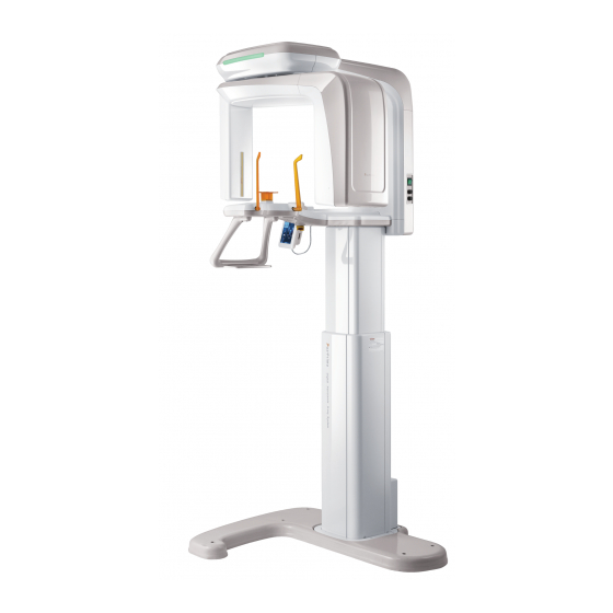
- Page 39 Please make sure that ground on which equipment is to be installed is flat and dry before installation. 1. Unpack the carton and locate two units ━ main unit and base plate. <PaX-Primo main unit> <base plate> 2. Unpack the carton and locate two units - main unit and base plate.
- Page 40 3. Please mount the system onto the base plate to assemble, as arrow indicated. 4. Please fix the main unit onto the base plate securely using the supplied M10*25(Accessory No.33X4) (Orange color) PaX-Primo...
- Page 41 5. Please install two base covers (Accessory No.12, 05) in a way that rear base cover first is installed and front base cover installed later ,so that the front base cover can be stacked onto the rear one.(See the colored parts) <Rear base cover>...
- Page 42 2. Fix the touch pad screen using M6*10 wrenches bolts (Accessory No.26x3) and from this step on, procedures are the same as those of installation on the PaX-Primo unit itself. PaX-Primo...
- Page 43 3. Remove two M4*8 truss bolts from the back of the touch pad panel using cross screw driver. 4. Please remove two plastic covers. Installation manual...
- Page 44 5. Please unscrew 4 M4*8 trusses bolt (Accessory No.14) and detach the touch pad screen from the holding arm. 6. Please connect both LAN cable (Acc. No.21) and RS-232(Acc. No.33) for touch pad screen onto connector panel of the underside of rear of unit. Connector panel PaX-Primo...
- Page 45 7. Please connect the LAN cable (Accessory No.36) to the connector on the underside of touch pad screen. And next connect this cable to the LAN port on the PC. 8. Please attach the touch pad screen bracket (Acc. No. 10) to the back of panel and screw it using M4*8 truss bolts.
- Page 46 9. Please first install truss bolts screw anchors on the wall (Accessory No.36) where the touch pad panel is to be installed. Mount the wall mount bracket (Acc. No.10) and fix it using M4*16(Accessory No.27x4). 10. Please align the wall bracket and that of touch pad panel PaX-Primo...
- Page 47 11. After completing attachment, it has been done. Installation manual...
- Page 48 1. First unscrew 4 M3*6 truss bolts and separate the bracket from the exposure switch holder. (Accessory No.09) 2. Please first install truss bolts screw anchors on the wall where the touch pad panel is to be installed. Mount the wall mount bracket (Acc. No.27) and fix it using M4*16(Accessory No.35x4). PaX-Primo...
- Page 49 3. Connect one end of exposure switch cable to the connector of the unit and the other end to A of switch holder and connect the exposure switch to SW on the underside of holder. Installation manual...
- Page 50 4. Please align both wall bracket and exposure switch holder and screw them using 4 M3*6 bolt supplied. 5. Now installation for the exposure switch holder has finished. PaX-Primo...
- Page 51 The following figure shows the whole system configuration of PaX-Primo. Installation manual...
- Page 52 PaX-Primo...
- Page 53 Exiting packing mode and finishing installation Important: PaX-primo has a unique feature, called packing mode, built in the system to prevent the unit from being damaged, which may be caused by the unexpected power supply to the unit while installing. Thus when shipped, it is in the packing mode by factory default.
- Page 54 1. Please focus on the setup.exe and double-click it. <For the first time installation> 2. The following screen will appear and click Next. Once this program has been installed previously on this same PC, you may have the following screen, indicating the default folder already created. PaX-Primo...
- Page 55 3. Please select the language from the group of radio buttons and then click Next. Installation manual...
- Page 56 4. From the next screen check the box to install the frame grabber driver, since the acquired data are transmitted to the PC via frame grabber card installed in the PC. 5. Make sure that the correct designation directory is created and click Next. PaX-Primo...
- Page 57 6. This is the last step before you can reconfigure the parameters or options by clicking the Back. Provided that you are convinced installation, click Install. 7. Now installation is in progress. Installation manual...
- Page 58 8. Upon finishing installation of PaX-Primo.exe, you are welcome to the frame grabber driver with the following screen. Click Next. 9. Make sure the destination folder and click Next. PaX-Primo...
- Page 59 10. This is the last step. By clicking installation it will proceed. 11. Now installing the driver. Installation manual...
- Page 60 12. Installation is complete and click Finish. 13. Rebooting the PC to take those configurations into effect. Check the radio button of Yes; I want to restart my computer now and click Finish. PaX-Primo...
- Page 61 <To reinstall the programs> 1. The initial screen after clicking the setup.exe looks like the following. Check the Modify radio button and Next. Installation manual...
- Page 62 2. Select the default and click Next. 3. The Modification is complete and click Finish. PaX-Primo...
- Page 63 <Performing the fine-tuning of parameters after completion of software installation> 1. Please run the EasyDent program. From the main window, click Pano icon on the upper left corner to call the imaging capture program. Then the following screen will appear. Installation manual...
- Page 64 2. Click on the upper right corner to invoke the following screen. Enter the password: “Vatech” in the lower case letters and click Login. 3. The following control panel will appear. From here you can configure various parameters to accommodate the requirements.
- Page 65 ⑥ Selecting the patient information file: displays the patient information. This is activated only when SDK Link is chosen for DB Link Type field. ⑦ User-defined location for image storage: The user can define where the acquired images can be saved in the formats of RAW and BMP. ⑧...
- Page 66 Check the radio button of “Use the following IP address” and enter the above address. By default it is 192.168.1.88 but it may be changed under some circumstances. And leave empty in the DNS server area. PaX-Primo...
- Page 67 <To remove the frame grabber driver from the PC> 1. Go to My computer → Control panel → Add/Remove programs. Locate the PaXPrimo_Ver1.0.0.5.2 and click Remove. Select Remove button and click Next. 2. The small warning screen will pop up and click Confirm. 3.
- Page 68 4. Removal process is finished and click Finish. 5. Make sure that the program has removed from the programs list. PaX-Primo...
- Page 69 Copyright by © 2009 Vatech The information in this document is subject to change without notice and does not represent a commitment on the part of the vendor, who assumes neither liability nor responsibility for any errors that may appear in this manual.
- Page 72 PaX-Primo...
Need help?
Do you have a question about the PaX-Primo and is the answer not in the manual?
Questions and answers