
Related Manuals for VeriFone P200


Summary of Contents for VeriFone P200
- Page 1 P200/P200 Plus Installation Guide Verifone Part Number DOC430-003-EN- , Revision B...
- Page 2 Verifone, Inc. The in formation cont ained in this d ocument is subj ect to chan ge wi thout notice. Alth ough Verifone ha s attempted to en sure the accuracy of the contents of this document, this document may include errors or omissions. The examples and sample programs are for illustration only and may not be suited for your purpose.
-
Page 3: Table Of Contents
P200 ............16 Connection to Another Verifone Terminal......16 RS-232 Connection Using an External Power Brick . - Page 4 Caution and Warning Messages ........35 P P E N D I X P200/P200 P NSTALLATION...
-
Page 5: Preface
REFACE This guide is the primary source of information for setting up and installing a P200 device. This guide provides simple descriptions of the P200 features, as well as basic Audience information for installing and configuring the P200. This guide is organized as follows:... -
Page 6: Guide Conventions
The pencil icon is used to RS-232-type devices do not work NOTE highlight important information. on the P200 communication port. The caution symbol indicates The unit is not waterproof or hardware or software failure, or dustproof, and is intended for CAUTION loss of data. - Page 7 REFACE Guide Conventions (continued) Table 2 Acronym Definitions Acronym Definitions Personal Identification Number Point-of-Sale RS-232 Recommend Standard number 232 Secure Access Module Underwriters Laboratories Universal Serial Bus Verifone Part Number P200/P200 P NSTALLATION UIDE...
- Page 8 REFACE Guide Conventions P200/P200 P NSTALLATION UIDE...
-
Page 9: Chapter P200
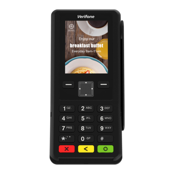
The P200 is a consumer facing handheld device. It can also be fix-mounted in some integrated retail scenarios. The product’s design is equally appealing as a handheld PINpad and robust enough to look and function appropriately in a fixed mount setting. -
Page 10: Back Functions
240 (RGB) x 320 TFT (QVGA) display. • Total memory of 384 MB (256 MB Flash and 128 MB DDR3) for P200, and • total memory of 1 GB (512 MB Flash and 512 MB DDR3) for P200 Plus. -
Page 11: Hapter
Do not use the P200 outdoors. • CAUTION The P200 is not waterproof or dustproof, and is intended for indoor use only. Any damage to the unit from exposure to rain or dust can void any warranty. P200/P200 P NSTALLATION... -
Page 12: Electrical Considerations
Avoid using this product during electrical storms. Electrical • Considerations Do not use the P200 unit near water or in moist conditions. • Disconnect the device from its POS terminal before cleaning. • Due to risk of electrical shock or terminal damage, do not use the terminal near... -
Page 13: Ensuring User Privacy
Carefully inspect the shipping carton and its contents for possible tampering or Unpacking damage. Shipping Carton Remove the P200 unit from the shipping carton. The standard package contains the PIN pad only and does not include any other cables or accessories. Refer to Accessories and Documentation for more information about P200-related accessories. -
Page 14: Msam/Usd Cards
Slide out and lift the compartment cover. The uSD and MSAM cardholders are now accessible. NOTE The P200 supports two MSAM cards in a stacked configuration. P200 Plus features a uSD connector. Install the uSD or MSAM card by carefully sliding it into the slot until fully inserted. -
Page 15: Power Supply
If no application is loaded, DOWNLOAD NEEDED appears on the display after the initial Verifone copyright screen. P200 can be powered with 5 V supply from USB port (5V at 500 mA) with the USB Power Supply following power-saving conditions controlled by OS: Maximum audio output volume is reduced. -
Page 16: Cable Connections
As soon as checkout is complete, the device exits CTLS payment mode and remains off until activated for the next checkout. The P200 has several cabling scenarios, depending on what it connects to: Cable Connections Connection to Another Verifone Terminal. - Page 17 • Configuration 2 - P200 to VX 520 Connect the 28-pin connector of the coiled serail cable (VPN - CBL282-036- 01-A) to P200, then insert the other end of the cable to the RS-232 port of VX 520. Figure 6...
- Page 18 USB Connection • Configuration 1 - P200 to V200c P200 can be powered up by V200c via the USB port. Connect the USB cable CBL282-038-xx-A directly to the USB1 (USB Vertical Type A) port of V200c. Figure 8 Connecting to V200c Via USB...
-
Page 19: Rs-232 Connection Using An External Power Brick
V200c. Figure 9 Connecting to V200c via Serial A special dongle cable is used, where one end of the cable plugs into the P200 RS-232 Connection while the other end terminates in a DB-9 connector housing. On the housing, a Using an External DC jack is provided to connect to an external power brick. -
Page 20: Direct Usb Connection
Powered USB instead of requiring an independent power supply or external AC adapter. Connection Connect the cable (VPN - CBL282-033-01-A) to the P200 and plug the male USB connector into the corresponding USB port of the connecting device. Figure 12 Connecting to USB-Based Host via Powered USB. -
Page 21: Ethernet Connection With External Power Brick
PINPad to LAN infrastructure), MOD-8 socket, Mini USB, type A USB & DC-in jack The figure below shows the connections available on the external power brick. Figure 13 Available Connections on the External Power Brick P200/P200 P NSTALLATION UIDE... -
Page 22: Smart Card Reader
Leave the smart card in the card reader until the transaction is completed. Premature removal can void the transaction. The P200 has a magnetic card reader that uses a triple track stripe reader. This Magnetic Stripe gives the unit greater reliability over a wide range of swipe speeds and operating Card Reader Use environments. -
Page 23: Contactless Transactions
Position a magnetic card with the stripe facing the keypad. Transaction Swipe it through the magnetic card reader. The P200 supports contactless transactions through an integrated contactless Contactless module. The terminal only becomes active for contactless smart card transactions Transactions when initialized by an application. - Page 24 Failure to use the privacy shield in PCI-compliant manner will void compliance for the affected device. Half-height Type - This privacy shield is not PCI-compliant. This may only be • used when P200 is mounted on a swivel stand. Figure 18 Half-height Type Privacy Shield To install a privacy shield:...
-
Page 25: Stylus And Holder
ETUP Optional Accessories A stylus with holder can be attached to P200 and used as an alternative device Stylus and Holder input method. To attach the stylus: Attaching the Stylus Holder Align the stylus holder’s screw holes with those found on the back of the terminal. -
Page 26: Periodic Inspection
If any device is found in tamper state, please remove it immediately from service. NOTE Keep it available for potential forensic investigation, and notify your company security officer and your local Verifone representative or service provider. For more information on contacting Verifone, refer to Service and Support. -
Page 27: Specifications
HAPTER Specifications This chapter discusses power requirements, dimensions, and other specifications of the P200 device. P200 and P200 Plus devices have the following power requirements: Unit Power Requirements 7-12 V DC, 1A Full capability: • Reduced capabilities (USB powered): 5 V DC, 500 mA •... -
Page 28: Sam Card Reader
PECIFICATIONS SAM Card Reader SAM Card Two Security Access Modules (SAMs) • Reader Security 3DES encryption, Master/Session and DUKPT key management • VeriShield file authentication • PCI PED 4.0 approved • P200/P200 P NSTALLATION UIDE... -
Page 29: Troubleshooting Guidelines
HAPTER Troubleshooting Guidelines This chapter lists typical malfunctions that may occur while operating a P200 device and the appropriate corrective action. If the problem persists – even after performing the outlined guidelines, or if the problem is not described, contact your local Verifone representative for assistance. - Page 30 ROUBLESHOOTING UIDELINES Transactions Fail To Process If the problem persists, contact your local Verifone representative. • Check Smart Card Reader Perform a test transaction using several different smart cards to ensure the • problem is not a defective card. Ensure that the card is inserted correctly (see Magnetic Stripe Card Reader •...
-
Page 31: Service And Support
Never use thinner, trichloroethylene, or ketone-based solvents – they can CAUTION deteriorate plastic or rubber parts. Because the P200 can be damaged by liquid, do not spray cleaners or other solutions directly onto the keypad or display. Always apply the cleaner to a cloth before cleaning the device. -
Page 32: Decommissioning/Removal From Service
You will be issued MRA number(s) and the fax will be returned to you. • NOTE One MRA number must be issued for each P200 unit you return to Verifone, even if you are returning several of the same model. Describe the problem(s). -
Page 33: Accessories And Documentation
Turn the device face up showing the display and keypad. Verify that the unit is in an “Active Tamper.” You should see the *TAMPER* message displayed on the screen. Verifone produces accessories and documentation for the P200. When ordering, Accessories and please refer to the part number in the left column. -
Page 34: Cables
ERVICE AND UPPORT Accessories and Documentation Contact your local Verifone distributor to determine which cable fits your needs. Cables CBL280-025-02-A USB Cable 4.1 m CBL282-045-XX-A USB cable (as Device). Powered from +9 V/1 A DC adaptor CBL282-038-XX-A USB cable (as Device). Powered from +5 V USB Host. -
Page 35: Appendix A Caution And Warning Messages
Cet appareil est un produit sûr et toute and any tampering can cause it to manipulation peut l'amener à cesser de cease to function or operate in an fonctionner ou fonctionner de manière non unsecured manner. sécurisée. P200/P200 P NSTALLATION UIDE... - Page 36 être endommagé, en label. If a label or component aviser immédiatement la compagnie maritime appears damaged, immediately et votre représentant Verifone ou prestataire notify the shipping company and de services. your Verifone representative or service provider.
- Page 37 Toujours directly onto the keypad or appliquer le nettoyant sur un chiffon avant de display. Always apply the cleaner nettoyer l'appareil. to a cloth before cleaning the device. P200/P200 P NSTALLATION UIDE...
- Page 38 Verifone, Inc. 1-800-Verifone www.verifone.com P200/P200 Plus Installation Guide Verifone Part Number DOC430-003-EN-B, Revision B...
Need help?
Do you have a question about the P200 and is the answer not in the manual?
Questions and answers