Table of Contents
Advertisement
Available languages
Available languages
Quick Links
Advertisement
Table of Contents

Related Manuals for emmeti X-REVO-19C Series


Summary of Contents for emmeti X-REVO-19C Series
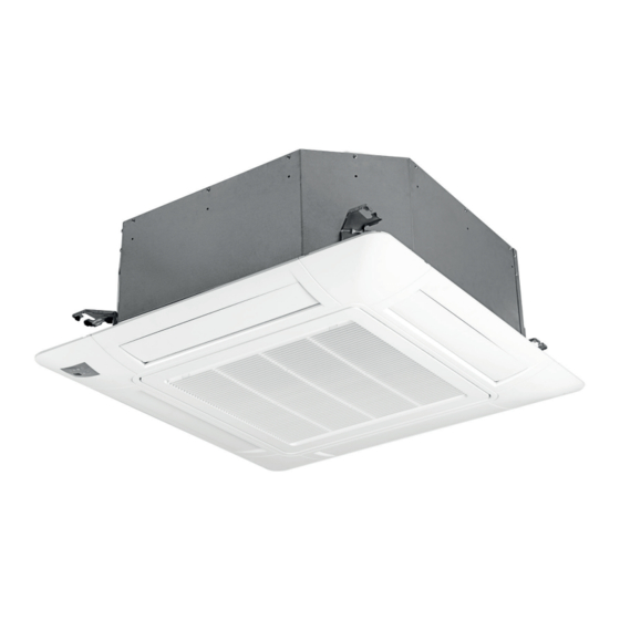
- Page 1 Air Conditioners Serie: X-REVO-XX19C CASSETTE IT IT MANUALE INSTALLAZIONE ED ISTRUZIONI PER L’USO MANUALE INSTALLAZIONE ED ISTRUZIONI PER L’USO USE AND INSTALLATION MANUAL USE AND INSTALLATION MANUAL...
- Page 2 IT IT IT IT pagina 4 page 47 Vi ringraziamo per la fiducia concessaci nell’acquisto di questo prodotto. Thanks you for the trust you have shown by purchasing this produtc. Vi invitiamo a leggere attentamente questo manuale dove sono riportate Carefully read this manual which contains the specifications and all the le caratteristiche tecniche e tutte le informazioni utili per ottenere un information useful for the correct functioning.
- Page 3 IT IT 1. DESCRIZIONE DEI COMPONENTI INDICE 1. PRESENTAZIONE DEL PRODOTTO ..4 7. USO DEL TELECOMANDO AD INFRAROSSI ......19 1.1 Introduzione alla climatizzazione 7.1 Telecomando 1.2 Il circuito frigorifero 7.2 Funzionamento in ventilazione FAN ONLY 1.3 Composizione del climatizzatore 7.3 Funzionamento in raffreddamento COOL 1.4 Unità...
- Page 4 IT IT 1. DESCRIZIONE DEI COMPONENTI 1. PRESENTAZIONE DEL PRODOTTO 1.1 Introduzione alla climatizzazione 1.3 Composizione del climatizzatore La funzione dei climatizzatori è quella di creare, negli ambienti in cui sono I climatizzatori sono della tipologia “Split System” con scambio termico installati, le condizioni ottimali di temperatura e di umidità...
- Page 5 IT IT 1. DESCRIZIONE DEI COMPONENTI 1. PRESENTAZIONE DEL PRODOTTO 1.6 Accessori forniti in dotazione all'unità interna 1.7 Tabella identificazione prodotti La seguente tabella serve ad identificare il climatizzatore completo Accessori forniti in dotazione: o la singola unità acquistata: X-REVO-XX19C Q.ta Descrizione Tipo...
- Page 6 IT IT 1. DESCRIZIONE DEI COMPONENTI 2. AVVERTENZE Significato dei simboli 2.1 Attenzioni e pericoli Prima di continuare le operazioni leggere il manuale per l'operatore Prima di utilizzare il climatizzatore leggere attentamente il presente Prima di eseguire interventi di manutenzione e riparazione, manuale di istruzioni.
- Page 7 IT IT 1. DESCRIZIONE DEI COMPONENTI 2. AVVERTENZE Qualora si verifichi un malfunzionamento è consigliabile spegnere prima Utilizzare il climatizzatore solo per cli- il condizionatore col telecomando, prima di scollegare l'alimentazione matizzare il locale. elettrica. Non usare il condizionatore per altri scopi, es.
-
Page 8: Descrizione Dei Componenti
IT IT 1. DESCRIZIONE DEI COMPONENTI 3. INFORMAZIONI IMPORTANTI 3.1 Conformità ai regolamenti 3.2 Grado di protezione degli involucri (Codice IP) I climatizzatori sono conformi alle direttive europee: 2014/30/UE relativa alla compatibilità elettromagnetica IPXO Unità interna 2014/35/UE relativa alla bassa tensione = Grado di protezione contro la perforazione dei corpi solidi 2012/19/CE RAEE riguardante i rifiuti di apparecchiature elettriche ed esterni é... - Page 9 IT IT 1. DESCRIZIONE DEI COMPONENTI 3. INFORMAZIONI IMPORTANTI 3.4 Estratto della scheda di sicurezza refrigerante R 32 Gas refrigerante Tipo R 32 Denominazione Difluorometano 3.0 H220: Gas altamente infiammabile. Indicazioni dei pericoli H280: Contiene gas sotto pressione; può esplodere se riscaldato. DESCRIZIONE DELLE MISURE DI PRIMO SOCCORSO In alta concentrazione può...
- Page 10 IT IT 1. DESCRIZIONE DEI COMPONENTI 3. INFORMAZIONI IMPORTANTI PROPRIETÀ FISICHE E CHIMICHE Informazioni sulle proprietà fisiche e chimiche fondamentali Forma Forma Gas liquefatto Colore Incolore Odore Odore di etere Punto di ebollizione -51,6 °C (101,325 kPa) Densità relativa 1,1 (Materiale di riferimento: Acqua) Solubilità...
-
Page 11: Movimentazione E Trasporto
IT IT 4. MOVIMENTAZIONE E TRASPORTO Movimentazione di unità pesanti Disimballo Le operazioni di disimballo devono essere eseguite con cura, al fine di non danneggiare l’involucro delle unità, se si opera con coltelli o taglierini per aprire l’imballo in cartone. ATTENZIONE Dopo aver tolto l’imballo assicurarsi dell’integrità... -
Page 12: Posizionamento Dell'unità
IT IT 5. POSIZIONAMENTO DELL'UNITÀ (e) In veicoli o imbarcazioni. Il condizionatore deve essere collocato in un luogo ben ventilato e facilmente (f) In cucine con molti fumi di oli ed alta percentuale d’ umidità. accessibile. (g) Vicino a macchine che emettono onde elettromagnetiche. Il condizionatore non deve essere collocato nei luoghi che seguono: (h) Luoghi con fumi acidi o alcalini. - Page 13 IT IT 5. POSIZIONAMENTO DELL'UNITÀ 1. DESCRIZIONE DEI COMPONENTI 5.2 Distanze minime funzionali unità interna Soffitto Modello H (mm) >20 X-REVO-1219C X-REVO-1819C Parete Parete ≥1500 ≥1500 Dimensioni in mm Pavimento 5.3 Dati dimensionali unità interna Uscita aria Uscita aria Entrata aria Tubo Gas Tubo liquido refrigerante...
-
Page 14: Installazione Dell'unità Interna
- Per eventuali riparazioni contattare il Servizio Assistenza. Le riparazioni di carattere elettrico devono essere eseguite da elettricisti qualificati. - Operazioni non adeguate possono provocare gravi danni all'utente. - La lista dei centri assistenza è disponibile nel sito web www.emmeti.com. La corretta installazione del climatizzatore ne garantisce l’efficiente funzionamento. -
Page 15: Unità Interna
1-1.5m 1-1.5m IT IT 1. DESCRIZIONE DEI COMPONENTI 6. INSTALLAZIONE DELL'UNITÀ INTERNA - Dopo l’installazione sul soffitto, regolare l’apparecchio nella posizione Fascetta stringi tubo corretta e controllare che il corpo dell’apparecchio sia a livello. 1-1.5m 1-1.5m Nota: L’unità interna contiene una pompa a scarico condensa ed un interruttore Raccordo scarico CORRETTO Nastro adesivo... - Page 16 IT IT 6. INSTALLAZIONE DELL'UNITÀ INTERNA Isolamento delle tubazioni 6.4 Tubazioni circuito frigorifero Prima di eseguire le operazioni di cartellatura del tubo è indispensabile Le connessioni per le tubazioni frigorifere sono con tenuta a cartella e isolarlo e poi inserire i bocchettoni sul tubo. bocchettone.
-
Page 17: Allacciamento Elettrico
IT IT 6. INSTALLAZIONE DELL'UNITÀ INTERNA Connessione dei tubi ai raccordi Alimentazione delle unità Connettere le tubazioni ai raccordi delle unità. L'alimentazione viene portata sull' unità esterna. Per il serraggio stringere i bocchettoni con una coppia pari a: Utilizzare una fonte di alimentazione ad uso esclusivo del climatizzatore, con interruttore magnetotermico/differenziale dedicato. - Page 18 IT IT 6. INSTALLAZIONE DELL'UNITÀ INTERNA Nastratura alluminata Tubazioni frigorifere Scarico condensa unità interna Cavo elettrico di collegamento tra le unità - Prevedere l’uso di una guaina di protezione dei cavi esposti all’esterno. - È consigliabile predisporre i cavi con un percorso antigoccia onde evitare possibili infiltrazioni d’acqua nell’unità...
- Page 19 Premendo questo pulsante, tutte le QUIET visualizzazioni relative all’unità Per impostare o annullare la interna saranno disattivate. Premere modalità Silenzioso. un tasto qualsiasi per ripristinarle. Avvertenza: Il telecomando IR X-REVO IR1 è compatibile solo con i condizionatori d’aria della linea X-REVO EMMETI.
- Page 20 IT IT 7. USO DEL TELECOMANDO AD INFRAROSSI Simboli delle indicazioni sul display LCD: Indicatore di Indicatore Modalità sleep1 Indicatore della modalità super raffreddamento Ifeel Indicatore del Indicatore Modalità sleep2 deumidificatore Trasmissione del segnale Indicatore di Indicatore Modalità sleep3 funzionamento esclusivo Indicatore di carica della batteria del ventilatore Indicatore del...
- Page 21 IT IT 7. USO DEL TELECOMANDO AD INFRAROSSI Come inserire le batterie Come usare il telecomando e avviare il climatizzatore 1 - Aprire il coperchio del vano della batteria Per utilizzare il condizionatore indirizzare il telecomando verso osservando la direzione della freccia. il ricevitore del segnale.
-
Page 22: Fan Speed
IT IT 7. USO DEL TELECOMANDO AD INFRAROSSI Attenzione Modelli: Dual / Trial / Quadrial A salvaguardia del corretto funzionamento del compres- Le unità interne devono essere poste in funzione tutte sore è previsto che nella medesima modalità di funzionamento o in modali- - Una volta arrestato, non potrà... - Page 23 IT IT 7. USO DEL TELECOMANDO AD INFRAROSSI 7.3 Funzionamento 7.4 Funzionamento in riscaldamento HEAT in raffreddamento COOL Premendo il pulsante MODE selezionare il modo Premendo il pulsante MODE selezionare il modo di di funzionamento COOL funzionamento HEAT Con i pulsanti TEMP impostare TEMP impostare la...
-
Page 24: Funzionamento In Automatico
IT IT 7. USO DEL TELECOMANDO AD INFRAROSSI Sbrinamento automatico regolato dal microprocessore damente l’operazione di sbrinamento (di durata compre- rapi - Quando il climatizzatore viene utilizzato in modo sa tra 2 e 10 minuti). Nelle unità interne che lo prevedono, si accende e/o lampeggia un apposito simbolo sul display (vedere Riscaldamento in condizioni esterne di bassa temperatura il manuale delle unità... -
Page 25: Regolazione Della Direzione Del Flusso Dell'aria
IT IT 7. USO DEL TELECOMANDO AD INFRAROSSI 3 Premendo il pulsante selezionare la posizione dei deflettori desiderata. 4 Premendo il pulsante FAN SPEED selezionare la velocità desiderata del ventilatore Alta Media Automatica Bassa Il pulsante SMART non funziona nella modalità SUPER. Il pulsante ECONOMY non funziona nella modalità... - Page 26 IT IT 7. USO DEL TELECOMANDO AD INFRAROSSI Controllo del FLUSSO D’ARIA VERTICALE (con il telecomando) Con il telecomando è possibile definire l’angolazione del flusso d’aria desiderata. Premendo il pulsante Risultato: Il deflettore del flusso d’aria oscillerà automatica- verticale mente versol’alto e verso il basso 2 Premendo di nuovo il pulsante Il deflettore rimane fisso nella posizione desiderata.
- Page 27 IT IT 7. USO DEL TELECOMANDO AD INFRAROSSI 7.9 Programmazione del Timer Accensione programma del climatizzatore Premere il pulsante una volta Risultato: ON 12:00 lampeggia sul display. 2 Premere i pulsanti Risultato: Aumento o diminuzione di 1 minuto ad ogni pressione del pulsante.
-
Page 28: Funzione Sleep
IT IT 7. USO DEL TELECOMANDO AD INFRAROSSI 7.10 Funzione SLEEP Premere il pulsante più volte per selezionare una delle seguenti opzioni MODALITÀ SLEEP 1 Raffreddamento Riscaldamento Tamb Tamb Tset Tset +2 Tset Tset -2 Time [h] Time [h] MODALITÀ... - Page 29 Tset -2 Tset IT IT 7. USO DEL TELECOMANDO AD INFRAROSSI Time [h] Time [h] MODALITÀ SLEEP 3 Raffreddamento Riscaldamento Tamb Tamb Tset Tset+3 Tset -2 Tset+1 Tset -4 Tset Time [h] Time [h] MODALITÀ SLEEP 4 Raffreddamento Riscaldamento Tamb Tamb Tset Tset...
-
Page 30: Funzione Super
IT IT 7. USO DEL TELECOMANDO AD INFRAROSSI 7.11 Funzione SUPER La modalità SUPER viene utilizzata per avviare o interrom- pere il raffreddamento o il riscaldamento rapido. Nella modalità SUPER, l’indicatore super verrà visualizzato sullo schermo LCD. La modalità SUPER può essere impostata quando l’appa- recchio è... -
Page 31: Funzione Ifeel
IT IT 7. USO DEL TELECOMANDO AD INFRAROSSI 7.13 Funzione ECONOMY In questa modalità, il condizionatore funzionerà a basso consumo energetico impostando automaticamente la velocità del ventilatore al minimo e le seguenti temperature di Set: - Selezionando il tasto economy dalla modalità raffredamento: Tset = 24 °C - Selezionando il tasto economy dalla modalità... -
Page 32: Funzione Dimmer
IT IT 7. USO DEL TELECOMANDO AD INFRAROSSI 7.15 Funzione DIMMER Premere sul telecomando il pulsante DIMMER per accendere o spegne- re il display e le spie sul pannello frontale. Valido per le unità interne dotate di Display) 7.16 Funzione BLOCCO TASTI Per bloccare la tastiera premere ‘TIMER OFF’... - Page 33 IT IT 8. USO DEL CLIMATIZZATORE 1. DESCRIZIONE DEI COMPONENTI Per un uso corretto del climatizzatore Impostare la temperatura ambiente in modo adeguato. Non collocare ostacoli davanti alle griglie di aspirazione e di uscita. Temperatura adeguata Chiudere porte e finestre durante il funzionamento In modalità Utilizzare il Timer in maniera efficace.
-
Page 34: Pulizia Del Telecomando
IT IT 9. MANUTENZIONE DEL CLIMATIZZATORE Attenzione! Tutte le operazioni di manutenzione devono essere eseguite dopo aver tolto l’alimentazione elettrica al climatizzatore. 9.1 Pulizia del telecomando - Per pulire il telecomando utilizzare un panno asciutto, non utilizzate prodotti per la pulizia dei vetri o detergenti. 9.2 Pulizia dell’unità... -
Page 35: Manutenzione Straordinaria
IT IT 9. MANUTENZIONE DEL CLIMATIZZATORE 9.4 Verifica dello scarico In caso di inutilizzo del climatizzatore per un lungo periodo, scol- legare l'apparecchiatura dall'alimentazione. dell’acqua di condensa ATT EN ZI O N E Nell’uso estivo del climatizzatore verificare il corretto drenaggio dell’ac- qua di condensazione dall’unità... -
Page 36: Pulizia Del Filtro
IT IT 1. DESCRIZIONE DEI COMPONENTI 9. MANUTENZIONE DEL CLIMATIZZATORE 9.8 Pulizia del filtro Non azionare il sistema senza filtro dell'aria per proteggere lo scambiatore di calore dell'unità interna contro i rischi di intasamento. SPEGNERE l'interruttore principale prima di smontare il filtro. Quando l'indicatore "Filtro"... -
Page 37: Anomalie Di Funzionamento
IT IT 10. ANOMALIE DI FUNZIONAMENTO In particolari condizioni il climatizzatore può presentare anomalie di funzionamento che spesso sono apparenti o determinate da cause accidentali o, più spesso, banali. Attenzione! Prima di richiedere l’intervento del centro assistenza è consigliabile eseguire facili controlli sia per usufruire in continuazione e al meglio delle prestazioni del climatizzatore, sia per evitare inutili interventi di assistenza. - Page 38 IT IT 10. ANOMALIE DI FUNZIONAMENTO 10.1 Segnalazioni visualizzate sul display dell'unità interna I codici di errore vengono segnalati dal numero di lampeggi delle seguenti spie LED presenti sul display dell’unità: 1) Indicatore di funzionamento RUN (LED2, rosso) 2) Indicatore di sbrinamento DEFROST (LED5, verde), Il numero di lampeggi dell’indicatore di funzionamento (RUN) indica il decimale;...
- Page 39 IT IT 10. ANOMALIE DI FUNZIONAMENTO Codice di Descrizione Errore Possibili Cause Cosa fare Errore Errore Dati EEPROM interna 1 1.I Componenti EE interni sono difettosi; Sostituire la scheda di controllo dell'unità interna 2.Il circuito di controllo dei componenti EE è guasto;...
- Page 40 IT IT 1. DESCRIZIONE DEI COMPONENTI 12. SMALTIMENTO 12.1 Nota informativa RAEE 12.3 Norme di smaltimento dell'imballaggio del Ai sensi dell’art. 26 del Decreto Legislativo 14 marzo 2014, n. 49 nuovo climatizzatore “Attuazione della Direttiva 2012/19/UE sui rifiuti di apparecchia- ture elettriche ed elettroniche (RAEE)”.
-
Page 41: Schemi Elettrici
IT IT 1. DESCRIZIONE DEI COMPONENTI 13. SCHEMI ELETTRICI E CONNESSIONI 13.1 Schemi elettrici: Modello X-REVO-1219C Legenda GB Legenda IT TERMINAL PANEL Morsettiera unità interna COIL TEMP. or COIL or T-COIL Sensore teperatura batteria scambio BLU or BU Colore blu DISCHARGE TEMP. -
Page 42: Terminal Panel
IT IT 1. DESCRIZIONE DEI COMPONENTI 13. SCHEMI ELETTRICI E CONNESSIONI Modello X-REVO-1819C Legenda GB Legenda IT TERMINAL PANEL Morsettiera unità interna COIL TEMP. or COIL or T-COIL Sensore teperatura batteria scambio BLU or BU Colore blu DISCHARGE TEMP. or DIS or T-DISS Sensore temperatura di scarico BLK or BK Colore nero... - Page 43 IT IT 13. SCHEMI ELETTRICI E CONNESSIONI 13.2 Installazione modulo Wifi 13.3 Ingresso "contatto finestra/presenza" E' possibile gestire le principali funzioni del climatizzatore dal proprio E' possibile collegare un "contatto finestra" o "sensore di presenza" per smartphone o tablet utilizzando l'App gratuita Smart-Living. inibire il funzionamento del climatizzatore quando la finestra è...
- Page 44 IT IT 13. SCHEMI ELETTRICI E CONNESSIONI Parametro 25 CONTATTO FINESTRA / PRESENZA Controllo a filo Bianco 2 Bianco 2 Bianco 3 (impostazione di fabbrica) Bianco 3 Unità in Stand-by L’unità si spegne (si può accendere solo con il telecomando/controllo a filo) Bianco 2 Bianco 2 Bianco 3...
-
Page 45: Condizioni Di Garanzia
Dichiara inoltre di aver preso visione della Informativa sui dati personali disponibile anche sul sito internet di Emmeti S.p.A. EMMETI spa - Via brigata Osoppo, 166 - 33074 Vigonovo frazione di Fontanafredda (PN) - Italia - Tel.0434567911 - Fax 0434567901 - www.emmeti.com... - Page 47 1. DESCRIZIONE DEI COMPONENTI INDEX 1. INTRODUCTION TO THE PRODUCT ..48 8. AIR CONDITIONER USE .......77 1.1 Introduction to the conditioning 9. AIR CONDITIONER MAINTENANCE ..78 1.2 Refrigeration circuit 1.3 Air conditioner composition 9.1 Remote control cleaning 1.4 Indoor unit 9.2 Indoor Unit cleaning 1.5 Buttons and lights of the indoor unit 9.3 External unit cleaning...
-
Page 48: Refrigeration Circuit
1. DESCRIZIONE DEI COMPONENTI 1. INTRODUCTION TO THE PRODUCT 1.1 Introduction to conditioning 1.3 Air conditioner composition Air conditioner function is to create perfect temperature and humidity Air conditioners are “Split System” type with air to air heat exchange conditions in the rooms they are installed, optimal conditions are able to They are composed of two separate units: satisfy human exigencies, in one word “comfort”. -
Page 49: Accessories Supplied With The Indoor Unit
1. DESCRIZIONE DEI COMPONENTI 1. INTRODUCTION TO THE PRODUCT 1.6 Accessories supplied with the indoor unit 1.7 Product identification table Through the following table you may identify the set model or the model of the single unit of the air conditioner. X-REVO-XX19C Q.ta Description... -
Page 50: Descrizione Dei Componenti
1. DESCRIZIONE DEI COMPONENTI 2. WARNINGS Attention and dangers Meaning of the symbols Before continuing the operations, read the operator manual Before using the air conditioner please read carefully the instructions ma- nual. Producer decline every responsibility for any damage caused by the Before doing any maintenance and repair works, read non-observing of the following warnings. - Page 51 1. DESCRIZIONE DEI COMPONENTI 2. WARNINGS Use the air conditioner only to If a device malfunction occurs, it is advisable to switch off the air condi- tioner through its remote control, before disconnecting the power supply. condition the room. Do not use the air conditioner for other purposes, for example: drying laundry, preserving food, breeding animals or cultivating...
- Page 52 1. DESCRIZIONE DEI COMPONENTI 3. IMPORTANT INFORMATION 3.1 Compliance with the regulations 3.2 Degree of protection provided by enclosures (IP Code) Air conditioners are conform to the European stadanrd: Indoor Unit 2014/30/EU regarding Electromagnetic Compatibility IPX0 2014/35/EU standards on Low Voltage. In accordance with the directive 2012/19/EC WEE of the European par- = Degree of protection against the perforation of solid bedies external is liament, herewith we inform the users about the disposal requirements...
-
Page 53: Refrigerant Gas
1. DESCRIZIONE DEI COMPONENTI 3. IMPORTANT INFORMATION 3.4 Extract from refrigerant gas R 32 safety data sheet Refrigerant gas R 32 Type Product Name Difluorometano 3.0 H220: Highly flammable gas. Physical hazards H280: It contains gas under pressure; it may explode when heated. FIRST AID MEASURES: In high concentrations, it may cause asphyxiation. - Page 54 1. DESCRIZIONE DEI COMPONENTI 3. IMPORTANT INFORMATION PHYSICAL AND CHEMICAL PROPERTIES Information on main physical and chemical properties Form Form Liquefed Gas Colour Colourless Odour Smell of ether Boiling Point -51,6 °C (101,325 kPa) Relative Density 1,1 (Reference) Solubility in water 280 g/l STABILITY AND RECTIVITY Chemical stability...
-
Page 55: Handling And Transport
4. HANDLING AND TRANSPORT Handling of heavy units Unpacking Unpacking operations have to be done carefully because the outdoor part of the units has not to be damaged when knifes or cutters are used to open the carton package. ATTENTION After unpacking make sure of the unit integrity. -
Page 56: Unit Positioning
5. UNIT POSITIONING f) In kitchens with a lot of oil fumes and with high humidity percentage Air conditioner has to be placed in a well-ventilated and easy to reach place. g) Near machines issuing electromagnetic waves Air conditioner has not to be placed in the following places: h) Places with acid or alkaline fumes a) Places where there are machines oils or other oils fumes. - Page 57 5. UNIT POSITIONING 1. DESCRIZIONE DEI COMPONENTI 5.2 Minimum functional distances Ceiling Model H (mm) X-REVO-1219C X-REVO-1819C Wall Wall 1500 1500 Dimension in mm Floor 5.3 Dimensional data of the indoor unit Air outlet Air outlet Air inlet Gas Pipe Liquid tube refrigerant refrigerant...
-
Page 58: Installation Of The Indoor Unit
- Repairs of an electrical nature must be performed by qualified electricians. - Improper operations may cause serious harm to the user. - You can find a list of service centres at the website www.emmeti.com The correct installation of the air conditioner guarantees its efficient operation. - Page 59 1-1.5m 1. DESCRIZIONE DEI COMPONENTI 6. INSTALLATION OF THE INDOOR UNIT Hose clamp - After the installation on the ceiling, adjust the unit on the right position and control it is at the level. 1-1.5m 1-1.5m Nota: Condensation discharge Adhesive tape The indoor unit includes a condensation drain pump and one float switch, fitting CORRECT...
-
Page 60: Refrigerating Circuit Piping
6. INSTALLATION OF THE INDOOR UNIT Insulating the pipelines 6.4 Refrigerating circuit piping - Before carrying out the flaring of the pipe, it is essential to insulate the The connections for the refrigerating piping are sealed with a flared end pipe and then fit the nuts on the pipe. -
Page 61: Electrical Supply
6. INSTALLATION OF THE INDOOR UNIT Connecting the pipes to the fittings Unit power supply - Connect the pipes to the fittings on the unit. The power is brought on the outdoor unit. -Secure by tightening the nuts to a torque of: Use a power source for the exclusive use of the air conditioner, with dedicated magnetothermal / differential switch. - Page 62 6. INSTALLATION OF THE INDOOR UNIT Aluminized tape Refrigeration piping Indoor unit condensation drain Electrical connection cable between the units - Provide to use a protection sheet for the cables exposed to the outside. - It is recommended to set the cables with a drip-proof run in order to avoid possible infiltrations of water in the outdoor unit.
-
Page 63: Infrared Remote Control
7. INFRARED REMOTE CONTROL 7.1 Infrared remote control This remote control unit transmits control signals to the system. TEMP SMART To adjust the room temperature and To start the automatic mode selection the timer, in addition to the current time. POWER MODE This button starts the appliance operation,... - Page 64 7. INFRARED REMOTE CONTROL Symbols on the display LCD Cooling indicator Sleep mode 1 indicator Super mode indicator Ifeel Sleep mode 2 indicator Dehumidifier indicator Signal trasmission Indicator Sleep mode 3 indicator of exclusive fan operation battery charge indicator Sleep mode 4 indicator Heating indicator Timer setting display of the current time O F F...
- Page 65 7. INFRARED REMOTE CONTROL How to use the remote control and start the air conditioner How to insert batteries To use the air conditioner, direct the remote control toward the signal 1 - Open the battery compartment cover observing the direction receiver.
- Page 66 7. INFRARED REMOTE CONTROL Models: Dual / Trial / Quadrial Attention The indoor units must be put into service in the same operational mode In order to safeguard the proper functioning of the compressor, it is or in compatibility mode according to the table below foreseen that Cooling Heating...
- Page 67 7. INFRARED REMOTE CONTROL 7.4 Heating functioning HEAT 7.3 Cooling functioning COOL Press the MODE key to select functioning HEAT Press the MODE key to select the functioning COOL With buttons TEMP set the desired temperature in the room (16 ÷...
- Page 68 7. INFRARED REMOTE CONTROL Attention: Automatic defrosting controlled by the microprocessor During defrosting, indoor and Outdoor Unit fans stop and some vapour of - When air conditioner is used in Heating mode and the temperature the Outdoor Unit can get out. This is due to the defrosting and not to a outside is low and humidity is high, dew accumulates on the Outdoor bad functioning Unit which reduces air conditioner performances.
-
Page 69: Adjusting The Direction Of Air Flow
7. INFRARED REMOTE CONTROL 3 By pressing button, select the deflectors desired position 4 Press Button FAN SPEED select the desired speed fan Automatic High Average The SMART button does not work in SUPER mode. The ECONOMY button does not work in SMART mode. 7.7 Adjusting the direction of air flow The vertical flow (horizontal flow) is automatically adjusted to the set mode:... - Page 70 7. INFRARED REMOTE CONTROL Checking the VERTICAL AIR FLOW (with the remote control) With the remote control you can set the desired airflow angle. Pressing the button The vertical air flow deflector will automatically swing up and down. 2 Pressing the button again The deflector remains fixed in the desired position Never start the vertical deflector by hand, otherwise it might malfunction.
-
Page 71: Programming The Timer
7. INFRARED REMOTE CONTROL 7.9 Programming the Timer Switch on the air conditioner program Press button once Result: ON 12:00 flashes on the display. 2 Press the buttons Result: 1 minute Increase or decrease every time you press the button. By pressing the button for a second and a half time increases or decreases by 10 minutes. -
Page 72: Mode Sleep
7. INFRARED REMOTE CONTROL 7.10 Funnction SLEEP Press the button repeatedly to select one of the following options TO EXIT Mode SLEEP4 Mode SLEEP1 Mode SLEEP2 Mode SLEEP3 SLEEP MODE MODE SLEEP 1 Cooling Heating Tamb Tamb Tset Tset +2 Tset Tset -2 Time [h]... - Page 73 Tset -1 Tset +1 Tset -2 Tset 7. INFRARED REMOTE CONTROL Time [h] Time [h] MODE SLEEP 3 Cooling Heating Tamb Tamb Tset Tset+3 Tset -2 Tset+1 Tset -4 Tset Time [h] Time [h] MODE SLEEP 4 Cooling Heating Tamb Tamb Tset Tset...
- Page 74 7. INFRARED REMOTE CONTROL 7.11 Function SUPER The SUPER mode is used to start or stop the cooling or the rapid heating. In the SUPER mode, indicator super will be displayed on the LCD screen. The SUPER mode can be set when the appliance is operating or connected to power.
- Page 75 7. INFRARED REMOTE CONTROL 7.13 Function ECONOMY In this mode, the air conditioner will operate at low power consumption. ECONOMY button is ineffective in SMART and SUPER mode. Press one of the ON/OFF, MODE, TEMP , TEMP FAN , SLEEP, QUITE or ECONOMY buttons to delete the ECONOMY mode. 7.14 Function iFEEL The temperature sensor incorporated into the remote control is activated.
-
Page 76: Auto Restart Function
7. INFRARED REMOTE CONTROL 7.15 Function DIMMER Press the DIMMER button on the remote control to switch the display and the front panel lights on or off. 7.16 KEY LOCK function To lock the keypad press ‘TIMER OFF’ for 3 seconds, then release, the symbol appears on the display. - Page 77 8. AIR CONDITIONER USE 1. DESCRIZIONE DEI COMPONENTI For correct use of the air conditioner Set the room temperature suitably. Do not place obstacles from in front of the intake and outlet grilles Suitable temperature Close doors and windows during operation in Cooling mode Use the Timer effectively In cooling mode, keep direct sunlight out...
-
Page 78: Indoor Unit Cleaning
9. AIR CONDITIONER MAINTENTANCE Attention! All maintenance operations must be carried out after having disconnected the power supply from the air conditioner. Turn off the air conditioner first with the remote control and then disconnect the power supply. 9.1 Remote control cleaning - To clean the remote control, use a dry cloth. -
Page 79: Extraordinary Maintenance
9. AIR CONDITIONER MAINTENTANCE 9.4 Condensate water drain check Maintenance Method When air conditioner won’t be used for a long time, please cut off the main power supply of air conditioner. When using the air conditioner in the summer time check that the conden- sation water is drained correctly from the indoor unit. -
Page 80: Cleaning The Filter
1. DESCRIZIONE DEI COMPONENTI 9. AIR CONDITIONER MAINTENTANCE 9.8 Cleaning the filter Do not operate the system without air filter to protect the heat exchanger of the indoor unit against the risk of clogging. TURN OFF the main switch before removing the filter. When the "Filter"... - Page 81 10. ANOMALIES AND FUNCTIONING In particular conditions the air conditioner may malfunction, this is often apparently or determined by accidental or, more often, banal causes. Attention! Before requesting the intervention of the service centre is recommended to perform easy checks for both to enjoy the air conditioner continuously and at best of its performances, in order to avoid unnecessary servicing.
- Page 82 10. ANOMALIES AND FUNCTIONING 10.1 Error codes displayed on Wire control display Error codes are indicated by the number of flashes of the following LED lights on the unit display: 1) RUN operation indicator (LED2, red) 2) DEFROST defrost indicator (LED5, green), The number of flashes of the operation indicator (RUN) indicates the decimal;...
- Page 83 10. ANOMALIES AND FUNCTIONING Error Description Causes How to Deal With code FE (254) Communication 1. The wiring between the wiring controller to the 1.Reconnect the wiring between the wiring controller to between main indoor control board connect loose; the indoor control board; control board 2.
-
Page 84: Battery Disposal
1. DESCRIZIONE DEI COMPONENTI 11. DISPOSAL 11.3 Disposal rules for the new air conditioner 11.1 INFORMATION NOTE WEEE packaging Directive 2012/19 / EU All of the air conditioner packing materials can be disposed of without harming the environment. The cardboard box must be cut into pieces and delivered to a paper collection container. -
Page 85: Electrical Wiring Diagram
1. DESCRIZIONE DEI COMPONENTI 12. ELECTRICAL DIAGRAMS AND CONNECTIONS 12.1 Electrical wiring diagram Model X-REVO-1219C Legenda GB Legenda IT TERMINAL PANEL Morsettiera unità interna COIL TEMP. or COIL or T-COIL Sensore teperatura batteria scambio BLU or BU Colore blu DISCHARGE TEMP. or DIS or T-DISS Sensore temperatura di scarico BLK or BK Colore nero... - Page 86 1. DESCRIZIONE DEI COMPONENTI 12. ELECTRICAL DIAGRAMS AND CONNECTIONS 12.2 Electrical wiring diagram Model X-REVO-1819C Legenda GB Legenda IT TERMINAL PANEL Morsettiera unità interna COIL TEMP. or COIL or T-COIL Sensore teperatura batteria scambio BLU or BU Colore blu DISCHARGE TEMP. or DIS or T-DISS Sensore temperatura di scarico BLK or BK Colore nero...
- Page 87 12. ELECTRICAL DIAGRAMS AND CONNECTIONSESSIONI 12.4 “Window / presence contact” input 12.3 Wifi module installation It is possible to connect a “window contact” or “presence sensor” to inhibit It is possible to manage the main functions of the air conditioner from your the operation of the air conditioner when the window is open or the room smartphone or tablet using the free Smart-Living App.
- Page 88 12. ELECTRICAL DIAGRAMS AND CONNECTIONS Parameter 25 CONTACT WINDOW / PRESENCE Wired control White 2 White 2 White 3 (factory setting) White 3 Unit is in stand-by The unit turns off (can be turned on only trough IR control/wired control) White 2 White 2 White 3...
-
Page 89: General Terms Of Warranty
8 days of their discovery, unless otherwise agreed in writing and confirmed by both the parties. EMMETI spa Via brigata Osoppo, 166 - 33074 Vigonovo frazione di Fontanafredda (PN) - Italia - Tel.0434567911 - Fax0434567901 - www.emmeti.com... -
Page 90: Guarantee Certificate
GUARANTEE CERTIFICATE Slip A Model Serial Number Date installation/first running Seller Slip “A” for End User Company To be kept (Please print in block Street letters). Town Country To make the guarantee valid we ask you to follow the below rule: - Fill in the Certificate of Guarantee in a clear and readable way, by Installer. - Page 92 Rispetta l’ambiente! Per il corretto smaltimento, i diversi materiali devono essere separati e conferiti secondo la normativa vigente. EMMETI Spa Via B. Osoppo, 166 - 33074 Fontanafredda frazione Vigonovo (PN) Italy Tel. 0434-567911 - Fax 0434-567901 Internet: http://www.emmeti.com - E-mail: info@emmeti.com...
Need help?
Do you have a question about the X-REVO-19C Series and is the answer not in the manual?
Questions and answers