Table of Contents
Advertisement
Quick Links
Advertisement
Table of Contents

Related Manuals for S&P CADB-HE BASIC Series


Summary of Contents for S&P CADB-HE BASIC Series
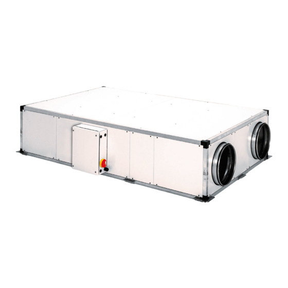
- Page 1 CADB/T-HE BASIC Heat recovery unit with integrated control...
-
Page 2: Table Of Contents
ENGLISH INDEX 1. INTRODUCTION ................................3 2. SAFETY REGULATIONS AND “CE” MARKING .......................3 3. GENERAL INSTRUCTIONS ............................3 4. UNIT LABELLING ................................3 5. HANDLING ...................................4 6. INSTALLATION ................................5 6.1. Introduction................................5 6.1.1. Outdoor installation ............................9 6.2. Dimensions and free space for maintenance ......................10 6.3. -
Page 3: Introduction
1. INTRODUCTION Thank you for purchasing this appliance. It has been manufactured in full compliance with applicable safety regulations and EU standards. Please read this instruction book carefully, as it contains important information for your safety during the installation, use and maintenance of this product. Keep it at hand for future reference. -
Page 4: Handling
5. HANDLING The CADB/T-HE models 04 to 33 are delivered fi xed with screws to the pallets. The models 45 to 100 are equipped with a bed, due to its weight are supplied without pallets. The unit can be handled by a pallet transporter, a forklift, or a crane. The handling machines will be adapted to the load and the lifting conditions. -
Page 5: Installation
6. INSTALLATION 6.1. INTRODUCTION Horizontal models size 04, 08, 12, 16, 21, 27 and 33 These models are designed to be installed hanging from the ceiling or located behind a false ceiling. When installing the unit, is mandatory to distribute the unit weight between all the supports existing in the units: •... - Page 6 Vertical models The models size 4 to 27 are supplied with support feets, while the models size 45 and 60 are supplied with a perimetral bed. This bed must be in contact with the ground or with a fl at surface. It is essential that the weight of the equipment was distributed between all points of support to prevent unit defor- mation.
- Page 7 SUPPLY FAN EXHAUST FAN Horizontal models size 45 and 60 are supplied with a perimetral bed. This bed must be in contact with the ground or with a fl at surface. It is essential that the weight of the equipment was distributed between all points of support to prevent unit deformation.
- Page 8 The drain is composed by 3 pieces: a) Drain pipe b) Female screw c) Joint ring. Install the two drains as indicated in the following drawing: a) Horizontal versions of CADB/T HE 04 to 33 b) Horizontal versions of CADT-HE 45 and 60 c) Vertical versions of CADB/T HE 04 to 33...
-
Page 9: Outdoor Installation
d) Vertical versions of CADT-HE 45 to 100 In these versions, the drainpipe and the siphon are supplied mounted in the unit. 6.1.1. Outdoor installation Whenever possible, it is advisable to be mounted indoors. When it is installed outdoors,it is prefe- rable to place the unit under a cover which offers enough protection to prevent rain falling directly to the unit, or install the corresponding rain canopy (TPP accessory). -
Page 10: Dimensions And Free Space For Maintenance
Both in the case that the Kit feet is used, or if the unit is based on antivibration pads, it is essential that the unit support was guaranteed on the 6 existing supporting points being all of them at a same plane. - Page 11 Distances for maintenance in installations with access from the bottom panels Conf. LH Access to fi lters and heat exchanger Access to fi lters and fan Access to control panel and fans Access to heat exchanger Conf. RH Distances for false ceiling installation Model Ø...
- Page 12 c) Vertical versions of CADB/T HE 04 to 33 Conf. LV (limpieza in situ) Access to fi lters and heat exchanger Access to control panel and fans Conf. RV Model Ø Weight (kg) 1125 1020 1275 1020 1325 1070 1475 1270 1750 1270...
-
Page 13: Mounting Process Of An Additional Supply Filter
6.3. MOUNTING PROCESS OF AN ADDITIONAL SUPPLY FILTER The heat recovery unit is supplied with the fi lters already installed. F7 (ePM1 70%) in supply side and M5 (ePM10 50%) in extract side. In addition, it is possible to mount a second fi lter in the unit (accessory). (For more information see section “Replacement of fi... -
Page 14: Electrical Connection
Condensation connection 6.5.3. Electrical connection In the recovery unit CADB/T-HE BASIC range, all components integrated into the device, are supplied into the electrical panel (motors, pressure fi lters, motor pressure switches, temperature sensors and by-pass damper). The electrical connection is limited to the connection of control terminal (10 m. of supplied cable) and possible electrical accessories as such as CO sensors and fi... -
Page 15: Configurations
6.6. CONFIGURATIONS CADB/T-HE BASIC standard confi guration From these confi gurations there are multiple variables that can be performed by the professional ins- taller quickly and easily. Panel replacement process The CADB-HE heat recovery units are available in two confi gurations LH and RH in the horizontal mo- dels and LV, RV in vertical models. -
Page 16: Control Functions
7. CONTROL FUNCTIONS MAIN ELEMENTS Control panel includes: General switch Electric box including control and wiring components, with access from side panel. FUNCTIONS Airfl ow adjustments Manual fans speed adjustment Automatic fans speed adjustment in VAV mode. Fans adjust their speed from the signal measured by an external sensor (CO , Relative humidity or Temperature) Automatic speed adjustment of the fans in COP mode (Constant Pressure). -
Page 17: Control Schemes
8. CONTROL SCHEMES Supply fan High-efficiency heat exchanger Extract fan Remote control panel Supply temperature probe Supply filter Outdoor temperature probe Extract filter Extract temperature probe Bypass actuator Exhaust temperature probe SCO2 CO2 sensor (accessory) FCD Polluted filters detector (pressure switch) Pressure sensor TDP-S (accessory. -
Page 18: Through Integration To Modbus Network (External Bms)
9.2.2. Through integration to Modbus network (external BMS) Integration into Modbus networks is incompatible with the use of the remote control. In addition to all- functionality available through the remote control, through the map of modbus registers it is possible to obtain the following functionalities and information: FUNCTIONALITY Automatic fan speed adjustment in COP (Constant Pressure) mode. -
Page 19: Free-Cooling Function Setting
The colour of the speed button lights up depending on the selected speed: Speed Default value* 0-10V signal Led colour 3,5 V Green MEDIUM Orange HIGH 9,5 V AUTO Flashing green * The set speeds are modifiable (See chapter Control settings). 9.3.2. -
Page 20: Setting The By-Pass Pass Temperature In Free-Cooling Mode
Operation in automatic mode The free-cooling / free-heating mode is programmed with the following algorithm: The lower tempera- ture limit of the T probe is a minimum of 12ºC, below this temperature the bypass operation does not happens in order to avoid discomfort due to the entry of air excessively cold. 9.3.3. -
Page 21: Modifi Cation Of Predefi Ned Speeds
Access to controller PCB selectors and jumpers Inside the electrical cabinet is the PCB controller, which has some selectors and jumpers through which it is possible to change the factory settings of the controller: Jumper Functionality Enable Modbus communication (Control of the unit from the BMS) In Modbus networks, defi... -
Page 22: Modifi Cation Of The Bypass Opening Setpoint (Free-Cooling Mode)
Selector position Selector 1 Selector 2 Selector 3 Selector 4 (Low speed) (Medium speed) (High speed) (Balance) (Vdc) (Vdc) (Vdc) -30 % -25 % -20 % -15 % -10 % -5 % 10 % 15 % 20 % 25 % 30 % Possible regulations depending on the position of the control selectors. -
Page 23: Fan Selection That Acts As A Master (Only Available On Units Controlled Via Modbus In Cop Mode)
9.4.3. Fan selection that acts as a master (only available on units controlled via Modbus in COP mode) Using the SW4.3 selector it is possible to defi ne which of the two fans acts as a master. The fan defi ned as master must be the one that supplies or extracts air from the network of ducts in which the pressure transmitter is installed. -
Page 24: Filter Supervision
9.4.5. Filter supervision CADB/T-HE BASIC heat recovery units are supplied with pressure switches mounted on both fi lters (supply and extraction). When the differential pressure value measured by the pressure switches exce- eds 200Pa an alarm is produced. Depending on the particularities of the installation (operating hours and polution of the outdoor environment) it may be advisable to change the pressure switch setting as indicated in the following table: Filters state... -
Page 25: Boost Function - Forced High Speed (Only Available In Models 04 To 27)
The position of jumper JP6 defi nes the type of supervision confi gured. This setting is made at the factory, so the installer should not change these settings. Heat recovery unit model Jumper JP6 Function CADB-HE-D 04 to 27 Closed-ON Supervision by control of fan RPM CADT-HE-D 33 to 100 Open-OFF... -
Page 26: Building Management System (Bms) Connection
10. BUILDING MANAGEMENT SYSTEM (BMS) CONNECTION Jumper Functionality Enable Modbus communication (Control of the unit from the BMS) In Modbus networks, defi ne the last unit of the network (End of line) The controller has a Modbus communication module through which it is possible to control the unit from an external BMS, as well as monitor a large part of the functional variables of the unit. - Page 27 Basic characteristics of the Modbus-RTU controller Addressing Slave: confi gurable address from 1 to 247 Diffusion Transmission speed 9600 Parity EVEN Mode Electrical interface RS-485 2W-wired or RS232 Connector type RJ 45 MODBUS message Address Function Data CRC verifi cation 8 bits 8 bits N x 8 bits...
- Page 28 Nº Type of register Description Range Data Default Comments Reg. value MODBUS confi guration Holding Register Communication 1 - 247 Channel / channel Node Holding Register Baudrate 1200 2400 4800 9600 14400 19200 28800 38400 56000 57600 115200 Holding Register Parity Without parity 2 Involves that will exist...
- Page 29 Nº Type of register Description Range Data Default Comments Reg. value Fans operation mode VAV Holding Register Selected speed Low speed Medium speed High speed Automatic Holding Register Low speed 0,5 - 5 Volts Holding Register Medium speed 3 - 8 Volts Holding Register High speed...
- Page 30 Nº Type of register Description Range Data Default Comments Reg. value Fans operation mode COP Holding Register Sensor range 0 - 2500 Pascal 2500 Holding Register Setpoint 0 - End of Pascal range Holding Register 1 - 250 Proportional constant Holding Register 1 - 250 Integral...
- Page 31 Nº Type of register Description Range Data Default Comments Reg. value Holding Register Not used Holding Register Tiempo de espera 1 - 40 Minutes post Open Bypass Holding Register Fan speed 0,1 - 2 V/min deceleration ramp Clogged fi lter alarm Discret input Alarm status Alarm not...
-
Page 32: Inspection, Maintenance And Cleaning
11. INSPECTION, MAINTENANCE AND CLEANING 11.1. REPLACEMENT OF FILTERS The Pro-Reg control incorporates a function of supervision of the fi lters clogging. When the fi lter replacement is required, the display shows an alarm message. The registers ubication for fi lters maintenance depends on the model and version. The exact ubication of the fi... -
Page 33: Filter Installation
Replacement fi lters are delivered in a plastic bag for extra protection. Remove the bag before installing the fi lter into the unit. Before installing the fi lter make sure that the airfl ow direction is correct. (indicated by an arrow in the fi... -
Page 34: Heat Exchanger
11.3. HEAT EXCHANGER Horizontal models CADB/T HE 04 to 33 To perform the heat exchanger cleaning it is necessary to remove it from the unit. The disassembly can be easily done from the lateral panel: Disassembly sequence Models 04 to 33: Access to heat exchanger cleaning from lateral panels and from the bottom panels. In order to have a good access to heat exchanger it is necessary to remove it form the heat recovey unit. -
Page 35: Condensation Drainpipe
Horizontal models CADB/T-HE 45 and 60 Due to the dimensions and weight of heat exchanger, the cleaning of it has to be perform in situ, without disassembly the heat exchanger. To access to the heat exchanger, disassembly the side panels of the heat recovery unit and proceed with the cleaning by blowing with compressed air. -
Page 36: Operation Anomalies
12. OPERATION ANOMALIES 12.1. GENERAL ANOMALIES Anomaly Cause Solution Diffi cult to start. Reduced power supply voltage. Check motor specifi cation plate. Insuffi cient static torque of Close the air inlets to reach the maximum motor. speed.Change the motor is necessary. Contact the S&P Post-Sales service. - Page 37 The number of LED fl ashes refers to the type of error detected: Priority Alarm/Status Actuation Communication error Red led, 1 blink Stop the unit between hand terminal and electronic board Extraction fan failure Red led, 2 blinks Stops unit after 90 s (adjustable) from the “Fan Fault”...
-
Page 38: Wiring Diagrams
13. WIRING DIAGRAMS 13.1. MODELS CADB-HE-D 04 TO 27 BASIC... -
Page 39: Models Cadb-He-D 33 To 100 Basic
13.2. MODELS CADB-HE-D 33 TO 100 BASIC... - Page 40 S&P SISTEMAS DE VENTILACIÓN, S.L.U. C. Llevant, 4 Polígono Industrial Llevant 08150 Parets del Vallès Barcelona - España Tel. +34 93 571 93 00 Fax +34 93 571 93 01 www.solerpalau.com Ref. 9023051700...
Need help?
Do you have a question about the CADB-HE BASIC Series and is the answer not in the manual?
Questions and answers