
Related Manuals for Honeywell HPM


Summary of Contents for Honeywell HPM
- Page 1 TotalPlant Solution (TPS) System High-Performance Process Manager Service HP13 R688 December 2020 Release R688...
- Page 2 In no event is Honeywell liable to anyone for any indirect, special or consequential damages. The information and specifications in this document are subject to change without notice.
- Page 3 About This Document This document provides instructions for servicing the High-Performance Process Manager (HPM). The instructions consist of fault isolation and removal/replacement procedures at the Optimum Replaceable Unit (ORU) parts level. ATTENTION With TPN R684, Enhanced Universal Control Network (EUCN) is introduced.
- Page 4 References References The following list identifies all documents that may be sources of reference for material discussed in this publication. Document Title HPM Specification and Technical Data HP03-600 HPM Planning HP02-600 HPM Installation HP20-600 HPM Checkout HP20-510 PM I/O Installation (PM/APM/HPM)
- Page 5 Support and Other Contacts Support and Other Contacts For support, contact your local Honeywell Process Solutions Customer Contact Center (CCC). To find your local CCC visit the website, https://www.honeywellprocess.com/en-US/contact-us/customer-support- contacts/Pages/default.aspx. R688 HPM High-Performance Process Manager Service December 2020 Honeywell...
- Page 6 Functional earth terminal: Used for non-safety purposes such as noise immunity improvement. NOTE: This connection shall be bonded to Protective Earth at the source of supply in accordance with national local electrical code requirements. HPM High-Performance Process Manager Service R688 Honeywell December 2020...
- Page 7 Chassis Ground: Identifies a connection to the chassis or frame of the equipment shall be bonded to Protective Earth at the source of supply in accordance with national and local electrical code requirements. R688 HPM High-Performance Process Manager Service December 2020 Honeywell...
- Page 8 Symbol Definitions viii HPM High-Performance Process Manager Service R688 Honeywell December 2020...
-
Page 9: Table Of Contents
Detailed Diagnostic display switch ........................40 Debug connector .............................. 40 HPMM +5 volt power margins .......................... 41 HPM UCN Interface module illustration ......................41 High-Performance Comm/Control card ......................42 High-Performance I/O Link card ........................43 EHPM Card Files ........................44 Introduction ............................... - Page 10 EIA interface limitations ............................ 66 Power Adapter installation..........................66 Power Adapter size ............................66 New SI IOP Slot Summary display to view Array points built on the SI FTA ............ 66 HPM High-Performance Process Manager Service R688 Honeywell December 2020...
- Page 11 48 volt battery backup time duration ......................... 89 CMOS backup time duration ..........................90 PSM redundancy requirements ........................90 Early production Standard Power System ......................91 HPM Standard Power System .......................... 92 AC Only Power System ............................ 93 2.16 Power Distribution ....................... 94 Overview ................................
- Page 12 Contents No battery backup (early production Standard Power System) ................ 95 No battery backup (HPM Standard Power System) ..................96 CMOS Battery Backup ............................. 96 Standard Power System (early production) ...................... 97 HPM Standard Power System .......................... 98 AC Only Power System ............................ 98 2.17...
- Page 13 Secondary HPMM determination ........................164 Two methods of pinning ..........................164 7-Slot card file pinning ............................ 165 15-Slot card file pinning ..........................166 Two pinning methods ............................. 166 Pinning method differences ..........................166 R688 HPM High-Performance Process Manager Service xiii December 2020 Honeywell...
- Page 14 Nonredundant HPMM subsystem ........................171 7-Slot card files .............................. 171 15-Slot card file redundant HPMM subsystem ....................172 7-Slot card file redundant HPM subsystem ....................172 IOP Only card file pinning location ......................... 173 Two pinning methods ............................. 173 One method only ............................173 Jumper method example ..........................
- Page 15 DETAIL STATUS Target ..........................211 System Error Journal Messages ........................211 HPM Status Displays......................211 Introduction ..............................211 HPM Status Displays ............................211 Primary and secondary HPMMs ........................212 HPMM node number ............................213 HPMM operational states ..........................213 Primary HPMM status ............................. 213 Secondary HPMM status ..........................
- Page 16 HPMM Write Lockout Control Display ......................243 Control Configuration display information ...................... 244 Schedule Overrun Counters ........................... 245 HPM Write Lockout Displays .......................... 245 HPMM Schedule Information Display ......................248 HPMM UCN Statistics Displays ........................249 HPMM Maintenance Support Displays ......................251 Manufacturing Information display .........................
- Page 17 Indicator functionality ............................355 High-Performance Comm/Control card Status indicator ................. 356 High-Performance I/O Link card Status indicator ................... 356 HPM UCN Interface module Transmit indicator ....................357 Power and Status indicators ........................... 357 HPMM fuse ..............................357 UCN Interface Module fuse ..........................357 HPMM Card extractors ...........................
- Page 18 Notification Displays ............................363 Cold HPMM Startup Display Sequences ......................363 HPMM Load display sequence ........................365 Nonredundant HPM Failure Sequences (After Load) ..................366 HPMM RAM Retention Startup Sequence ..................... 368 HPMM Redundancy Display Sequences ....................... 369 HPMM Alphanumeric Display Blanking ......................371 HPMM Diagnostic Tests List ..........................
- Page 19 HPMM and IOP Cards......................404 Removal and Replacement ..........................404 HPMM and IOP card removal and replacement ..................... 404 HPM UCN Interface module removal and replacement .................. 404 Tightening the knurled screw .......................... 405 HPM UCN Interface module ........................... 405 EHPM FTE module installation ........................
- Page 20 IOP or FTA substitution ..........................435 Equipment Required......................436 Precision equipment is a necessity ........................ 436 You will need precision equipment to accurately recalibrate these subsystems............436 Equipment requirements ..........................436 HPM High-Performance Process Manager Service R688 Honeywell December 2020...
- Page 21 HPMM swap verification ..........................460 IOP Redundancy ........................460 Introduction ..............................460 IOP redundancy terminology .......................... 460 IOP redundancy test procedure ........................460 Redundant 8-Channel Analog Output IOPs ................ 461 Introduction ..............................461 R688 HPM High-Performance Process Manager Service December 2020 Honeywell...
- Page 22 Periodic maintenance parts list ........................465 ORU parts List ..............................467 Conformally coated ORU parts list ......................... 483 UCN/EUCN Parts ........................493 UCN Parts list ..............................493 EUCN Parts list .............................. 495 xxii HPM High-Performance Process Manager Service R688 Honeywell December 2020...
- Page 23 Table 16 ENB Cable Faults ............................ 149 Table 17 EHPM Cable Faults ..........................151 Table 18 UCN Node (PM/APM/HPM) Cable Faults (Primary NIM node is an ENB) ..........152 Table 19 UCN Node (PM/APM/HPM) Cable Faults (Primary NIM node is a NIM) ..........153 Table 20 CF9 switch/uplink port failure ........................
- Page 24 Table 86 Galvanically Isolated HLAI Calibration Connector Pins ................445 Table 87 HPM Periodic Maintenance Parts ......................465 Table 88 Non-Conformally Coated HPM ORU Parts List ..................467 Table 89 Conformally Coated HPM ORU Parts List ....................483 Table 90 UCN Parts List ............................493...
- Page 25 Figure 32 HPM Standard Power System Backpanel ....................96 Figure 33 CMOS Battery Backup Assembly (Early Production) ................97 Figure 34 CMOS Battery Backup Assembly (HPM Standard Power System) ............98 Figure 35 Typical Cabinet 24 Vdc Power Distribution ....................99 Figure 36 Left 7-Slot HPMM Card File Backpanel 24 Vdc Distribution ..............
- Page 26 Figure 102 UCN Status Display – NIM Node and UCN CABLE STATUS Targets Selected ........201 Figure 103 UCN Status Display – HPM Node and UCN CABLE STATUS Targets Selected ........ 201 Figure 104 UCN Network Statistics Display ......................204 Figure 105 UCN Network Statistics Display –...
- Page 27 Figure 126 HPMM Write Lockout Control Display ....................243 Figure 127 HPM Write Lockout Target ........................245 Figure 128 HPM Write Lockout Control Display – Improper US Keylock Position ..........246 Figure 129 HPM Write Lockout Control Help Display ..................... 247 Figure 130 HPMM Schedule Information Display ....................
- Page 28 Figures Figure 179 IOP PI Loading Information Display ..................... 298 Figure 180 HPM Fault Isolation Flowchart (Sheet 1 of 6) ..................306 Figure 181 HPM Fault Isolation Flowchart (Sheet 2 of 6) ..................307 Figure 182 HPM Fault Isolation Flowchart (Sheet 3 of 6) ..................308 Figure 183 HPM Fault Isolation Flowchart (Sheet 4 of 6) ..................
-
Page 29: Introduction
Service philosophy The High-Performance Process Manager Service manual provides instructions for servicing the High- Performance Process Manager (HPM). The instructions consist of fault isolation and removal/replacement procedures at the Optimum Replaceable Unit (ORU) parts level. In addition, an ORU parts lists for current production hardware is provided. - Page 30 1 Introduction 1.2 Purpose of this Manual HPM High-Performance Process Manager Service R688 Honeywell December 2020...
-
Page 31: Equipment Description
24 Vdc power interrupt switch that is activated by unlocking and lifting the upper card extractor/insertion lever. Activating either HPMM card’s interrupt switch removes power from both HPMM cards and the HPM UCN Interface module in the card file, while activating an IOP card power R688... -
Page 32: Hpm Subsystem Overview
Right 7-Slot card file. All card slots accept IOPs. An older “IOP Only” card file may exist in a HPM cabinet that was upgraded to an HPM from a PM or APM. This older card file cannot support an HPMM card set. It is restricted to IOP cards and optional I/O Link Extender cards. -
Page 33: Card File Designations
HPMM card files. Nonredundant 7-Slot HPMM card file When configuring an HPM with a nonredundant HPMM by using a 7-Slot card file, the HPMM card set are typically installed in a Left 7-Slot card file. Redundant 7-Slot HPMM card files If an HPM is configured with redundant HPMMs using 7-Slot card files, HPMM card sets are installed in both a Left 7-Slot card file and in a Right 7-Slot card file. -
Page 34: Nonredundant Hpmm Cabinet Layout
Nonredundant HPMM cabinet layout The following figure is an illustration of an HPM cabinet that contains a nonredundant HPMM that is installed in left most card slots of the lower 15-Slot card file. IOPs are installed in the remaining slots of the lower card file and the 15-Slot card files above. -
Page 35: Hpmm And Iop Card Files
A High-Performance Process Manager (HPMM) card file is a 7-Slot or 15-Slot card file that is populated with an HPMM card set. The HPMM card set consists of following assemblies. High-Performance Comm/Control card High-Performance I/O Link card R688 HPM High-Performance Process Manager Service December 2020 Honeywell... -
Page 36: Hpmm Card File Configurations
HPM UCN Interface module The HPMM assemblies occupy the two left-most slot positions in the card file. The HPM UCN Interface module mounts in the connector beneath the High-Performance Comm/Control card in the first slot. HPMM card file configurations There are 3 HPMM card file configurations. -
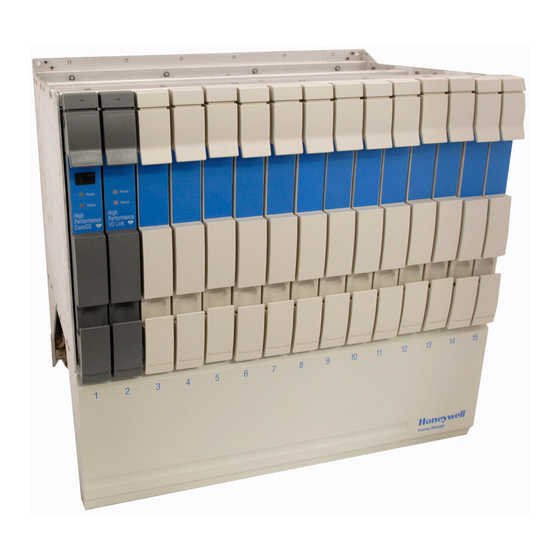
Page 37: 15-Slot Hpmm Card File
2 Equipment Description 2.5 HPMM Card Files 15-Slot HPMM card file The following figure is an illustration of a 15-Slot HPMM card file. Figure 2 15-Slot HPMM Card File R688 HPM High-Performance Process Manager Service December 2020 Honeywell... -
Page 38: Hpmm Functionality
Communications/Control card, an I/O Link driver/receiver interface, and a +24 Vdc to +5 Vdc power converter that provides +5 Vdc for both HPMM cards and the HPM UCN Interface module. HPM UCN Interface Module Consists of 5 Mbps IEEE 802.4 compatible... -
Page 39: Power Indicators
(not blinking) after the HPMM is loaded with the operating personality software, and enters the OK state. The UCN cables in use indicators are visible at the front of the HPM UCN Interface module (Rx-A and Rx-B) as well as under the front cover of the High-Performance Comm/Control card (UCN A and UCN The Transmit (Tx) indicator at the front of the HPM UCN Interface module is an indication of UCN cable transmit activity. -
Page 40: Diagnostic Display Analysis Example
Debug connector The High-Performance Comm/Control card has a debug connector (Debug) under the front cover. The connector is used by Honeywell engineering with specialized equipment and design level knowledge. The factory also uses the connector. HPM High-Performance Process Manager Service... -
Page 41: Hpmm +5 Volt Power Margins
Power margining is effective as soon as the jumper is moved. Honeywell does not recommend the use of power margins on any device that is on-process. Figure 5 High-Performance I/O Link Card (Front Panel) identifies the pinning selections on the High-Performance I/O Link card with a single jumper. -
Page 42: High-Performance Comm/Control Card
The following figure illustrates the front of the High-Performance Comm/Control card as well as the indicators, Diagnostic display, Detailed Diagnostic switch, and Debug connector that are located under the front cover. Figure 4 High-Performance Comm/Control Card (Front Panel) HPM High-Performance Process Manager Service R688 Honeywell December 2020... -
Page 43: High-Performance I/O Link Card
The following figure illustrates the front of the High-Performance I/O Link card as well as the voltage margin jumper pins that are located under the front cover. Figure 5 High-Performance I/O Link Card (Front Panel) R688 HPM High-Performance Process Manager Service December 2020 Honeywell... -
Page 44: Ehpm Card Files
EHPM card file configurations There are 3 EHPM card file configurations. They are as follows: Left 7-Slot EHPM card file Right 7-Slot EHPM card file 15-Slot EHPM card file HPM High-Performance Process Manager Service R688 Honeywell December 2020... -
Page 45: 15-Slot Ehpm Card File
2 Equipment Description 2.6 EHPM Card Files 15-Slot EHPM card file The following figure is an illustration of a 15-Slot EHPM card file. Figure 5.1 15-Slot EHPM Card File R688 HPM High-Performance Process Manager Service December 2020 Honeywell... -
Page 46: Ehpm Functionality
Communications/Control card an I/O Link driver/receiver interface a +24 Vdc to +5 Vdc power converter that provides +5 Vdc for both HPMM cards and the EHPM FTE Interface module. HPM High-Performance Process Manager Service R688 Honeywell December 2020... -
Page 47: Card/Module Illustrations
EHPM is in the Alive state, such as Axxx. In addition, for EUCN, the 4-digit diagnostic display includes the UCN Node Number, FTE Device Index and the R688 HPM High-Performance Process Manager Service December 2020 Honeywell... -
Page 48: Diagnostic Display Analysis Example
Debug connector The Enhanced High-Performance Comm/Control card has a debug connector (Debug) under the front cover. The connector is used by Honeywell engineering with specialized equipment and design level knowledge. HPM High-Performance Process Manager Service R688... -
Page 49: Ehpm +5 Volt Power Margins
Power margining is effective as soon as the jumper is moved. ATTENTION Honeywell does not recommend the use of power margins on any device that is on-process. Figure 5 High-Performance I/O Link Card (Front Panel) identifies the pinning selections on the High Performance I/O Link card with a single jumper. -
Page 50: Cf9 Ethernet Switch
The EHPM Comm/Control card has upgradable firmware. If the EUCN is connected to an Experion network, the firmware can be upgraded from the Experion system. If the EUCN is not connected to an HPM High-Performance Process Manager Service R688 Honeywell... -
Page 51: Ehpm Front Panel Led Display Information
EHPM either has a duplicate FTE Identify the duplicate problem in the Device Index, or duplicate PdTag, or FTE Community (using $FTESTS2 schematic or PC’s FTE Status both duplicate FTE Device Index and R688 HPM High-Performance Process Manager Service December 2020 Honeywell... -
Page 52: Service Failed Ehpm Cards Flashed With Experion-Integrated Firmware
High-Performance I/O Link card about 2 inches (but leave the I/O Link card in the card file chassis) from the HPM card file chassis. Remove the 3rd port redundancy cable (crossover cable attached to the orange port) between the redundant EHPMs. - Page 53 High-Performance I/O Link card about 2 inches (but leave the I/O Link card in the card file chassis) from the HPM card file chassis. Remove the FTE Interface card from the FILE_1 or LEFT chassis and change the index back to the original device index.
- Page 54 High-Performance I/O Link card about 2 inches (but leave the I/O Link card in the card file chassis) from the HPM card file chassis. Remove the newly flashed EHPM card, and place it back into its static-free bag. It is ready now for use in another EHPM chassis.
-
Page 55: Iop Card Files
The 15-Slot card file (HPMM or IOP type) cannot share its I/O Link Interface address with another card file. It is conceivable that sixteen 7-Slot card files can exist in a HPM subsystem (eight Left 7-Slot and eight Right 7-Slot card files). -
Page 56: 15-Slot Iop Card File
2 Equipment Description 2.8 IOP Card Files 15-Slot IOP card file The following figure illustrates a 15-slot IOP card file. Figure 6 15-Slot IOP Card File HPM High-Performance Process Manager Service R688 Honeywell December 2020... -
Page 57: Types Of Input/Output Processors (Iops)
FTA. Some models of the following types of IOPs support redundancy. Smart Transmitter Interface (STI) High Level Analog Input (HLAI) Digital Input (DI) Digital Output (DO) R688 HPM High-Performance Process Manager Service December 2020 Honeywell... -
Page 58: Redundant Hlai Iops
The following figure illustrates an HLAI FTA that interfaces with a pair of HLAI IOPs that are installed in separate 7-Slot card files. Figure 7HLAI FTA with Redundant HLAI IOPs Primary Secondary HPMM Card File HPMM Card File Field Wiring Terminals Redundancy Model HLAI FTA 32755 HPM High-Performance Process Manager Service R688 Honeywell December 2020... -
Page 59: Redundant Ao Iops
FTA. The following figure is an illustration of an Analog Output FTA interface with two Analog Output IOPs. Figure 8 Analog Output FTA with Redundant Analog Output IOPs Primary Secondary HPMM Card File HPMM Card File Field Wiring Terminals Redundancy Model Analog Output FTA 327 56 R688 HPM High-Performance Process Manager Service December 2020 Honeywell... -
Page 60: Low Level Multiplexer Iop (Llmux)
B-Size (mercury-wetted relays) at all tim es and ins tall ed in the cabinet or a NEMA 12 mounting box. LLMux Model s MU-TAMR02 (RTD) MU-TAMT02/12 (TC) FTAs 2910 HPM High-Performance Process Manager Service R688 Honeywell December 2020... -
Page 61: Field Termination Assemblies For Iop
16-input FTAs. The following figure illustrates the RHMUX IOP, Power Adapter, and Thermocouple FTA interconnections for a CE Compliant application. See the Process Manager I/O Installation manual for detailed information. R688 HPM High-Performance Process Manager Service December 2020 Honeywell... -
Page 62: Rhmux Thermocouple Fta
The Power Adapter provides power to the FTA(s) from the IOP. Both types of Power Adapters can be installed on an FTA Mounting Channel. The FTA’s dimensions (size) are non-standard and prevent installing the FTA on a standard FTA Mounting Channel. HPM High-Performance Process Manager Service R688 Honeywell... -
Page 63: Iop To Power Adapter Connection
The Serial Device Interface FTA has both EIA-232 (RS-232) and EIA-422/485 (RS-422/485) asynchronous serial communications interfaces, one of which is active, using either a DB-25 or a 5- terminal compression connector, respectively. R688 HPM High-Performance Process Manager Service December 2020 Honeywell... -
Page 64: Sdi Interface Configuration
Model Note: MU-MASX02 Manual/Auto Total maxim um length can be up to 1200 me ters Sta tion (40 00 feet) when using the appropriate type of ca ble. Device 4 5007 HPM High-Performance Process Manager Service R688 Honeywell December 2020... -
Page 65: Eia-232 And Eia--422/485 Interfaces
Model MU-TSDM02 FTA The model MU-TSDM02, assembly number 51303932-202, Serial Device Interface FTA accommodates up to four model MU-MASX02 Manual/Auto Station devices, manufactured by Honeywell Inc., through its EIA-422/485 (RS-422/485) interface. Model MU-TSDU02 FTA The model MU-TSDU02 Serial Device Interface FTA accommodates up to four model MU-MASX02 UDC 6000 devices, manufactured by Honeywell Inc., through its EIA-422/485 (RS-422/485) interface. -
Page 66: Serial Interface Iop (Si)
SLOT SELECT target has been removed as the slot numbers listed in this display are that of array points that can range from 1 – 511, spread across the new 2-page display. HPM High-Performance Process Manager Service R688 Honeywell... -
Page 67: Model Mu-Tsim12 Interconnections
See note . Mo dbus Note: Protocol Device Total maximum length can be up to 1200 meters (4000 fee t) whe n usin g the appropriate type of cable. Device 15 6582 R688 HPM High-Performance Process Manager Service December 2020 Honeywell... -
Page 68: Si Fta Installation
Model MU-TSIM22 EIA-422/485 interface The model MU-TSIM22 Serial Interface FTA, in combination with the model MU-PSIM11 IOP and the Power Adapter, provides an EIA-422/485 (RS-422/485) communications interface for peripherals that have an EIA-422/485 interface. HPM High-Performance Process Manager Service R688 Honeywell December 2020... -
Page 69: I/O Link Extender (Fiber Optic Link)
Figure 14 Standard I/O Link Extender Interconnections with Redundant HPMMs Figure 15 Long Distance I/O Link Extender Interconnections with Nonredundant HPMM Figure 19 Long Distance I/O Link Extender Interconnections with Redundant HPMMs R688 HPM High-Performance Process Manager Service December 2020 Honeywell... -
Page 70: Features And Guidelines
For the Long Distance I/O Link Extender, cycling power resets both ends of the link. The Standard I/O Link Extender must be manually reset at both ends of the link. The Long Distance I/O Link Extender can be reset by cycling power at one end of the link. HPM High-Performance Process Manager Service R688 Honeywell... -
Page 71: Standard I/O Link Extender Connections Nonredundant Hpmm
3. Remote Site #2's IOP card file is configured as card file #3 (I/O Link address of 2). 4. Remote Site #3's IOP card file is configured as card file #4 (I/O Link address of 3). 3277 7 R688 HPM High-Performance Process Manager Service December 2020 Honeywell... -
Page 72: Standard I/O Link Extender Connections Redundant Hpmms
4. Remote Site #2' s IOP card file is configured as card file #4 (I/O Link Address of 3). 5. Remote Site #3' s IOP card file is configured as card file #5 (I/O Link Address of 4). 327 78 HPM High-Performance Process Manager Service R688 Honeywell... -
Page 73: Long Distance I/O Link Extender Connections Nonredundant Hpmm
2. Remote Site #1's IOP card file is configured as card file #2 (I/O Link Address of 1). 3. Remote Site #2's IOP card file is configured as card file #3 (I/O Link Address of 2). 327 79 R688 HPM High-Performance Process Manager Service December 2020 Honeywell... -
Page 74: Long Distance I/O Link Extender Connections Redundant Hpmms
3. Remot e Site #1's IOP card file is configured as card file #3 (I/ O Link address of 2). 4. Remot e Site #2's IOP card file is configured as card file #4 (I/ O Link address of 3). 3278 0 HPM High-Performance Process Manager Service R688 Honeywell... -
Page 75: 2.13 Field Termination Assembly
High-level inputs such as voltage sources (0-5 V) and 4-20 milliamp current loop devices are acceptable.The inputs are isolated from each other and the HPM, but share a common bus for field wire shields. Low Level Analog Input... - Page 76 Digital Output (DO) HPM. 3-30 Vdc Solid-State Provides dc power digital outputs that are isolated from each other and the HPM. Digital Output (DO) 31-200 Vdc Solid-State Provides dc power digital outputs that are isolated from each other and the HPM.
-
Page 77: Galvanically Isolated Ftas
The 24 Vdc DO FTA provides isolated digital outputs to loads such as solenoid valves or lamps. Three physical sizes The standard FTAs have three physical sizes as illustrated in the following figure. The Galvanically Isolated FTAs are one size only, B-size. R688 HPM High-Performance Process Manager Service December 2020 Honeywell... -
Page 78: Fta Mounting Channels
Galvanically Isolated FTAs must not be mounted on the same FTA Mounting Channel. Mounting both types of FTAs on the same FTA Mounting Channel is an intrinsic safety violation because their field wiring will be routed together. HPM High-Performance Process Manager Service R688 Honeywell... -
Page 79: Vertical Orientation
Troubleshooting, opening this equipment and removing any panels or covers will expose the user to the risk of a shock hazard. There are no user serviceable parts inside this equipment. Refer all servicing only to qualified service personnel. R688 HPM High-Performance Process Manager Service December 2020 Honeywell... -
Page 80: Typical Cabinet Layout
A typical cabinet layout of FTA Mounting Channels that demonstrates the installation of standard FTAs in a dual access High-Performance Process Manager cabinet is shown in the following figure. Figure 18 Typical Vertical FTA Mounting Channel Layout HPM High-Performance Process Manager Service R688 Honeywell... -
Page 81: Compression Or Screw Terminals Available
The Marshalling Panel and Combiner Panel are available only with screw-type terminals. FTA compression-type terminal connector The following figure is an illustration of a typical compression-type terminal connector connection to a standard FTA. Figure 19 Typical FTA Compression Terminal Connector R688 HPM High-Performance Process Manager Service December 2020 Honeywell... -
Page 82: Fta Fixed Screw Terminal Connector
FTA. Figure 20 Typical FTA Fixed Screw Terminal Connector FTA removable screw-type connector The following figure illustrates a typical removable screw-type terminal connector. Figure 21 Typical FTA Removable Screw Terminal Connector HPM High-Performance Process Manager Service R688 Honeywell December 2020... -
Page 83: Galvanic Isolation Module Connectors
0.3 to 3.5 mm 2 (12 to 22 AWG) wiring. Crimp pin-type terminal connector The following figure illustrates the crimp pin-type Galvanic Isolation Module terminal connector. Figure 22 Crimp-Type Galvanic Isolation Module Terminal Connector R688 HPM High-Performance Process Manager Service December 2020 Honeywell... -
Page 84: Compression-Type Terminal Connector
The following figure illustrates the compression-type Galvanic Isolation Module terminal connector. Figure 23 Compression-Type Galvanic Isolation Module Terminal Connector Wire Size 12-22 AWG 8.0 mm + 0.5 Connector Part Number 51191738-100 11376 HPM High-Performance Process Manager Service R688 Honeywell December 2020... -
Page 85: 2.14 Fta Mounting Channels
Channel because the vertical orientation of the FTA Mounting Channel is reversed. For EUCN, if you want to install the CF9 switch in an HPM cabinet, the top 24 inch of FTA tray must be cleared. The top six inches is left empty and the carrier adapter assembly, which is used for mounting the CF9, occupies the remaining 18 inches. -
Page 86: Dual Access Cabinet Installation
There are no user serviceable parts inside this equipment. Refer all servicing only to qualified service personnel. Figure 24 Vertical FTA Mounting Channel Installation – Dual Access Cabinet HPM High-Performance Process Manager Service R688 Honeywell December 2020... -
Page 87: Figure 25 Vertical Fta Mounting Channel Installation - Cf9 Mounting
2 Equipment Description 2.14 FTA Mounting Channels Figure 25 Vertical FTA Mounting Channel Installation – CF9 Mounting R688 HPM High-Performance Process Manager Service December 2020 Honeywell... -
Page 88: Single Access Cabinet Installation
There are no user serviceable parts inside this equipment. Refer all servicing only to qualified service personnel. Figure 26 Vertical FTA Mounting Channel Installation – Single Access Cabinet HPM High-Performance Process Manager Service R688 Honeywell December 2020... -
Page 89: 2.15 Power Systems
48 volt battery backup time duration The 48 volt battery backup time duration for a redundant HPM cabinet containing redundant HPMMs and a total of 40 IOPs (40 nonredundant or 20 redundant pairs) is approximately 20 minutes for a fully charged battery. -
Page 90: Cmos Backup Time Duration
2.15 Power Systems CMOS backup time duration The following CMOS backup durations are defined for a HPM cabinet containing redundant HPMMs and a total of 40 IOPs (40 nonredundant or 20 redundant pairs). The time duration depends on which type of power system exists in the specific HPM cabinet. -
Page 91: Early Production Standard Power System
Power Supply Module and the CMOS Battery Backup. The Power Supply Module in the later production Power System adjusts automatically to the input ac voltage. Figure 27 Standard Power System R688 HPM High-Performance Process Manager Service December 2020 Honeywell... -
Page 92: Hpm Standard Power System
Figure 28 is a illustration of the enhanced HPM Standard Power System configuration that will be shipped with all new HPM cabinets in the near future. Initial HPM shipments will have an early production Standard Power System instead. The Power System’s connectors, terminal strips, battery and fuse holders are an integral part of the Power System backpanel. -
Page 93: Ac Only Power System
Status LED Alkaline Battery Backup f or CMOS Memory Primary DC Out put Status LED 6.3 V Phase Ref erence f or LLAI Cabinet Fan Assembly Power Connections Fan Fuses 7690 R688 HPM High-Performance Process Manager Service December 2020 Honeywell... -
Page 94: 2.16 Power Distribution
The connections are located on the lower left side of the backpanel, behind the left Power Supply Module, in the HPM Standard Power System. Primary and redundant terminals can be wired in parallel from a single power line source, or wired separately from two power line sources. -
Page 95: 48 Volt Battery Switch
Battery P ack CMOS Battery Backup Board Connector Connector Cabinet Fan Connector and Fuse J 15 J 16 Zero Ohm Resistor C1 5 Jumpers C1 0 Pow er Supply Module Connectors R688 HPM High-Performance Process Manager Service December 2020 Honeywell... -
Page 96: No Battery Backup (Hpm Standard Power System)
2 hours a load is applied to the batteries and the voltage level is again tested. The early production Standard Power System uses 3 “AA” size NiCad batteries which provide approximately 12 hours of backup. The enhanced Standard HPM Power System uses 3 “C” size NiCad batteries which provide approximately 45 hours of backup. -
Page 97: Standard Power System (Early Production)
See the following figure for an illustration of the CMOS Battery Backup Assembly. Figure 33 CMOS Battery Backup Assembly (Early Production) ASST. NO. 51303968 - 100 F1 - 1 AM P Note: F1 is a 0.5 A time-delay fuse. 2510 R688 HPM High-Performance Process Manager Service December 2020 Honeywell... -
Page 98: Hpm Standard Power System
The older version is not forward compatible. See the following figure for an illustration of the latest version of CMOS Battery Backup Assembly. Figure 34 CMOS Battery Backup Assembly (HPM Standard Power System) ASSY. NO. 5 130 9206 - 10 0... -
Page 99: 2.17 24 Vdc Power Distribution
Three card files and a Digital Input Power Distribution Assembly or Galvanic Isolation Power Distribution Assembly can be redundantly powered. The enhanced HPM Standard Power System provides twelve 6-pin connectors located on its backpanel. This allows a greater flexibility in providing power to card files and Power Distribution assemblies. -
Page 100: 2.18 Cabinet Fan Assembly
The line frequency phase reference signal in the AC Only Power System configuration is not dependent upon the presence of the left or right side Power Supply Modules, since a constant voltage is supplied by the AC/DC Distribution Assembly. HPM High-Performance Process Manager Service R688 Honeywell... -
Page 101: 2.20 24 Vdc Fuse Protection
You must replace the IOP card. Both HPMM cards, High-Performance Communications/Control and High-Performance I/O Link, and the HPM UCN Interface module are protected by a fast-action 3.2 A fuse that is located on the High-Performance I/O Link card. The fuse is field replaceable. ... -
Page 102: Fuse Insertion
2 Equipment Description 2.20 24 Vdc Fuse Protection Fuse insertion Use the following procedure to insert a fuse in an HPM backpanel. Step Action Hold the outer barrel of the fusepuller with the fingers of one hand and depress the the fusepuller’s end cap with the thumb. -
Page 103: Left 7-Slot Hpmm Card File 24 Vdc Distribution
Left 7-Slot HPMM card file 24 Vdc distribution The following figure illustrates the 24 Vdc power distribution on the Left 7-Slot HPMM card file backpanel. Figure 36 Left 7-Slot HPMM Card File Backpanel 24 Vdc Distribution R688 HPM High-Performance Process Manager Service December 2020 Honeywell... -
Page 104: Left 7-Slot Iop Card File 24 Vdc Distribution
A fast-action 2 A fuse that is located on the backpl a ne protects each IOP/nongalvanically isolated FTA combination. A fast-action 0.5 A fuse that is located on the IOP card protects the IOP card. 327 65 HPM High-Performance Process Manager Service R688 Honeywell December 2020... -
Page 105: Left 7-Slot Card File Backpanel Fuse Locations
The following figure illustrates the locations of the individual fuses on the Left 7-Slot card file backpanel. Figure 38 Left 7-Slot Card File Backpanel Fuse Locations Figure 39 Left 7-Slot Card File Backpanel Fuse Locations for EHPM R688 HPM High-Performance Process Manager Service December 2020 Honeywell... -
Page 106: Right 7-Slot Card File
Slot 13 IOP card and associated FTA 2 A fast-action Slot 14 IOP card and associated FTA 2 A fast-action Slot 15 IOP card and associated FTA 2 A fast-action HLAI Optical Coupler Module, U1 HPM High-Performance Process Manager Service R688 Honeywell December 2020... -
Page 107: Right 7-Slot Hpmm Card File 24 Vdc Distribution
Right 7-Slot HPMM card file 24 Vdc distribution The following figure illustrates the 24 Vdc power distribution on the Right 7-Slot HPMM card file backpanel. Figure 40 Right 7-Slot HPMM Card File Backpanel 24 Vdc Distribution R688 HPM High-Performance Process Manager Service December 2020 Honeywell... -
Page 108: Right 7-Slot Iop Card File 24 Vdc Distribution
Right 7-Slot IOP card file 24 Vdc distribution The following figure illustrates the 24 Vdc power distribution on the Right 7-Slot IOP card file backpanel. Figure 41 Right 7-Slot IOP Card File Backpanel 24 Vdc Distribution HPM High-Performance Process Manager Service R688 Honeywell December 2020... -
Page 109: Right 7-Slot Card File Backpanel Fuse Locations
The following figure illustrates the locations of the individual fuses on the Right 7-Slot card file backpanel. Figure 42 Right 7-Slot Card File Backpanel Fuse Locations Figure 43 Right 7-Slot Card File Backpanel Fuse Locations for EHPM R688 HPM High-Performance Process Manager Service December 2020 Honeywell... -
Page 110: 15-Slot Card File
Slot 13 IOP card and associated FTA 2 A fast-action Slot 14 IOP card and associated FTA 2 A fast-action Slot 15 IOP card and associated FTA 2 A fast-action LLAI Optical Coupler Module, U1 HPM High-Performance Process Manager Service R688 Honeywell December 2020... -
Page 111: 15-Slot Hpmm Card File 24 Vdc Distribution
15-Slot HPMM card file 24 Vdc distribution The following figure illustrates the 24 Vdc power distribution on the 15-Slot HPMM card file backpanel. Figure 44 15-Slot HPMM Card File Backpanel 24 Vdc Distribution R688 HPM High-Performance Process Manager Service December 2020 Honeywell... -
Page 112: 15-Slot Iop Card File 24 Vdc Distribution
A fast-action 2 A fuse that is located on the backplane protects each IOP/nongalvanically isolated FTA combination. A fast-action 0.5 A fuse that is located on the IOP card protects the IOP card. 3 27 71 HPM High-Performance Process Manager Service R688 Honeywell December 2020... -
Page 113: 15-Slot Card File Backpanel Fuse Locations
The following figure illustrates a portion of the locations of the individual fuses on the 15-Slot card file backpanel. Figure 46 15-Slot Card File Backpanel Fuse Locations Figure 47 15-Slot Card File Backpanel Fuse Locations R688 HPM High-Performance Process Manager Service December 2020 Honeywell... -
Page 114: Iop Only Card File
The “IOP Only” card file assembly that is used by the Process Manager and Advanced Process Manager can be used with the High-Performance Process Manager. When upgrading a PM or APM to HPM hardware, it is not necessary to also convert the IOP card file(s) to 15-Slot IOP card file(s). -
Page 115: Iop Only Card File Fuse Protection
2 A fast-action/3 A time-delay Slot 14 IOP card and associated FTA 2 A fast-action/3 A time-delay Slot 15 IOP card and associated FTA 0.5 A fast-action LLAI Optical Coupler Module, U1 R688 HPM High-Performance Process Manager Service December 2020 Honeywell... -
Page 116: Iop Only Card File 24 Vdc Power Distribution
A fast-action 0.5 A fuse that is located in the card protects each IOP card. 5067 IOP Only card file backpanel fuse locations The following figure illustrates the locations of the individual fuses on the IOP Only card file backpanel. HPM High-Performance Process Manager Service R688 Honeywell December 2020... -
Page 117: Fta Fuse Protection
Some individual FTAs may have fuse protection on the assembly. In general, output type FTAs are fused, but not exclusively. Fuse information for the individual FTAs can be found in the Process Manager I/O Installation manual. R688 HPM High-Performance Process Manager Service December 2020 Honeywell... -
Page 118: Cabinet Fan Assembly Fuse Protection
The High-Performance I/O Link card provides the 5 Vdc operating power for the High-Performance Comm/Control and the HPM UCN Interface module by converting the unfused 24 Vdc from the backpanel. The 5 Vdc power is protected at the input to the converter by a 3.2 A surface-mounted fuse on the High-Performance I/O Link card. -
Page 119: Hpmm Power Routing And Fuses
HPMM power routing and fuses The HPMM components consist of the High-Performance Comm/Control card, High-Performance I/O Link card, and the HPM UCN Interface module. Figure 50 illustrates the power routing and fusing as it applies to the HPMM components. Note the location of the of the two fuses involved ... -
Page 120: 2.22 Card File Power Cabling
Standard Power System as shown in Figure 27. The AC Only Power System power connectors are located at the right side of its AC/DC Distribution assembly as shown in Figure 29. The HPM Standard Power System has 12 power output connectors as shown in Figure 28. Power distribution examples Figure 46, Figure 48, Figure 49, and Figure 50 illustrate typical power cabling of various combinations of card files and Power Distribution assemblies using the Standard Power System. -
Page 121: 15-Slot Card File With Power Distribution Assemblies
Figure 51 15-Slot Card File with Power Distribution Assemblies Card File 1 Digital Input Power Dis tribution Ass embly Power Sys tem Galvanic Is olation Power Dis tribution Ass embly 32 773 R688 HPM High-Performance Process Manager Service December 2020 Honeywell... -
Page 122: Two 15-Slot Card Files With Power Distribution Assemblies
15-Slot card files and two Power Distribution assemblies. Figure 52 Two 15-Slot Card Files with Power Distribution Assemblies Card File 2 Card File 1 Digital Input Power Distribution Assembly Power System Galvanic Isolation Power Distribution Assembly 327 74 HPM High-Performance Process Manager Service R688 Honeywell December 2020... -
Page 123: Three 15-Slot Card Files
The following figure is an illustration of power cabling for a typical High-Performance Process Manager configuration of three 15-Slot card files. Figure 53 Three 15-Slot Card Files Card File 3 Card File 2 Card File 1 Power S ystem 327 75 R688 HPM High-Performance Process Manager Service December 2020 Honeywell... -
Page 124: Three 15-Slot Card Files With Power Distribution Assemblies
Early production Standard Power Systems and AC Only Power Systems are limited to eight power output connectors. The following figure illustrates how power is distributed when the number of available connectors does not meet the total need for redundant cabling. HPM High-Performance Process Manager Service R688 Honeywell... -
Page 125: 2.23 I/O Link Interface Cabling
I/O Link Interface cable installations. The following table identifies the I/O Link Interface connectors on the 7-Slot, 15-Slot, and IOP Only card file backpanels. Table 10 I/O Link Interface Cabling Card File Connector Assignments R688 HPM High-Performance Process Manager Service December 2020 Honeywell... -
Page 126: Cable Length
The High-Performance Process Manager accommodates four types of card files. Use caution CAUTION when connecting the I/O Link Interface cables because of the differences between the card files. All card files have two I/O Link Interface receptacles marked LINKA and LINKB. HPM High-Performance Process Manager Service R688 Honeywell December 2020... -
Page 127: I/O Link Interface Cabling - Three Card Files
The following figure is an illustration of the I/O Link Interface cabling for an High-Performance Process Manager configuration that consists of two 7-Slot HPMM card files and one 15-Slot IOP card file. Figure 56 Three Card Files R688 HPM High-Performance Process Manager Service December 2020 Honeywell... -
Page 128: I/O Link Interface - Four Card Files
The following figure is an illustration of the I/O Link Interface cabling for an High-Performance Process Manager configuration that consists of two 7-Slot HPMM card files and two 15-Slot IOP card files. Figure 57 Four Card Files HPM High-Performance Process Manager Service R688 Honeywell... -
Page 129: I/O Link Interface Cables In Adjacent Cabinets
An induced power surge of 10 amperes or greater can originate through an FTA’s field connections as a result of a lighting strike and elevate the card file(s) above the common mode range of the HPM’s I/O Link Interface transceivers and cause transceiver failure. -
Page 130: New And Upgraded Subsystems Only
However, older hardware can and should be upgraded by the use of a set of power cable I/O Link protector adapters, Honeywell part number 51204127-100. Figure 58 Surge Protection Network Power Cables illustrates a set of the cables, cable A and cable B. -
Page 131: Surge Protection Network Power Cables
Figure 58 Surge Protection Network Power Cables LNK A LNK B LNK A LNK B 16506 I/O Link cable connection The following figure illustrates the I/O Link cable connection to the power cable’s surge protection network connector. R688 HPM High-Performance Process Manager Service December 2020 Honeywell... -
Page 132: Typical I/O Link And Power Cable Connection
The following figure illustrates typical surge protection network power cable and I/O Link Interface cable connections to the Power System and card files in a cabinet. Figure 60 Typical Cabinet Surge Protection Network Cable Connections HPM High-Performance Process Manager Service R688 Honeywell... - Page 133 2 Equipment Description 2.23 I/O Link Interface Cabling R688 HPM High-Performance Process Manager Service December 2020 Honeywell...
-
Page 134: Power Cable I/O Link Protector Adapters
Link A Link B LNK A LNK B I/ O Link A I/ O Link B Cable Cable Connect ion Connect ion Power Cable Power Cable Connect ion Connect ion 16604 HPM High-Performance Process Manager Service R688 Honeywell December 2020... -
Page 135: 2.24 Iop To Fta Cabling
IOP. Shielded FTA cables must be used whenever the FTA is located outside of the HPMM cabinet complex. See the High-Performance Process Manager Installation manual for additional information. R688 HPM High-Performance Process Manager Service December 2020 Honeywell... -
Page 136: Typical Cable Routing
2.24 IOP to FTA Cabling Typical cable routing The following figure for an illustration of typical cable routing for a standard FTA in a cabinet or cabinet complex. Figure 62 IOP to FTA Cabinet Cabling HPM High-Performance Process Manager Service R688 Honeywell December 2020... -
Page 137: 2.25 Power Adapter Cabling
NEM A 12 m ounting box. LLM ux Mo dels M U-T AM R02 (RT D) M U-T AM T 02/1 2 (T C) FT As 2910 R688 HPM High-Performance Process Manager Service December 2020 Honeywell... -
Page 138: Sdi Interconnections
Total maximum length can be up to 1.2 km (4000 f t) Station w hen using the appropriate type of cabl e . Device 4 5007 SI interconnections The following figure illustrates the Power Adapter interconnections for a Serial Interface application. HPM High-Performance Process Manager Service R688 Honeywell December 2020... -
Page 139: 2.26 Ucn Cable System
Manager Modules (HPMMs) and the Network Interface Module (NIM) on the LCN as illustrated in the following figure. Use of the two-drop UCN cable tap is illustrated. Figure 66 Universal Control Network (UCN) Components R688 HPM High-Performance Process Manager Service December 2020 Honeywell... -
Page 140: Redundant Ucn Cables
Cable A and Cable B. Redundant HPMMs should have their A cables connected to the same A tap, and their B cables connected to the same B tap. HPM High-Performance Process Manager Service R688 Honeywell... -
Page 141: Cable Tap Types
High-Performance Process Managers (four HPMMs), or multiple nonredundant HPMs at a location. The eight-drop cable tap supports up to four redundant (eight HPMMs) or eight nonredundant High-Performance Process Managers at a location. R688 HPM High-Performance Process Manager Service December 2020 Honeywell... -
Page 142: Isolated Port Identification
Card file backpanel connections The following figure illustrates the A and B UCN drop cable connections to the HPM UCN Interface module in a 7-Slot HPMM card file. -
Page 143: Figure 69 Enhanced Universal Control Network (Eucn) Components
2 Equipment Description 2.27 EUCN Cable System Figure 69 Enhanced Universal Control Network (EUCN) Components R688 HPM High-Performance Process Manager Service December 2020 Honeywell... -
Page 144: Redundant Eucn Fte Cables
(all other EUCN nodes) If FTE cable A on an ENIM has a problem If FTE cable B on an ENIM has a problem Single ENIM: If both FTE cable A and HPM High-Performance Process Manager Service R688 Honeywell December 2020... - Page 145 Note: The RESET STATS target can still be used to remove the indication of disjoined nodes. LCN system alarm can also be caused by a switch uplink failure (for example, CF9), check your upper-level network topology to confirm this. R688 HPM High-Performance Process Manager Service December 2020 Honeywell...
-
Page 146: Table 13 Crossover Cable Faults
Top Level Cross cable between the Yellow and Green Switches is disconnected If the FTE cable A and B on an EHPM are connected to the correct switch. HPM High-Performance Process Manager Service R688 Honeywell December 2020... -
Page 147: Cable Troubleshooting Guidelines For Eucn
FTE network and are connected by a crossover Ethernet cable. An ES-T is connected to L2 and is displaying an FTE Status display on the Native Window. The Native Window displays the status of the UCN as viewed by the ENIM/ENB pair. R688 HPM High-Performance Process Manager Service December 2020 Honeywell... -
Page 148: Table 15 Enb Network Topology Terminology
Redundant LCN Coax cables (the blue line indicates both A & B cable and the pair is not shown) FTE Crossover Cable An Ethernet crossover cable connected between the top level Yellow and Green Switches. HPM High-Performance Process Manager Service R688 Honeywell December 2020... -
Page 149: Table 16 Enb Cable Faults
FAIL/OK If both FTE cable A and FTE cable UCN: B on a secondary OK/BACKUP ENB have a LCN: OK/SEVERE problem FTE composite status A->A A->A A->A B->B R688 HPM High-Performance Process Manager Service December 2020 Honeywell... - Page 150 Note: If any SIL or NSY bits are set, then the corresponding cables are backlit on the UCN Status Display, if the UCN CABLE STATUS target is chosen. HPM High-Performance Process Manager Service R688 Honeywell...
-
Page 151: Table 17 Ehpm Cable Faults
Note: If any SIL or NSY bits are set, then the corresponding cables are backlit on the UCN Status Display, if the UCN CABLE STATUS target is chosen. R688 HPM High-Performance Process Manager Service December 2020 Honeywell... -
Page 152: Table 18 Ucn Node (Pm/Apm/Hpm) Cable Faults (Primary Nim Node Is An Enb)
2 Equipment Description 2.27 EUCN Cable System Table 18 UCN Node (PM/APM/HPM) Cable Faults (Primary NIM node is an ENB) Error scenario UCN COMM STATUS UCN CABLE $FTESTS2 $FTESTS2 STATUS/FTE displays displays CABLE STATUS (PM/APM/HPM (all other with cable faults) -
Page 153: Table 19 Ucn Node (Pm/Apm/Hpm) Cable Faults (Primary Nim Node Is A Nim)
Secondary takes over as primary Note: PM/APM/HPM are UCN nodes and hence the $FTESTS displays are not applicable. The FTE CABLE STATUS field is not available for NIMs. Note: The A SIL, B SIL, A NSY, and B NSY indications only appear for an instant and then shows blank due to node failure. -
Page 154: Table 20 Cf9 Switch/Uplink Port Failure
L2 node UCN: N/A connected to a LCN: OK/BACKUP FTE L2 Switch has a problem FTE composite status (for example, ES- T FTE Cable A A->A A->B B->A B->B fault) HPM High-Performance Process Manager Service R688 Honeywell December 2020... -
Page 155: Diagnosing Complex Eucn Fte Network Faults
Once multiple views are available compare the views and identify the common faults in the views. R688 HPM High-Performance Process Manager Service December 2020 Honeywell... -
Page 156: Figure 71 $Ftests2 View - Est05 Has Cable A Fault
EHPM although view and advanced control via the ENIM/ENB will be broken. Because the ENIM/ENB has a view to the secondary EHPM, the ENIM/ENB will retain FULL control and when one of the faults is corrected, view and advanced control will resume. HPM High-Performance Process Manager Service R688 Honeywell... -
Page 157: Figure 73 Ucn Status For L1 Switch A Down And Cf9 B Downlink Fault
Figure 73 UCN Status for L1 Switch A down and CF9 B downlink fault Figure 74 $FTESTS for L1 Switch A down and CF9 B downlink fault Primary ENIM/ENB Primary EHPM Secondary ENIM/ENB Secondary EHPM R688 HPM High-Performance Process Manager Service December 2020 Honeywell... -
Page 158: Eucn Switches
2.27 EUCN Cable System EUCN Switches EUCN FTE network security is achieved with the use of Level 1 Honeywell CF9 and Level 2 Industrial Ethernet switch (Cisco IE 3000) configurations. In larger EUCN topologies, you must configure the industrial Ethernet switch as a Level 1 and Level 2 switch, known as split switch configuration. -
Page 159: Status Indicators On The Fte Switch
Interpretation of Cisco IE 3000 Front Panel & Port LED Indicators You can use the LEDs to monitor the switch status, activity, and performance. The figure below shows the front panel LEDs, and the following sections describe them. R688 HPM High-Performance Process Manager Service December 2020 Honeywell... - Page 160 Flashing green interspersed with flashing amber A problem exists with this port to target device OR solid amber interface.Check the port configuration and cable integrity. If OK and condition still persists, contact HPM High-Performance Process Manager Service R688 Honeywell December 2020...
- Page 161 Pwr B LED: Applies only if redundant power sources are connected LED Color Description Solid green The switch is properly powered up. Red or amber The switch is not powered up.Contact the Honeywell Technical Assistance Center. R688 HPM High-Performance Process Manager Service December 2020 Honeywell...
-
Page 162: Control Firewall Status Indicators
Blinking Green with green brief flicker Power No Power Power On Status No Power of Normal Running *See Note Fault Operation POST Downlink No Power or Link Present, Link Too Many HPM High-Performance Process Manager Service R688 Honeywell December 2020... - Page 163 Note: The CF9 has detected a soft failure and is working in a diminished state. Typical causes are a disconnected uplink port cable or a downlink port with too many attached devices. (Only one device can be attached to a CF9 downlink port.) R688 HPM High-Performance Process Manager Service December 2020 Honeywell...
-
Page 164: 2.28 Ucn Node Address Pinning
System Console intervention. Two methods of pinning Two methods of UCN node address pinning are described later in this section. The HPM files normally use jumpers to define (pin) the UCN node address. Zero-ohm resistors (used in place of jumpers) are soldered in at the factory only by special request. -
Page 165: 7-Slot Card File Pinning
The following figure illustrates the location on a Left 7-Slot card file backpanel where the odd UCN node address must be configured (pinned). The location on Right 7-Slot card file backpanel is identical. Figure 78 Left 7-Slot Card File UCN Node Address Pinning R688 HPM High-Performance Process Manager Service December 2020 Honeywell... -
Page 166: 15-Slot Card File Pinning
Plug jumpers are convenient to set up and change. Zero-ohm resistor jumpers are reliable and permanent. One method or the other must be disabled at initial installation before the system will function properly. HPM High-Performance Process Manager Service R688 Honeywell... -
Page 167: Odd Number Of Jumpers Required
(if they exist). As an example, to configure a HPM for a UCN node address of 11, install jumpers at positions 1, 2, and 8 (1 + 2 + 8 = 11) by bridging the two circuit pins at each position. -
Page 168: Zero-Ohm Jumper Method
Because an odd number of resistors are required, the P (parity) jumper must be removed along with those at positions 4, 16, and 32. Use a diagonal cutter to clip out the unwanted resistors. Figure 81 UCN Node Address Pinning Using Zero-Ohm Resistors HPM High-Performance Process Manager Service R688 Honeywell... -
Page 169: Fte Device Index Addressing
PDTag which includes the UCN Address, the IP Address in use, and the FTE Device Index. This provides all of the information required for address resolution for EUCN connections. Figure 82 - EHPM FTE Interface Module R688 HPM High-Performance Process Manager Service December 2020 Honeywell... -
Page 170: 2.29 I/O Link Interface Address Pinning
Manager’s card file configuration. Two methods of pinning Two methods of I/O Link Interface address pinning are described later in this subsection. The HPM files normally use jumpers to define (pin) the card file address. Zero-ohm resistors that are used in place of jumpers are soldered in at the factory only by special request. -
Page 171: Nonredundant Hpmm Subsystem
Nonredundant HPMM subsystem For a HPM subsystem with a nonredundant HPMM and supporting I/O card files, the card file that contains the HPMM must be pinned for an I/O Link Interface address of zero (0), and the I/O card files that contain IOPs must be pinned for consecutive addresses that start at one (1). -
Page 172: 15-Slot Card File Redundant Hpmm Subsystem
I/O Link Interface address zero (0) and the second card file must be configured for I/O Link Interface address one (1). Any additional I/O card files in the HPM subsystem must be addressed consecutively, starting at I/O Link Interface address two (2). See the following figure for the location of the jumpers on the 15-Slot card file. -
Page 173: Iop Only Card File Pinning Location
Interface address is configured. The IOP Only card file may be part of the residual hardware from the upgrade of a PM or APM subsystem to an HPM subsystem. Figure 85 IOP Only Card File I/O Link Interface Address Pinning... -
Page 174: Jumper Method Example
Even though the J-number (J26 in this case) differs between the 7-Slot and 15-Slot card files, the method of pinning the card file address remains the same. Figure 86 Left 7-Slot Card File I/O Link Interface Address Pinning with Plug Jumpers HPM High-Performance Process Manager Service R688 Honeywell... -
Page 175: Zero-Ohm Resistor Jumper Pinning Example
CAUTION problem by resoldering the jumper. The backpanel is easily damaged. Instead, remove all the zero-ohm resistor jumpers and configure the card file’s I/O Link Interface address with the plug jumpers. R688 HPM High-Performance Process Manager Service December 2020 Honeywell... -
Page 176: 2.30 Firmware/Hardware/Software Correlation
A definite correlation exists between the High-Performance Process Manager’s firmware, hardware, and software. An explanation of this relationship and the latest information can be found in Appendix K of the Customer Release Guide manual. HPM High-Performance Process Manager Service R688 Honeywell... - Page 177 2 Equipment Description 2.30 Firmware/Hardware/Software Correlation R688 HPM High-Performance Process Manager Service December 2020 Honeywell...
-
Page 179: Ucn Status Displays
UCN Driver configuration and the NIM local UCN statistics. The NIM Local UCN Statistics display has a target that allows the operator to reset the UCN Driver statistics for test purposes. R688 HPM High-Performance Process Manager Service December 2020 Honeywell... -
Page 180: Hpmm Detail Status Displays
Use the following procedure to select a NIM Detail Status display. Step Action Depress the <SYST STAT> (System Status) key on the console to invoke the System Status display. The System Status display is shown in Figure 88. HPM High-Performance Process Manager Service R688 Honeywell December 2020... -
Page 181: System Status Display
UCN Status display to invoke the NIM Detail Status display. The NIM Detail Status display is shown in Figure 91. System Status display Figure 88 System Status Display R688 HPM High-Performance Process Manager Service December 2020 Honeywell... -
Page 182: Ucn Status Display
3 UCN Status Displays 3.3 Detail Status Display Selection Procedures UCN Status display Figure 89 UCN Status Display Figure 90 UCN Status Display – EHPM/ENIM HPM High-Performance Process Manager Service R688 Honeywell December 2020... - Page 183 UCN Cable status – when the UCN Cable Status target is selected. EUCN Node Type – when no target is selected or when the Load/Save Restore or Run States target is selected. R688 HPM High-Performance Process Manager Service December 2020 Honeywell...
-
Page 184: Nim Detail Status Display
3 UCN Status Displays 3.3 Detail Status Display Selection Procedures NIM Detail Status display Figure 91 NIM Detail Status Display HPM High-Performance Process Manager Service R688 Honeywell December 2020... -
Page 185: Hpmm Detail Status Display Procedure
The UCN Status display is shown in Figure 89. Choose the HPM of interest on the display grid and then select the DETAIL STATUS target on the UCN Status display to invoke the HPM Status display. The HPM Status display is shown in Figure 92. -
Page 186: Figure 93 Hpm Status Display - Ehpm
3 UCN Status Displays 3.3 Detail Status Display Selection Procedures Figure 93 HPM Status Display – EHPM HPM High-Performance Process Manager Service R688 Honeywell December 2020... -
Page 187: Primary Hpmm Detail Status Display
3 UCN Status Displays 3.3 Detail Status Display Selection Procedures Primary HPMM Detail Status display Figure 94 Primary HPMM Detail Status Display R688 HPM High-Performance Process Manager Service December 2020 Honeywell... -
Page 188: Secondary Hpmm Detail Status Display
3 UCN Status Displays 3.3 Detail Status Display Selection Procedures Secondary HPMM Detail Status display Figure 95 Secondary HPMM Detail Status Display HPM High-Performance Process Manager Service R688 Honeywell December 2020... -
Page 189: Iop Detail Status Display Procedure
The UCN Status display is shown in Figure 89. Choose the HPM that is associated with the IOP of interest on the display grid and then select the DETAIL STATUS target on the UCN Status display to invoke the HPM Status display. -
Page 190: Display Operation
<SYST STATS> (System Status) key on the console and then selecting the PROCESS NETWORK STATUS target on the display for the network you wish to examine. Figure 97 UCN Status Display HPM High-Performance Process Manager Service R688 Honeywell December 2020... -
Page 191: Three Display Sections
The “status boxes” in the middle grid-like section of the display provide the status of the configured UCN node. Type of device The type of device on the UCN is identified at the upper center of the status box, such as HPM, APM, PM, LM, or NIM. Primary or secondary When redundant, the numerals in the left and right upper corners identify the primary and secondary (if present) node addresses of the device, respectively. -
Page 192: Auxillary Status
(Text color – yellow) LOADING The HPM is being loaded with its personality program (Text color – yellow) and database. There is no UCN node configured for the HPM’s UCN NOTCONFG (Text color – yellow) node address. POWERON The HPM is responding to the UCN but has not (Text color –... -
Page 193: Secondary Hpmm Status
3.4 Display Operation Term Definition OFFNET The HPM is not responding on the UCN because 1) it (Text color – red) does not exist, 2) power is off, or 3) there is a hardware failure that prohibits a response. PARTFAIL There are one or more Partial failures. -
Page 194: Load/Save Restore Target
The LOAD/SAVE RESTORE target functions are not applicable when a NIM is chosen on the UCN Status display. Command targets The command targets at the bottom of the display in Figure 98 perform the functions defined in Table 26 UCN Status Display – LOAD/SAVE RESTORE. HPM High-Performance Process Manager Service R688 Honeywell December 2020... -
Page 195: Table 26 Ucn Status Display - Load/Save Restore
Clears the LOAD PROGRAM, RESTORE DATA, SAVE DATA, LADDER LOAD, LADDER SAVE, and ENTER command targets from the display. ENTER The ENTER target must be selected for the chosen LOAD/SAVE RESTORE function to be executed. R688 HPM High-Performance Process Manager Service December 2020 Honeywell... -
Page 196: Control States Target
Figure 99 UCN Status Display – CONTROL STATES Target Selected Not applicable for NIM The CONTROL STATES target functions are not applicable when a NIM is chosen on the UCN Status display. HPM High-Performance Process Manager Service R688 Honeywell December 2020... -
Page 197: Table 27 Ucn Status Display - Control States Target Selected
Changes the UCN’s control state to BASIC. The command UCN BASIC CONTROL is executed by selecting the ENTER target. Changes the HPM’s control state to FULL. The command DEV FULL CONTROL is executed by selecting the ENTER target. Changes the HPM’s control state to BASIC. The command DEV BASIC CONTROL is executed by selecting the ENTER target. -
Page 198: Auto Checkpt Target
Figure 100 UCN Status Display – AUTO CHECKPT Target Selected Not applicable for NIM The AUTO CHECKPT target functions are not applicable when a NIM is chosen on the UCN Status display. HPM High-Performance Process Manager Service R688 Honeywell December 2020... -
Page 199: Table 28 Ucn Status Display - Auto Checkpt Target Selected
Clears the UCN CKPT ENABLE, UCN CKPT INHIBIT, DEV CKPT ENABLE, DEV CKPT INHIBIT, and ENTER command targets. ENTER The ENTER target must be selected for the chosen AUTO CHECKPT function to be executed. R688 HPM High-Performance Process Manager Service December 2020 Honeywell... -
Page 200: Ucn Cable Status Target
TEST/SEL CABLE B targets are replaced by the BACKUP CABLE TST target as shown in Figure 102 and Figure 103. BACKUP CABLE TST target If the BACKUP CABLE TST target is selected, the UCN node will perform the Backup Cable test. HPM High-Performance Process Manager Service R688 Honeywell December 2020... -
Page 201: Figure 102 Ucn Status Display - Nim Node And Ucn Cable Status Targets Selected
Figure 102 UCN Status Display – NIM Node and UCN CABLE STATUS Targets Selected HPM node/UCN CABLE STATUS targets selected Figure 103 UCN Status Display – HPM Node and UCN CABLE STATUS Targets Selected R688 HPM High-Performance Process Manager Service... -
Page 202: Table 29 Ucn Cable Status Target Selected
TEST/SEL CABLE B, ENABLE SWAP, DISABLE SWAP, UCN COMM STATUS, ALL NODES, and ENTER command targets from the display. ENTER The ENTER target must be selected for the chosen UCN CABLE STATUS function to be executed. HPM High-Performance Process Manager Service R688 Honeywell December 2020... - Page 203 The reset is executed by first selecting the RESET STATS target and then selecting the ENTER target. When a node (NIM or HPM) is selected on the UCN Network Statistics display, the TEST/SEL CABLE A, TEST/SEL CABLE B, ENABLE SWAP, and DISABLE SWAP targets are replaced by the BACKUP CABLE TST target as shown in Figure 105.
-
Page 204: Figure 104 Ucn Network Statistics Display
3.4 Display Operation UCN Network Statistics display Figure 104 UCN Network Statistics Display UCN Network Statistics display with UCN node chosen Figure 105 UCN Network Statistics Display – UCN Node Selected HPM High-Performance Process Manager Service R688 Honeywell December 2020... -
Page 205: Table 30 Ucn Network Statistics Display Definitions
Table 30 UCN Network Statistics Display Definitions Term Definition The node number. The hardware type of node (NIM, LM, HPM, APM, or PM). The active UCN cable (A or B). A SIL An asterisk indicates the node detected a silence event for Cable A. -
Page 206: Table 31 Eucn Network Statistics Display Definitions
Term Definition The node number. For EHPM, the node type on this display shows HPM. The indication of a cable failure is the same as with the traditional coaxial cable. However with FTE, the EUCN network can ride through a single cable fault per node. -
Page 207: Run States Target
Selection of the RUN STATES command target on the UCN Status display as shown in the following figure invokes additional targets at the bottom of the display to startup or idle the chosen UCN device. Figure 106 UCN Status Display – RUN STATES Target Selected R688 HPM High-Performance Process Manager Service December 2020 Honeywell... -
Page 208: Table 32 Ucn Status Display - Run States Target Selected
The HPM is placed in a state where its microprocessor is running, but the HPM is not controlling the process. The HPM and all IOPs are set to the Idle state. The command is executed by selecting the ENTER target. -
Page 209: Slot Summary Target
Slot Summary display for the point type that displays the contents (point ID, descriptor, and active/inactive state) in the chosen HPM. Choose the HPM of interest on the UCN Status display selection grid and then select the SLOT SUMMARY target. -
Page 210: Figure 108 Ucn Status Display - Regulatory Control Points Target Selected
Selecting the SLOT SELECT target produces a ENTER SLOT NUMBER response. Enter the slot number of interest. The POINT TYPE MENU target returns you to the Slot Summary Menu display. HPM High-Performance Process Manager Service R688 Honeywell December 2020... -
Page 211: Detail Status Target
DETAIL STATUS Target Selection of the DETAIL STATUS command target on the UCN Status display invokes either the NIM Detail Status display as shown in Figure 91 or the HPM Status display as shown in Figure 109. System Error Journal Messages In an Enhanced Universal Control Network (EUCN), the FTE cable errors reported in HM error messages are interpreted in the same way as the UCN cable errors. -
Page 212: Primary And Secondary Hpmms
The top section of the display provides information about the UCN and High-Performance Process Manager. The UCN and HPM status at the top of the display is defined in the following table. Table 33 HPM Status Display – UCN and HPM Status... -
Page 213: Hpmm Node Number
Soft failures. Note: The EHPM differs from the HPM since it uses FTE cables that provide an IP Address. The EHPM node must receive an IP address to function properly. If at least one FTE cable is not connected, then the... -
Page 214: Secondary Hpmm Status
FTE cable must be connected for the EHPM to receive an IP address. Secondary HPMM status The possible status of the secondary HPMM is defined in the following table with the color of the text indicated. Table 35 HPM Status Display Definitions – Secondary HPMM Status Term Definition BACKUP Processing in the secondary HPMM is in progress (Text color –... -
Page 215: Iop A Status States
3.5 HPM Status Displays IOP A status states The possible status of IOP A is defined in the following table with the color of the text indicated. Table 36 HPM Status Display – IOP A Status Term Definition IOP A is currently the secondary IOP and processing in (Text color –... -
Page 216: Iop B Status States
3.5 HPM Status Displays IOP B status states The possible status of IOP B is defined in the following table with the color of the text indicated. Table 37 HPM Status Display – IOP B Status Term Definition IOP B is currently the secondary IOP and processing in (Text color –... -
Page 217: Load/Save Restore Target
3.5 HPM Status Displays LOAD/SAVE RESTORE Target Selection of the LOAD/SAVE RESTORE command target on the HPM Status display as shown in the following figure invokes additional targets at the bottom of the display to either load the personality program, restore the database, or save the database for the HPMM or IOP chosen by its status box. -
Page 218: Load/Save Restore Display Targets
3.5 HPM Status Displays LOAD/SAVE RESTORE display targets The command targets at the bottom of the display in Figure 110 perform the functions defined in the following table. Table 38 HPM Status Display – LOAD/SAVE RESTORE Target Selected Target Function PROGRAM LOAD Loads the on-process (regular) personality program and the selected database to the chosen HPMM. -
Page 219: Control States Target
Executes the CONTROL STATES function command. AUTO CHECKPT target Selection of the AUTO CHECKPT command target on the HPM Status display as shown in the following figure invokes additional targets at the bottom of the display to change the Checkpointing state of the HPM. -
Page 220: Auto Checkpt Display Targets
3 UCN Status Displays 3.5 HPM Status Displays Figure 112 HPM Status Display – AUTO CHECKPT Target Selected AUTO CHECKPT display targets The command targets at the bottom of the display in Figure 112 perform the functions defined in the following table. -
Page 221: Iol Cable Commands Target
3.5 HPM Status Displays IOL CABLE COMMANDS target Selection of the IOL CABLE COMMANDS command target on the HPM Status display as shown in the following figure invokes additional targets at the bottom of the display to change the selected IOL cable or enable/disable automatic cable swapping. -
Page 222: Iol Cable Commands Display Targets
3.5 HPM Status Displays IOL CABLE COMMANDS display targets The command targets at the bottom of the display in Figure 113 perform the functions defined in the following table. Table 41 HPM Status Display – IOL CABLE COMMANDS Target Function SELECT CABLE A Activates I/O Link (IOL) cable A. -
Page 223: Run States Target
3.5 HPM Status Displays RUN STATES target Selection of the RUN STATES command target on the HPM Status display as shown in the following figure invokes additional targets at the bottom of the display to STARTUP, SHUTDOWN, IDLE or SWAP, the chosen HPMM or IOP. -
Page 224: Run States Display Targets
3.5 HPM Status Displays RUN STATES display targets The command targets at the bottom of the display in Figure 114 perform the functions defined in the following table. Table 42 HPM Status Display – RUN STATES Target Selected Target Function STARTUP Provides COLD and WARM STARTUP targets for starting the HPMM or IOP that was chosen by its status box. -
Page 225: Slot Summary Target
3.5 HPM Status Displays SLOT SUMMARY target Selection of the SLOT SUMMARY command target on the HPM Status display as shown in the following figure invokes the Slot Summary Menu display from which the point type of interest for the chosen HPMM or IOP is selected. -
Page 226: Regulatory Control Points Target
The POINT TYPE MENU target returns you to the Slot Summary Menu display. DETAIL STATUS target Selection of the DETAIL STATUS command target on the HPM Status display invokes the Detail Status display of the chosen HPMM or IOP as shown in Figure 120, Figure 121, or Figure 143. -
Page 227: Nim Detail Status Displays
The NIM Driver Configuration display can also be invoked by selecting the NIM DVR CONFIG target on the NIM Local UCN Statistics display. NIM Driver Configuration display The NIM Driver Configuration display is shown in the following figure. Figure 117 NIM Driver Configuration Display R688 HPM High-Performance Process Manager Service December 2020 Honeywell... -
Page 228: Nim Driver Configuration Display Status
NIM. These statistics are requested by selection of the UCN STATS target. The statistics are presented in the two pages of the NIM Local UCN Statistics display as shown in Figure 118 and Figure 119. HPM High-Performance Process Manager Service R688 Honeywell... -
Page 229: Nim And Hpmm Display Differences
The targets available on the displays are slightly different. The HPMM Local UCN Statistics display has a FILE POS status. The TYPE status is different (HPM or NIM). Only the NIM Local UCN Statistics display has Event Receiver statistics. ... -
Page 230: Nim Local Ucn Statistics Display
LCN clock status, to send hardware recognized Time Synch message, followed by a matching synchtime message containing the exact time of the Time Synch message transmission. This is done at nominal 6 second intervals. HPM High-Performance Process Manager Service R688 Honeywell... -
Page 231: Four Second Update
Probable cause of the failure Reference to other statistics for correlation ATTENTION For a nonredundant NIM or a redundant NIM whose partner is not available, an increasing “NO- RESPONSE ERRORS” count is normal. R688 HPM High-Performance Process Manager Service December 2020 Honeywell... -
Page 232: Hpmm Detail Status Displays
The Primary and Secondary HPMM Detail Status displays are shown in Figure 120 and Figure 121. The primary or secondary display is obtained by choosing the HPM of interest on the UCN Status display, selecting the DETAIL STATUS target, choosing the primary or secondary HPMM, and then selecting the DETAIL STATUS target. -
Page 233: Secondary Hpmm Detail Status Display
Targets and bottom data fields The data fields at the bottom of the display and the targets at the left side of the display remain as long as the display is on the console screen. R688 HPM High-Performance Process Manager Service December 2020 Honeywell... -
Page 234: Bottom Data Fields Defined
Current UCN cable active (CHANNEL A or CHANNEL B). UCN AUTO SWAP The current UCN cable auto swap status (ENABLE or DISABLE). The HPMM node’s assigned position in the HPM. FILE POS RIGHT = Right 7-Slot card file LEFT = Left 7-Slot card file FILE_1 = Primary (lower) 15-Slot card file FILE_2 = Secondary (upper) 15-Slot card file. -
Page 235: Hpmm I/O Link Information Display
HPMM as an I/O Link address, is displayed for the Secondary HPMM. Primary HPMM I/O Link Information display Figure 122 Primary HPMM I/O Link Information Display R688 HPM High-Performance Process Manager Service December 2020 Honeywell... -
Page 236: Secondary Hpmm I/O Link Information Display
With the exception of the STALL TIME and the allowed number of errors before the periodic UCN cable swap is disabled (see below), the data in the display is updated every four seconds. HPM High-Performance Process Manager Service R688 Honeywell... -
Page 237: Hpmm I/O Link Status
The current status of the I/O Link processor STATUS (OK or ERROR). TOKEN PASSING DROPS The number of token drops detected INFORMATION by the I/O Link processor. STALL TIME The token stall time (fixed) in microseconds (xxx MICROSECONDS). R688 HPM High-Performance Process Manager Service December 2020 Honeywell... - Page 238 RESET IOL COMM ERRS target. Selection of the target resets the communications errors/silences totals in each of the IOPs, and also resets the current I/O Link errors (LAST ERR) to NONE. HPM High-Performance Process Manager Service R688 Honeywell December 2020...
-
Page 239: Hpmm Iom I/O Link Information Display
The display shows the current I/O Link status for the primary and the secondary (if present) IOP, in the High-Performance Process Manager. Up to 40 IOPs are configurable in the HPM. The information is given in a tabular form. IOPs are arranged in the order of their module number on the I/O Link Interface. -
Page 240: Dsa Data Fields
SILENCES B Information display. LAST ERR The last I/O Link error detected by the IOP. Reset of the error/silence totals from the HPMM I/O Link Information display sets the error to NONE. HPM High-Performance Process Manager Service R688 Honeywell December 2020... -
Page 241: Hpmm Version/Revision Display
Figure 125 HPMM Version/Revision Display With R684, two new fields are added. The Node Type field displays either HPM or EHPM depending on type of node. The Media Type field displays TBC for an HPM, or FTE for an EHPM. R688... -
Page 242: Version And Revision Data
The present state of the Communications and Control processor personalities NODE TYPE The type of node, either HPM or EHPM. MEDIA TYPE The type of media, either TBC for an HPM, or FTE for an EHPM. HPM High-Performance Process Manager Service R688 Honeywell... -
Page 243: Hpmm Control Configuration Display
Initial selection of the CONTROL CONFIG target produces the HPMM Control Configuration display shown in the following figure. The display has two main sections, Control Configuration and Schedule Overrun Counters. Figure 126 HPMM Write Lockout Control Display R688 HPM High-Performance Process Manager Service December 2020 Honeywell... -
Page 244: Control Configuration Display Information
NUMBER SCAN TABLE ITEMS The number of Scan table items PEER TO PEER EFFICIENCY The peer to peer efficiency in percentage. PEER TO PEER SCAN PERIOD The peer to peer scan period in seconds. HPM High-Performance Process Manager Service R688 Honeywell December 2020... -
Page 245: Schedule Overrun Counters
Figure 127 HPM Write Lockout Target WRITE LOCK ON/OFF target selection The HPM Write Lockout state can be altered only when the HPMM is in the OK or Soft Failure state and the US keylock is in the ENGINEER position. -
Page 246: Figure 128 Hpm Write Lockout Control Display - Improper Us Keylock Position
ENTER target, executes the command. US ENGINEER keylock position Failure to have the US keylock in the ENGINEER position when executing the HPM Write Lockout on/off command results in the HPM Write Lockout Control display shown in the following figure. -
Page 247: Figure 129 Hpm Write Lockout Control Help Display
3.7 HPMM Detail Status Displays HELP target selection Selecting the HELP target on the HPM Write Lockout Control display produces the HPM Write Lockout Control Help display shown in the following figure. Figure 129 HPM Write Lockout Control Help Display... -
Page 248: Hpmm Schedule Information Display
1a, Logic Slots 17 through 1 are being processed during subcycle 2b, and so on. This information is fixed as a result of configuration and is not updated in the display. HPM High-Performance Process Manager Service R688... -
Page 249: Hpmm Ucn Statistics Displays
Probable cause of a failure Reference to other statistics for correlation ATTENTION For a nonredundant HPMM or a redundant HPMM whose partner is not available, an increasing “NO-RESPONSE ERRORS” count is normal. R688 HPM High-Performance Process Manager Service December 2020 Honeywell... -
Page 250: Figure 131 Hpmm Ucn Statistics Display
HPMM UCN Statistics display – Page 1 Figure 131 HPMM UCN Statistics Display – Page 1 HPMM UCN Statistics display – Page 2 Figure 132 HPMM UCN Statistics Display – Page 2 HPM High-Performance Process Manager Service R688 Honeywell December 2020... -
Page 251: Hpmm Maintenance Support Displays
Figure 138 Manufacturing Information Display They contain the following six secondary targets: CONTROL ERROR BLK COMMUNCTN ERROR BLK CONTROL PATCHES COMMUNCTN PATCHES NODE STS INFO MANUFAC INFO R688 HPM High-Performance Process Manager Service December 2020 Honeywell... -
Page 252: Figure 133 Hpmm Communications Error Block Display
Error information is not updated while the display is in view. The HPMM Detail Status display must be reselected to view changes in the error data. Notice the reference to access Hard failure codes in the HPM Service manual. Table 58 Communications and Control Processor Hard Failure Codes is located in the “Fault Isolation” section. -
Page 253: Figure 134 Hpmm Control Block Display
Error information is not updated while the display is in view. The HPMM Detail Status display must be reselected to view changes in the error data. Notice the reference to access Hard failure codes in the HPM Service manual. Table 58 Communications and Control Processor Hard Failure Codes is located in the “Fault Isolation” section. -
Page 254: Figure 135 Hpmm Control Patches Display
NEXT PAGE target. Paging backwards is not permitted. The page forward function has a wraparound feature. Figure 135 HPMM Control Patches Display ATTENTION The Control Patches are used are used for Honeywell maintenance purposes only. HPM High-Performance Process Manager Service R688 Honeywell... -
Page 255: Figure 136 Hpmm Communications Patches Display
NEXT PAGE target. Paging backwards is not permitted. The page forward function has a wraparound feature. Figure 136 HPMM Communications Patches Display ATTENTION The Communications Patches are used are used for Honeywell maintenance purposes only. R688 HPM High-Performance Process Manager Service December 2020... -
Page 256: Figure 137 Hpmm Node Status Information Display
The Node Status Information display that is selected by the NODE STS INFO target contains miscellaneous information relative to the status of the HPMM. The format of the display is shown in the following figure. Figure 137 HPMM Node Status Information Display HPM High-Performance Process Manager Service R688 Honeywell December 2020... -
Page 257: Table 51 Hpmm Node Status Information Display
UCN NODE An integer that gives the address of the UCN node PERFORMING LOAD performing the load. STARTUP/FAILOVER Hexadecimal data that shows the state of the HPMM at INFO startup or failover. R688 HPM High-Performance Process Manager Service December 2020 Honeywell... -
Page 258: Manufacturing Information Display
The Manufacturing Information display that is selected by the MANUFAC INFO target contains miscellaneous information that is relative to the manufacturing diagnostic software. The format of the display is shown in the following figure. Figure 138 Manufacturing Information Display HPM High-Performance Process Manager Service R688 Honeywell December 2020... -
Page 259: Hpmm Soft Failure Displays
The operator can step freely through the three displays by selection of the targets at the top of the display. 4-second update The data is updated every 4 seconds. R688 HPM High-Performance Process Manager Service December 2020 Honeywell... -
Page 260: Figure 140 Hpmm Soft Failure Display - 00-39
HPMM Soft Failure – 40-79 display The HPMM Soft Failure display for error codes 40 through 79 is shown in the following figure. Figure 141 HPMM Soft Failure Display – 40-79 HPM High-Performance Process Manager Service R688 Honeywell December 2020... -
Page 261: Figure 142 Hpmm Soft Failure Display - 80-95
HPMM Soft Failure – 80-95 display The HPMM Soft Failure display for error codes 40 through 79 is shown in the following figure. Figure 142 HPMM Soft Failure Display – 80-95 16064 R688 HPM High-Performance Process Manager Service December 2020 Honeywell... -
Page 262: Iop Detail Status Displays
SECONDARY IOP STATUS target on the primary display and the PRIMARY IOP STATUS target on the secondary display. ATTENTION In some scenarios, Description in the IOP details status display does not appear. HPM High-Performance Process Manager Service R688 Honeywell December 2020... -
Page 263: Bottom Of Display
Table 52 IOP Detail Status Display – IOP Configuration Term Description The network number. The HPM address on the UCN. The “soft” (logical) address of the IOP in the HPM configuration MODULE (1-40). PHYS ADDR The hardware address of the IOP on the I/O Link. -
Page 264: I/O Link Cable Status And Statistics
IOP has a default database. STANDBY MANUAL The presence or absence of a Standby Manual device ENABLED/NO STANDBY MANUAL SWITCHED ACTIVE/NO The presence or absence of a switched active device SWITCHED ACTIVE HPM High-Performance Process Manager Service R688 Honeywell December 2020... -
Page 265: Loss Of Communications
Figure 146 IOP Box Soft Failures Display – Page 2 Figure 147 IOP Box Soft Failures Display – Page 3 Figure 148 IOP Box Soft Failures Display – Page 4 Figure 149 IOP Box Soft Failures Display – Page 5 R688 HPM High-Performance Process Manager Service December 2020 Honeywell... -
Page 266: Figure 144 Iop Box Soft Failures Display
Each failure is described, and when the failure is active, an arrow appears pointing to the failure. Table 61 IOP Hard Failure Error Codes, (“Fault Isolation” section) lists the errors and the suggested corrective actions. Figure 144 IOP Box Soft Failures Display HPM High-Performance Process Manager Service R688 Honeywell December 2020... -
Page 267: Figure 145 Iop Box Soft Failures Display
IOP Box Soft Failures display – Page 2 Page 2 of the IOP Box Soft Failures displays is shown in the following figure. Figure 146 IOP Box Soft Failures Display – Page 2 R688 HPM High-Performance Process Manager Service December 2020 Honeywell... -
Page 268: Figure 147 Iop Box Soft Failures Display
IOP Box Soft Failures display – Page 4 Page 4 of the IOP Box Soft Failures displays is shown in the following figure. Figure 148 IOP Box Soft Failures Display – Page 4 HPM High-Performance Process Manager Service R688 Honeywell... -
Page 269: Figure 149 Iop Box Soft Failures Display
IOP Box Soft Failures display – Page 5 Page 5 of the IOP Box Soft Failures displays is shown in the following figure. Figure 149 IOP Box Soft Failures Display – Page 5 R688 HPM High-Performance Process Manager Service December 2020 Honeywell... -
Page 270: Iop Slot Soft Failures Displays
Each failure is described, and when the failure is active, an arrow appears pointing to the failure. Table 62 IOP Box Soft Failure Error Codes (“Fault Isolation” section) lists the errors and the suggested corrective actions. Figure 150 IOP Slot Soft Failures Display HPM High-Performance Process Manager Service R688 Honeywell December 2020... -
Page 271: Figure 150 Iop Slot Soft Failures Display
IOP Slot Soft Failures display – Page 2 Page 2 of the IOP Slot Soft Failures displays is shown in the following figure. Figure 152 IOP Slot Soft Failures Display – Page 2 R688 HPM High-Performance Process Manager Service December 2020 Honeywell... -
Page 272: Figure 153 Iop Slot Soft Failures Display
IOP Slot Soft Failures display – Page 3 Page 3 of the IOP Slot Soft Failures displays is shown in the following figure. Figure 153 IOP Slot Soft Failures Display – Page 3 HPM High-Performance Process Manager Service R688 Honeywell... -
Page 273: Iop Slots With Soft Failures Display
IDLE or IDLESF (Idle or Idle/Soft Failure) state. Calibration is permitted in only the IDLE or IDLESF states, as indicated by the “CALIBRATION NOT PERMITTED, MODULE NOT IN IDLE” message at the bottom of the display. R688 HPM High-Performance Process Manager Service December 2020 Honeywell... -
Page 274: Figure 155 High Level Analog Input Iop Detail Status Display - Enable Calibratn Target Selected
IOP, an ENABLE CALIBRATN target appears, indicating that calibration can be initiated as shown in the following figure. Figure 155 High Level Analog Input IOP Detail Status Display – ENABLE CALIBRATN Target Selected HPM High-Performance Process Manager Service R688 Honeywell December 2020... -
Page 275: Llai Iop Detail Status Display
The following figure shows the Low Level Analog Input IOP Detail Status display with the ENABLE CALIBRATN and ENABLE RJ CALIBR targets. Figure 157 Low Level Analog Input IOP Detail Status Display –ENABLE CALIBRATN and R688 HPM High-Performance Process Manager Service December 2020 Honeywell... - Page 276 When either type of calibration is in progress, the message “MODULE IN CALIBRATION” or “RJ IN CALIBRATION” is displayed to the right of the LINE PERIOD data, as shown in Figure 158 and Figure 159 respectively. HPM High-Performance Process Manager Service R688 Honeywell...
-
Page 277: Figure 158 Low Level Analog Input Iop Detail Status Display - Disable Calibratn Target Selected
3 UCN Status Displays 3.8 IOP Detail Status Displays DISABLE CALIBRATN target Figure 158 Low Level Analog Input IOP Detail Status Display – DISABLE CALIBRATN Target Selected R688 HPM High-Performance Process Manager Service December 2020 Honeywell... -
Page 278: Figure 159 Low Level Analog Input Iop Detail Status Display - Disable Rj Calibr Target Selected
Some of the information provided by an IOP Detail Status display is unique for the type of IOP. The definitions that follow provide information that is unique to the LLAI IOP Detail Status display. HPM High-Performance Process Manager Service R688... -
Page 279: Figure 160 Low Level Analog Input Iop Detail Status Display
The unique portion of the LLAI IOP Detail Status display data and the REQUEST OTD STATUS and LINE FREQUENCY targets are shown in the following figure. Figure 160 Low Level Analog Input IOP Detail Status Display R688 HPM High-Performance Process Manager Service December 2020 Honeywell... -
Page 280: Ao Iop Detail Status Display
8 or 16 channels. The “High Density” 16-channel IOP display is identified by the term AO_16 in the first line at the top of the display and after ACTUAL TYPE in the third line of the display. The 8-channel IOP display is identified by the term AO. HPM High-Performance Process Manager Service R688 Honeywell... -
Page 281: Figure 161 8-Channel -Analog Output Iop Detail Status Display
3.8 IOP Detail Status Displays 8-channel AO IOP display The following figure is an illustration of the 8-channel Analog Output IOP display. Figure 161 8-Channel -Analog Output IOP Detail Status Display R688 HPM High-Performance Process Manager Service December 2020 Honeywell... -
Page 282: Figure 162 16-Channel Analog Output Iop Detail Status Display
IOP state, any other keyswitch position, or selection of the NULL target will result in an error message. NULL target The NULL failure option can be selected only by placing the IOP in the Idle state, reconstituting the HPM box configuration, selecting the NULL failure state, and then reloading. HPM High-Performance Process Manager Service R688... -
Page 283: Figure 163 Analog Output Iop Detail Status Display - Enable Calibratn Target Selected
Selecting the ENABLE CALIBRATN target initiates the calibration procedure, while selecting the DISABLE CALIBRATN target terminates the procedure. Figure 163 Analog Output IOP Detail Status Display – ENABLE CALIBRATN Target Selected R688 HPM High-Performance Process Manager Service December 2020 Honeywell... -
Page 284: Llmux Iop Detail Status Display
The Low Level Multiplexer (LLMux) IOP Detail Status display can be used for calibration of the LLMux A/D converters. Targets are provided to enable/disable the calibration procedure. The calibration procedures are found in the “IOP Calibration Procedures” section. HPM High-Performance Process Manager Service R688 Honeywell... -
Page 285: Figure 165 Low Level Multiplexer Iop Detail Status Display-Enable Cal On Target Selected
ON FTA2 target terminates the procedure. Figure 165 Low Level Multiplexer IOP Detail Status Display–ENABLE CAL ON Target Selected DISABLE CALIBRATN target Figure 166 Low Level Multiplexer IOP Detail Status Display–DISABLE CALIBRATN Target Selected R688 HPM High-Performance Process Manager Service December 2020 Honeywell... -
Page 286: Rhmux Iop Detail Status Display
The Remote Hardened Multiplexer (RHMUX) IOP Detail Status display can be used for calibration of the IOP’s A/D converters. Targets are provided to enable/disable the calibration procedure. The calibration procedures are found in the “IOP Calibration Procedures” section. HPM High-Performance Process Manager Service R688 Honeywell... -
Page 287: Figure 168 Remote Hardened Multiplexer Iop Detail Status Display - Enable Cal On Target Selected
DISABLE CAL ON FTA1 or DISABLE CAL ON FTA2 target terminates the procedure. Figure 168 Remote Hardened Multiplexer IOP Detail Status Display – ENABLE CAL ON Target Selected R688 HPM High-Performance Process Manager Service December 2020 Honeywell... -
Page 288: Figure 169 Remote Hardened Multiplexer Iop Detail Status Display - Disable Calibratn Target Selected
(TC) FTA, that is connected to each Power Adapter channel. Selecting the target produces status displayed as FTA 1 TYPE and FTA 2 TYPE with the type of FTA attached to each channel. HPM High-Performance Process Manager Service R688... -
Page 289: Di Iop Detail Status Display
Some of the information provided by an IOP Detail Status display is unique for the type of IOP. The definition that follows provides information that is unique to the DI IOP Detail Status display. R688 HPM High-Performance Process Manager Service December 2020 Honeywell... -
Page 290: Do Iop Detail Status Display
16 or 32 channels. The “High Density” 32-channel IOP display is identified by the term DO_32 in the first line at the top of the display and after ACTUAL TYPE in the third line of the display. The 16-channel IOP display is identified by the term DO. HPM High-Performance Process Manager Service R688 Honeywell... -
Page 291: Figure 172 16-Channel Digital Output Iop Detail Status Display
3.8 IOP Detail Status Displays 16-channel DO IOP display The following figure is an illustration of the 16-channel Digital Output IOP display. Figure 172 16-Channel Digital Output IOP Detail Status Display R688 HPM High-Performance Process Manager Service December 2020 Honeywell... -
Page 292: Sti/Stim Iop Detail Status Display
Some of the information provided by an IOP Detail Status display is unique for the type of IOP. The definition that follows provides information that is unique to the STI/STIM IOP Detail Status display. HPM High-Performance Process Manager Service R688... -
Page 293: Pi Iop Detail Status Display
Figure 174 Smart Transmitter Interface IOP Detail Status Display PI IOP Detail Status Display Unique display information Some of the information provided by an IOP Detail Status display is unique for the type of IOP. R688 HPM High-Performance Process Manager Service December 2020 Honeywell... -
Page 294: Sdi Iop Detail Status Display
Some of the information provided by an IOP Detail Status display is unique for the type of IOP. The definitions that follow provide information that is unique to the SDI IOP Detail Status display. HPM High-Performance Process Manager Service R688... -
Page 295: Si Iop Detail Status Display
Some of the information provided by an IOP Detail Status display is unique for the type of IOP. The definitions that follow provide information that is unique to the SI IOP Detail Status display. R688 HPM High-Performance Process Manager Service December 2020 Honeywell... -
Page 296: Disoe Iop Detail Status Display
Some of the information provided by an IOP Detail Status display is unique for the type of IOP. The definition that follows provides information that is unique to the DISOE IOP Detail Status display. HPM High-Performance Process Manager Service R688... -
Page 297: Figure 178 Digital Input Sequence Of Events Iop Detail Status Display
Figure 178 Digital Input Sequence of Events IOP Detail Status Display Status indicator The Status indicator on the model MU/MC-PDIS12 IOP is green when the IOP is the primary IOP and orange when the IOP is the secondary IOP. R688 HPM High-Performance Process Manager Service December 2020 Honeywell... -
Page 298: Figure 179 Iop Pi Loading Information Display
3.8 IOP Detail Status Displays IOP PI Loading Information display This display shows the data that was loaded the last time the personality was loaded. Figure 179 IOP PI Loading Information Display HPM High-Performance Process Manager Service R688 Honeywell December 2020... -
Page 299: Table 56 Iop Pi Loading Information Display
UCN Status display. Displays the HPM address on the UCN. Also, a target to return to the HPM Status display. Displays the IOP address in the HPM. Also, a target to return to the Fieldbus IOP Detail Status display. PERSONALITY... -
Page 301: Fault Isolation
HPM failure An HPM failure indicates that a HPMM Hard failure, as described below, has occurred in an HPM. The HPMM cannot control the process or act as a redundant partner because of the nature of the fault in the HPMM. -
Page 302: Hpmm Hard Failure
HPM Partial failure In most cases, an HPM Partial failure indicates that a minor fault has been detected in an HPM, and the HPM continues to control the process. A Partial failure can be caused by an HPMM Soft failure, IOP Hard failure, or an IOP Soft failure as described below. -
Page 303: Fault Isolation Concepts
FTA connections, improper system installation (especially power and grounding), and potential harmful transient conditions, such as Electrostatic Discharge (ESD) or Radio Frequency Interference (RFI). R688 HPM High-Performance Process Manager Service December 2020 Honeywell... -
Page 304: Recommendations For Operators And Service Technicians
“IOP Calibration Procedures” section for the applicable removal and replacement procedures. Troubleshooting table usage Use the following tables in this section in conjunction with the troubleshooting activities guided by the HPM troubleshooting flow chart. There will be specific references (exit points) to these tables given in the troubleshooting flowchart. ... - Page 305 4 Fault Isolation 4.3 Fault Isolation Concepts Table 81 IOP Multicolor Status Indicator Table 82 FTA Indicators R688 HPM High-Performance Process Manager Service December 2020 Honeywell...
-
Page 306: Troubleshooting Flow Chart
4 Fault Isolation 4.3 Fault Isolation Concepts Troubleshooting Flow Chart Fault isolation flowchart (Sheet 1 of 6) Figure 180 HPM Fault Isolation Flowchart (Sheet 1 of 6) Check: • The Indicators on the cards in the HPMM and IOP card files. Refer to “... -
Page 307: Figure 181 Hpm Fault Isolation Flowchart (Sheet 2 Of 6)
4 Fault Isolation 4.3 Fault Isolation Concepts Figure 181 HPM Fault Isolation Flowchart (Sheet 2 of 6) R688 HPM High-Performance Process Manager Service December 2020 Honeywell... -
Page 308: Figure 182 Hpm Fault Isolation Flowchart (Sheet 3 Of 6)
4 Fault Isolation 4.3 Fault Isolation Concepts Fault isolation flowchart (Sheet 3 of 6) Figure 182 HPM Fault Isolation Flowchart (Sheet 3 of 6) HPM High-Performance Process Manager Service R688 Honeywell December 2020... -
Page 309: Figure 183 Hpm Fault Isolation Flowchart (Sheet 4 Of 6)
4 Fault Isolation 4.3 Fault Isolation Concepts Fault isolation flowchart (Sheet 4 of 6) Figure 183 HPM Fault Isolation Flowchart (Sheet 4 of 6) From Sheet 3 HPMM Soft Failures HPM status = IDLESF or SOFTFAIL Note: This sheet shows the path for HPMM Soft failures. -
Page 310: Figure 184 Hpm Fault Isolation Flowchart (Sheet 5 Of 6)
4 Fault Isolation 4.3 Fault Isolation Concepts Fault isolation flowchart (Sheet 5 of 6) Figure 184 HPM Fault Isolation Flowchart (Sheet 5 of 6) From Sheet 2 Note: IOP Hard Failure This sheet shows the path for IOP Hard failures, NONEXIST or NORESP. -
Page 311: Figure 185 Hpm Fault Isolation Flowchart (Sheet 6 Of 6)
4 Fault Isolation 4.3 Fault Isolation Concepts Fault isolation flowchart (Sheet 6 of 6) Figure 185 HPM Fault Isolation Flowchart (Sheet 6 of 6) R688 HPM High-Performance Process Manager Service December 2020 Honeywell... -
Page 312: Hpmm Corrective Actions
Connect the redundancy cable between the third port on the primary and secondary EHPM FTE I/O card. Indicates that the events are generated at a rate higher than the threshold limit of HPM. If this soft failure appears briefly during engineering operations or failover, it can be safely ignored. - Page 313 BLK” section of the specific EHPM’s detail display. Note: A regular restart (that is, a full power re-cycle) will lose the 0A22 error code indication – only a Ram Retention Restart will maintain the 0A22 error code. R688 HPM High-Performance Process Manager Service December 2020 Honeywell...
-
Page 314: I/O Link Overruns
4.3 Fault Isolation Concepts I/O Link overruns The use of AI PV scanning in the HPM improves the utilization of I/O Link resources. However, an HPM can still encounter I/O Link overruns. Continuous I/O Link overruns will result in the generation of an I/O Link overrun Soft failure. -
Page 315: I/O Link Overruns Corrective Actions
Delete inactive or non-essential points and non-scan input connections that are used by more than one point. Contact the Honeywell Technical Assistance Center for additional help if the above recovery actions are not useful. Comm/Control Hard failure codes The following the following table defines the Hard failure codes for both the HPMM Communications and the Control processors. - Page 316 Both RD_HREV Unused on HPM Platform 0024 Both SW_ERROR 0025 Both MD_HREV 0026 Both DA_PTRN 0027 Both DA_BYTE 0028 Both DA ADCD 0029 Both DA_ADDL 002A Both DA_CLRR 002B Both RD_SNPS HPM High-Performance Process Manager Service R688 Honeywell December 2020...
- Page 317 Global RAM byte/word/long decode failure 0044 Both LR_PCHK Local RAM parity circuitry test failure 0045 Both LR_BWL Local RAM byte/word/long decode failure 0046 Comm GB_PCHK Global Bus parity circuitry test failure 7, 6, 11 R688 HPM High-Performance Process Manager Service December 2020 Honeywell...
- Page 318 Unexpected RTBC interrupt 2, 6 0061 Both UCN_TBC Unexpected UTBC interrupt 2, 6 0062 Both COM_UART Unexpected Comm UART interrupt 2, 6 0063 Both CTL_UART Unexpected Control UART interrupt 2, 6 HPM High-Performance Process Manager Service R688 Honeywell December 2020...
- Page 319 2, 1 007C Control RT_OVRN RTBC overrun error 2, 6, 1 007D Control RT_BDPE RTBC Buffer Descriptor pool empty 2, 1 007E Control RT_FDPE RTBC Frame Descriptor pool empty 2, 1 R688 HPM High-Performance Process Manager Service December 2020 Honeywell...
- Page 320 2, 1 0308 Comm CRASH Modem failed to ACK Enable Channel 8, 6, 11, 1 A command 0309 Comm CRASH Modem failed to ACK Enable Channel 8, 6, 11, 1 B command HPM High-Performance Process Manager Service R688 Honeywell December 2020...
- Page 321 CRASH Reserved for future LLC crash codes 03FF 0400 Comm CRASH Null error 2, 1 0401 Comm CRASH Failed self-test 8, 6, 11, 1 0402 Comm CRASH Unused on HPM Platform R688 HPM High-Performance Process Manager Service December 2020 Honeywell...
- Page 322 CRASH Reserved 0426 Comm CRASH Duplicate network address error 4, 1 0427 Comm CRASH STUN command from network 2, 8, 6, 1 0428 Comm CRASH Transmit hang 2, 8, 6, 1 HPM High-Performance Process Manager Service R688 Honeywell December 2020...
- Page 323 0505 Comm CRASH Bad event packet detected. 2, 1 0506 Comm CRASH MTOS error, could not return event 2, 1 producer task to its inherent priority. R688 HPM High-Performance Process Manager Service December 2020 Honeywell...
- Page 324 Invalid SIOM STATE CHANGE event 2, 1 0517 Comm CRASH Invalid SIOM event type 2, 1 0518 Comm CRASH Resource error on UM$SEND_IOL call 2, 1 for update of SIOM ECL remove pointer HPM High-Performance Process Manager Service R688 Honeywell December 2020...
- Page 325 Improper timed event setting. 2, 1 052F Comm CRASH Distributor COPY flags failure. 2, 1 0530 Comm CRASH Recover SIOM failure. 2, 1 0531 Comm CRASH IOL return failure. 2, 1 R688 HPM High-Performance Process Manager Service December 2020 Honeywell...
- Page 326 (stack handling 2). 060C Comm CRASH Can not add to full list. 2, 1 060D Comm CRASH List corrupted. 2, 1 060E Comm CRASH Can not add to full FIFO. 2, 1 HPM High-Performance Process Manager Service R688 Honeywell December 2020...
- Page 327 2, 1 068C Comm CRASH General Data record size has changed. 068D Comm CRASH Set/Reset Swap event flag failed. 2, 1 068E Comm CRASH Wait for Swap event flag failed. 2, 1 R688 HPM High-Performance Process Manager Service December 2020 Honeywell...
- Page 328 Could not reset Diagnostic Overflow 2, 1 LEF. 06F3 Comm CRASH Could not set Diagnostic Overflow 2, 1 LEF. 06F4 Comm CRASH Reserved for future high priority task crash codes. 06FF HPM High-Performance Process Manager Service R688 Honeywell December 2020...
- Page 329 CRASH Reset of mailbox event flag failed. 2, 1 080B Comm CRASH Reset of CClbuf EF failed. 2, 1 080C Comm CRASH Wait for CClbuf EF returned illegal 2, 1 code. R688 HPM High-Performance Process Manager Service December 2020 Honeywell...
- Page 330 2, 1 failure. 0A03 Comm CRASH I/O Link timeout. 2, 6, 7, 1 0A04 Comm CRASH I/O Link in primary failed. 2, 6, 7, 1 0A05 Comm CRASH Spare crash 1. HPM High-Performance Process Manager Service R688 Honeywell December 2020...
- Page 331 UCN in primary has failed. 3, 8, 6, 1 0A21 Comm CRASH Secondary alone on UCN. 3, 8, 6,1 0A22 Comm CRASH EHPM Firmware Image (also known as the Application Image) has failed. R688 HPM High-Performance Process Manager Service December 2020 Honeywell...
- Page 332 Initialize task detected wrong IOL FW. 0B0A Comm CRASH Change priority failure. 2, 1 0B0B Comm CRASH I/O Link timeout. 2, 6, 7,1 0B0C Comm CRASH Set/reset swap EF failure. 2, 1 HPM High-Performance Process Manager Service R688 Honeywell December 2020...
- Page 333 Control CRASH Reserved for future Control crash codes. FFD9 FFDA Control CRASH Flush address out of Control database 2, 6, 1 boundary. FFDB Control CRASH Illegal SIZ-A1A0 combination. 2, 6, 1 R688 HPM High-Performance Process Manager Service December 2020 Honeywell...
- Page 334 IOL poststore response failed. FFF5 Control CRASH IOL prefetch response failed. FFF6 Control CRASH Bad request or reply-pointer in pas 2, 1 task. FFF7 Control CRASH Bad type of startup transition. 2, 1 HPM High-Performance Process Manager Service R688 Honeywell December 2020...
-
Page 335: Hpmm Soft Failure Codes
The HPM I/O Link Interface periodically monitors the integrity of each resident driver circuit on the I/O Link Interface. This capability did not exist until the introduction of the HPM. There is a possibility that upgrading to an HPM from a PM or APM, while retaining the existing IOPs, could uncover some marginal link drivers. - Page 336 IOLDRVER error may be obscured from the LAST COMMUNICATION ERROR field by another error. Even though some errors may be obscured from the display, they are still recognized, logged, and included in the error statistics. HPM High-Performance Process Manager Service R688 Honeywell...
-
Page 337: Comm/Control Soft Failure Error Codes
NO PRIMARY UCN COMM TO SECNDY 3, 8 UCNSCPFL NO SECNDY UCN COMM TO PRIMARY 3, 8 NOSYNCH LMBATFAL DUPIOLAD PRIM/SECNDY DUPLICATE IOM ADDR INCOMPFW INCOMPATIBLE FIRMWARE TSCLOCK TIMESYNCH CLOCK ERROR/DRIFT 2, 6, 1 R688 HPM High-Performance Process Manager Service December 2020 Honeywell... - Page 338 PLCOVRUN EXCESSIVE COM CPU LOAD 16, 1 LCIONRDY EXCESSIVE CTL CPU LOAD 16, 1 KEYDISBL EXCESSIVE I/O LINK LOAD 16, 1 LCLLNOSC UCN CABLE SWITCH HW FAULT 2, 8, 1 LCSYSERR HPM High-Performance Process Manager Service R688 Honeywell December 2020...
- Page 339 NO PRIMARY IOL2 COMM TO SECNDY SMBATSFL SMTSFLT LCTSFLT IOL_HMRG HIGH POWER SUPPLY MARGINING IOL_LMRG LOW POWER SUPPLY MARGINING IOLIPERR IOL DETECTED IOL PERR Hl-RATE 7, 1 IOLPCHKR IOL DETECT IOL RAM PARITY CKT R688 HPM High-Performance Process Manager Service December 2020 Honeywell...
-
Page 340: I/O Link Processor Hard Failure Error Codes
2, 7, 1 RXBUFOFL Unused on I/O Link interface IOLJA8ER I/O Link jabber circuit fired. SRAMFAIL Unused on I/O Link interface. BADPGJMP Unused on I/O Link interface. ADCINCMP Unused on I/O Link interface HPM High-Performance Process Manager Service R688 Honeywell December 2020... -
Page 341: Iop Hard Failure Error Codes
AO IOP card DAC load value is NAN Replace the AO IOP card. or +INF or -INF. BADDCLTC AO card detected that DAC IOP card Replace the AO IOP card. interface latch was bad. R688 HPM High-Performance Process Manager Service December 2020 Honeywell... - Page 342 HPM. Check to see that the IOP is properly inserted in the card file. Also check the seating of the power distribution cables between the card file and the power system.
-
Page 343: Iop Box Soft Failure Error Codes
Analog Output IOPs) checksum failure. It usually means an procedure). If the error persists, replace the Analog Output IOP is not calibrated HLAI, or the AO IOP card, or the FTA. properly. R688 HPM High-Performance Process Manager Service December 2020 Honeywell... - Page 344 Check which input is failing, then check the hardware for that input. Replace the hardware if required. BADSECRG DO IOP card secondary regulator is Replace the DO IOP card. not functioning. HPM High-Performance Process Manager Service R688 Honeywell December 2020...
- Page 345 Check the precision voltage/resistance source aborted during the procedure. for accuracy. Also, make sure that the correct calibration procedure is being followed BADCALRF Calibration reference input is bad. Replace the HLAI. R688 HPM High-Performance Process Manager Service December 2020 Honeywell...
- Page 346 F1VREFFL FTA 1 has a reference voltage Replace the FTA. failure. F2VREFFL FTA 2 has a reference voltage Replace the FTA. failure. F1CAL_FL FTA 1 calibration procedure failed. Recalibrate the FTA. HPM High-Performance Process Manager Service R688 Honeywell December 2020...
- Page 347 Data path failure. Replace the FTA when convenient. STAMCHFL The DISOE State Machine diagnostic Recalibrate the FTA. failed. The PVs of all points are set to BAD. Not used. Not applicable. R688 HPM High-Performance Process Manager Service December 2020 Honeywell...
-
Page 348: Iop Slot Soft Failure Error Codes
Reconfigure or replace the FTA. configuration. Not used. BADADPJP Illegal internal zero Check for an open thermocouple, fuse, or configuration attempted on this replace the IOP. channel. Slot Soft failure only. The display is incorrect. HPM High-Performance Process Manager Service R688 Honeywell December 2020... -
Page 349: Additional Troubleshooting For Eucn Nodes
Verify that the same EHPM is not configured in any other ENIM or any other Authentication Group in the same LCN. Finally, check your switch configuration settings to make sure all nodes are properly configured at the switch level. R688 HPM High-Performance Process Manager Service December 2020 Honeywell... -
Page 350: Smart Transmitter Interface
STI IOP and FTA faults If a fault occurs in the STI (STIM) IOP or the FTA, the fault can be isolated by the same procedure as was described previously for other IOPs. HPM High-Performance Process Manager Service R688 Honeywell... -
Page 351: Two Wire Link Or Smart Transmitter Faults
If necessary, replace the 2-wire link. If the status check of the transmitter indicates that it is a malfunction, troubleshoot the transmitter according to the procedures provided in the appropriate Honeywell publication. After the fault has been corrected, reload the transmitter data base from the Universal Station. -
Page 352: Considerations
If the IOP pair has a Soft failure because of a redundancy hardware problem, and IOP B is the primary IOP BSF/SF** on the HPM Status display] and still in synch, it is important to switch to IOP A before proceeding. -
Page 353: Ok/Cnf [S] Status
OK/CNF [S] status If the HPM Status display indicates an OK/CNF [S]* status, or any combination of SF, IDL, or ISF for IOP A, the problem is either the cables are improperly wired to the FTA, or the FTA switching module is bad. -
Page 354: Switching Module Replacement Procedure
US response to 48 Vdc battery failure As a result of the loss of 24 Vdc power, the HPM cabinet becomes nonpowered. The HPM status displays at the Universal Station (US) will show the status of the HPMMs to be OFFNET or UNKNOWN. -
Page 355: Hpmm Card And Module Indicators
Alive state, such as Axxx. HPM UCN Interface module Either the Rx-A or Rx-B indicator at the front of the HPM UCN Interface module should be illuminated, indicating which UCN cable is active. Normally, the Transmit indicator will flicker to indicate communication with the Universal Control Network. -
Page 356: High-Performance Comm/Control Card Status Indicator
High-Performance I/O Link card. The High-Performance I/O Link card provides power to the card and the HPM UCN Interface module through a fuse which is mounted on the backpanel immediately behind the module itself.. -
Page 357: Hpm Ucn Interface Module Transmit Indicator
Power and Status indicators Check the Power and Status indicators on both cards and the HPM UCN Interface module. If any of the indicators are off, troubleshoot the cause based on descriptions and checks previously described. Replace the failed card or module by using the appropriate procedure described in the “Removal and Replacement”... -
Page 358: Hpmm Alphanumeric Display
UCN node number with numeric characters. In addition, there are generic text messages that describe the overall phase of the HPMM. HPM High-Performance Process Manager Service R688 Honeywell... -
Page 359: Table 65 Alphanumeric Display Formats
UCN node number (pinned odd address only) and the physical card file number (pinned), and whether it resides in a 7 or 15 slot HPM backpanel. This information produces the following methods of uniquely displaying a UCN node number at all times. - Page 360 Startup STRT Indicates that the HPM is performing its Cold or Ram Retention Startup processing. This generic message does not blink, and it is only available when the HPMM Diagnostic detailed-display mode (switch) is not enabled. Otherwise, (with the detailed display mode enabled) this display scrolls through the test sequence numbers (i.e.
-
Page 361: Table 66 Ehpm Alphanumeric Display Formats
UCN download to occur. The Control processor and I/O Link processor are held initialized. It is a text indication that the EHPM’s UCN Node address is about to be displayed. The EHPM’s UCN Node address which is configured from its HPM backplane <this UCN node number>... - Page 362 The display message listed in the table above blinks at a 1/2 second rate to indicate the Communications processor is still running. During an HPM personality load for an EHPM node, the message continues to scroll and repeat. However, the Afnn will be replaced with Lfnn (L=Loading).
-
Page 363: Notification Displays
HPMM memory is not valid. A Cold Startup is also performed when the RECOVER target on the HPM Status display is used to reset a Hard failure condition in the HPMM. When an HPMM Cold Startup is performed, only the Communications processor is released from reset and it executes from the Startup and Base Utilities firmware. -
Page 364: Table 69 Alphanumeric Display For Startup/Factory Test Mode Sequence
Hard failure code. This is dependent upon whether the Detailed Display mode (switch) is enabled. The description in the following table is an example of a sequence when a spurious interrupt failure occurs listing both the Detailed Display mode and non-Detailed Display mode. HPM High-Performance Process Manager Service R688 Honeywell... -
Page 365: Hpmm Load Display Sequence
In the Alive state (right file, UCN node 7). Start the Communications processor’s personality LR07 LR07 image download. Display blinks at 1/2 second rate. LR07 LR07 Complete Communications processor personality image download. R688 HPM High-Performance Process Manager Service December 2020 Honeywell... -
Page 366: Nonredundant Hpm Failure Sequences (After Load)
The Lxxx message blinks at a 1/2 second rate. During an HPM personality load for an EHPM node, the message continues to scroll and repeat. However, the Afnn is replaced with Lfnn. After loading halfway (approximately 2.5 minutes), the display changes to constantly flash Lfnn instead of scrolling the original detailed information. -
Page 367: Table 73 Control Processor Failure Display Sequence
Control processor failure (nonredundant HPM) A Control processor failure of a nonredundant HPM (after transitioning to the Idle or Run state) results in a sequencing display of IDLE or OK alternating with FCTL. If the Detailed Display mode (switch) is enabled, a failure code is displayed in the sequence. -
Page 368: Hpmm Ram Retention Startup Sequence
ENIM is the master authenticator node. ATTENTION Due to the processor restart time of the EHPM, the RAM Retention response time for the EHPM is slightly longer than that of a HPM. Table 74 RAM Retention Startup Display Sequence Detailed... -
Page 369: Hpmm Redundancy Display Sequences
I/O Link RAM destructive pattern test. T B4 OK39 Transition I/O Link processor to the Idle state. T FE OK39 Transition to MTOS. SYNC OK39 Secondary HPMM performing database synchronization. B 40 OK39 HPMM swap complete. R688 HPM High-Performance Process Manager Service December 2020 Honeywell... -
Page 370: Table 76 Alphanumeric Display For Hpmm Swapping Sequence (Non-Detailed Display Mode)
Flag -- Control processor Hard failure code is next FFF3 OK39 HPMM (file 1) Control processor failure: No response from Communications processor The above failure pattern repeats indefinitely or until the Detailed-display mode is disabled. HPM High-Performance Process Manager Service R688 Honeywell December 2020... -
Page 371: Hpmm Alphanumeric Display Blanking
In the event of a HPMM Control processor Watch Dog Timer (WDT) timeout, the operation of the alphanumeric display is unaffected except that the Communications processor displays the appropriate failure information to indicate that the Control processor’s WDT has timed out. R688 HPM High-Performance Process Manager Service December 2020 Honeywell... -
Page 372: Hpmm Diagnostic Tests List
Local SRAM B/W/L decode test Spare CMF_LRMCLRR Local SRAM initialization Spare CMF_LRMPCHK Local SRAM parity circuitry test Spare CMF_PRMPCHK UCN TBC Private SRAM parity circuitry test Spare CMF_PRMDRT UCN TBC Private SRAM destructive pattern test HPM High-Performance Process Manager Service R688 Honeywell December 2020... - Page 373 Spare Spare CMF_COLD HPM COLD startup Spare CMF_WARM HPM RAM retention startup Spare Spare CMF_RBLDVEC Rebuild Exception Vector table Spare Spare CMF_CEINIT FW Console Emulator initialization CMF_PRCTYPE Verify correct processor type R688 HPM High-Performance Process Manager Service December 2020 Honeywell...
- Page 374 Spare Spare CTS_ASICREG ASIC Register accessibility test Spare Spare CTS_GRMPCHK Global DRAM EDAC circuitry test Spare Spare CTS_LRMDRT Local SRAM destructive pattern test Spare Spare CTS_LRM_BWL Local SRAM B/W/L decode test HPM High-Performance Process Manager Service R688 Honeywell December 2020...
- Page 375 CTS_COLD HPM COLD startup Spare Spare CTS_WARM HPM RAM Retention startup Spare Spare CTS_ALIVE Transitions to the (SW) Alive state Spare Spare CTS_LR_BKUP Backup the Local RAM to Global RAM Spare R688 HPM High-Performance Process Manager Service December 2020 Honeywell...
- Page 376 CMS_IOL2IDL Transition I/O Link #2 to IDLE Spare CMS_IOL2RUN Transition I/O Link #2 to RUN Spare CMS_LR_BKUP Backup the Local RAM to Global RAM Spare Spare CMS_MTOS Transitioning to MTOS Spare HPM High-Performance Process Manager Service R688 Honeywell December 2020...
-
Page 377: 4.10 Hpm Alternate Private Path
4.10 HPM Alternate Private Path 4.10 HPM Alternate Private Path Overview This maintenance procedure allows the redundant operation of the HPM to be restored after the failure of certain Private Path interface components in a primary HPM Comm/Control card. Background HPM Private Path failures can occur where the secondary HPMM fails, but the primary HPMM has the failed hardware. -
Page 378: Equipment And Revision Requirements
Step Action Verify that the hardware revision of both HPM Comm/Control cards is revision G or a later revision and that a redundancy cable at revision B or a later revision is available for the Alternate Private Path connections. The revision of the board is not normally... - Page 379 Alternate Private Path will work correctly. If future releases check for the presence of the Alternate Path connection, the soft failure will only appear if both the HPM COMM/Control card and Debug cable revisions support the Alternate Private Path. This indication serves several purposes.
-
Page 380: 4.11 I/O Card Indicators
Flickers when data is being transmitted. If the LED blinks at a one second rate, an Optic Coupler module is disconnected. HPM High-Performance Process Manager Service R688 Honeywell December 2020... -
Page 381: Multifunctional Status Indicator
(Symmetrical 1 sec. blink) the IOP/HPMM was detected. Fast blink: A communication error between the device (Symmetrical .5 sec. blink) and the FTA was detected. Constantly lit: The FTA self-test was successful and the FTA is fully operational. R688 HPM High-Performance Process Manager Service December 2020 Honeywell... -
Page 382: 4.13 Power System Indicators
Figure 186 Standard Power System Indicators Supply 2 Supply 1 DC Ou t Ba ttery Fa n/Temp AC In Ch argi ng DC Ou t Ba ttery Fa n/Temp AC In Ch argi ng HPM High-Performance Process Manager Service R688 Honeywell December 2020... - Page 383 AC In indicator If the AC In LED is off, ac power to the HPM has been lost or the switch on the Power Supply Module is off. Backup systems, if operating, are maintaining the unit. Check the DC Out and Battery indicators to determine the state of the system.
-
Page 384: Figure 187 Standard Power System Annunciator Contact Connections
CMOS charging and monitoring circuit has determined they should be replaced. Component replacement Power System component replacement is discussed in the “Removal and Replacement” section. HPM High-Performance Process Manager Service R688 Honeywell December 2020... -
Page 385: Ac Only Power System
Memory in the HPMM. They are not rechargeable and must be replaced periodically. The period should not exceed 6 months, provided there is no sustained loss of power to the CMOS Memory. If there is, replace the batteries after dc power is restored to the HPM. Alarm Annunciator contacts Connection points for two sets of annunciator contacts that signal the status of the primary and redundant Power Supply Modules are provided by terminals on TH3. -
Page 386: Standard Power System
NiCad Battery (Set of 3) (across 1 battery) 3.6 - 4.8 Vdc (across 3 batteries) Figure 188 Power System Power Output Connector Pin Assignments 6 Vac Return 3.9 Vdc 24 Vdc 6 Vac HPM High-Performance Process Manager Service R688 Honeywell December 2020... -
Page 387: Figure 189 Power Supply Module Test Points And Indicators
Term inal s trips TB1 and TB2 are located on the back plane in the Standard Power Sys tem. The term inal s trips are located on the AC/DC Dis tribution Ass em bly in the AC Only Power Sys tem . 66 43 R688 HPM High-Performance Process Manager Service December 2020 Honeywell... -
Page 388: Ac Only Power System
(6 Vac for clock) Supply Module. CMOS Battery Backup Alkaline Battery 1.2 to 1.5 Vdc Replace the batteries. (Set of 3) (across 1 battery) 3.6 to 4.5 Vdc (across 3 batteries) HPM High-Performance Process Manager Service R688 Honeywell December 2020... - Page 389 4 Fault Isolation 4.14 Power System Voltage Checks R688 HPM High-Performance Process Manager Service December 2020 Honeywell...
-
Page 391: Ucn Exerciser
Manager by observing the gross level of errors detected. Two part test The test has two parts, an RDR test and a Triangulation test, with both performed in succession repeatedly until the test is halted. R688 HPM High-Performance Process Manager Service December 2020 Honeywell... -
Page 392: Request Data Response (Rdr) Test
A node that does respond but whose status indicates that it is not capable of token passing will also not be requested to participate in the triangulation part of the test. HPM High-Performance Process Manager Service R688 Honeywell... -
Page 393: Triangulation Test
Slave 2. The timeout policy assumes that each Slave in the test is serving only one Master. This means that responses arriving late are considered errors. By examining several paths together, it is usually possible to determine which nodes are experiencing communication problems. R688 HPM High-Performance Process Manager Service December 2020 Honeywell... -
Page 394: 5.5 Test Operation
Selecting the UCN EX OVERVIEW target provides a return to the UCN Exerciser Overview display. UCN Exerciser Overview display Page 1 Figure 193 UCN Exerciser Overview Display – Page 1 UCN Exerciser Overview display Page 2 Figure 194 UCN Exerciser Overview Display – Page 2 HPM High-Performance Process Manager Service R688 Honeywell December 2020... -
Page 395: Ucn Exerciser Help Display
CONNECT TEST SUMM target, invokes Page 1 of the Connection Test Summary display for the NIM node. The display is shown in the following figure. Nodes 1 through 64 are represented. Figure 196 Connection Test Summary Display – Page 1 R688 HPM High-Performance Process Manager Service December 2020 Honeywell... - Page 396 5 UCN Exerciser 5.5 Test Operation HPM High-Performance Process Manager Service R688 Honeywell December 2020...
-
Page 397: Connection Test Summary Display
SET ON target will toggle to SET OFF. Selecting SET OFF deselects that node. Configure the MESSAGE DELAY parameter by selecting the NONE, 50 ms, or 100 ms target. For example, Figure 196 and Figure 197 show 100 ms selected. R688 HPM High-Performance Process Manager Service December 2020 Honeywell... - Page 398 Overview display. See Figure 196 and Figure 197 . Wait for the test to complete. The NOTRUNNG (NOT RUNNING) status appears on the UCN Exerciser Overview display as shown in Figure 193. HPM High-Performance Process Manager Service R688 Honeywell December 2020...
-
Page 399: Analyzing Results
The node that has the highest number of errors is likely to be the node causing a problem. The problem should be corrected by replacing the HPM UCN Interface module or by checking the UCN cable connections. If this does not correct the problem, call the Technical Assistance Center (TAC) for assistance. - Page 400 5 UCN Exerciser 5.6 Analyzing Results HPM High-Performance Process Manager Service R688 Honeywell December 2020...
-
Page 401: Removal And Replacement
This section describes how to remove and replace assemblies in the High-Performance Process Manager. ATTENTION A Honeywell designed fusepuller, part number 51190586-100, is available to extract and insert HPM backpanel fuses. Refer to subsection “24 Vdc Fuse Protection” (“Equipment Description”... -
Page 402: Esd Guidelines For Hpmm And Iop Cards
6 Removal and Replacement 6.2 ESD Guidelines for HPMM and IOP Cards Honeywell can supply a wriststrap manufactured by 3M Company that has a maximum resistance of 10 megaohms and a minimum resistance of 500 kohms. Figure 199 Cabinet ESD Wriststrap Connection... -
Page 403: Esd Prevention Rules
C1 or C2. Ensure that the IOP card is in IDLE state before it is removed/replaced from the card file. R688 HPM High-Performance Process Manager Service December 2020 Honeywell... -
Page 404: Hpmm And Iop Cards
HPM UCN Interface module removal and replacement The HPM UCN Interface module uses a power interlock technique that allows it to be removed from, or installed, in the card file without affecting operation of the High-Performance Comm/Control or High-... -
Page 405: Tightening The Knurled Screw
Do not over tighten and possibly strip the Phillips-head screw insert. HPM UCN Interface module The following figure illustrates the installation of the HPM UCN Interface module in a card file. Figure 200 HPM UCN Interface Module Installation R688... -
Page 406: Ehpm Fte Module Installation
6.3 HPMM and IOP Cards EHPM FTE module installation The following figure illustrates the installation of the EHPM FTE Interface module in a card file. Figure 2 EHPM FTE Interface Module Installation HPM High-Performance Process Manager Service R688 Honeywell December 2020... -
Page 407: Standby Manual Device Overview
FTA differs. The Analog Output Standby Manual device connects by cable to a unique connector on the FTA that is labeled STANDBY MANUAL. The Digital Output Standby Manual device connects to one of the two IOP interface connectors. R688 HPM High-Performance Process Manager Service December 2020 Honeywell... -
Page 408: Do Standby Manual Device Connection
OUT 1 OUT 2 OUT 7 OUT 12 OUT 3 OUT 8 OUT 13 OUT 4 OUT 14 OUT 9 OUT 5 OUT 15 OUT 10 OUT 6 OUT 16 OUT 11 HPM High-Performance Process Manager Service R688 Honeywell December 2020... -
Page 409: Device Interchangeability
DIN-type cable connectors. DIN to phone connector adaptor cable A DIN to phone connector adaptor cable, Honeywell part number 51201561-xxx, where the suffix “xxx” is the length of the cable in meters, can be used to interconnect an incompatible Digital Output Standby Manual device to an FTA, provided the circuit board inside the Digital Output Standby Manual device is the proper revision as follows. -
Page 410: Original Analog Output Standby Manual Device
ATTENTION If the FTA cable to be connected to the Standby Manual device has a phone-type connector, use the adapter cable, Honeywell part number 51201561-xxx (The suffix “xxx” represents the length of the cable in meters), to make the connection. - Page 411 6.5 AO Standby Manual Device Operation Standby Manual device control procedure Use the HPM Status display to save the Checkpoint for the IOP, and then use the procedure in the following table to provide Standby Manual device control of the FTA field devices.
-
Page 412: Compact Analog Output Standby Manual Device
The compact Analog Output Standby Manual (AOSM) device display panel, as shown in the following figure, monitors the outputs of an Analog Output (AO) IOP as well as the AOSM itself, presenting their output values on the display panel as a percentage of the range. It can be ordered by Honeywell part number 51401926-100. - Page 413 INC/DEC switch will decrease current and the DEC position will increase current. Standby Manual device control procedure Use the HPM Status display to save the Checkpoint for the IOP, and then use the procedure in the following table to provide Standby Manual device control of the FTA field devices.
-
Page 414: Do Standby Manual Device Operation
Mounting locations The model MU-SMDX02 Digital Output Standby Manual device can be mounted in an HPM cabinet on an FTA Mounting Channel. The model MU-SMDC02 Digital Output Standby Manual device is mounted in a carrying case for portable applications. -
Page 415: Connection
Manual device. Also, the Digital Output Standby Manual device cannot be used with the 24 Vdc nonisolated Digital Output FTA if the FTA load voltage for any output is other than +24 Vdc. R688 HPM High-Performance Process Manager Service December 2020 Honeywell... -
Page 416: Standby Manual Device Control Procedure
6.6 DO Standby Manual Device Operation Standby Manual device control procedure Use the HPM Status display to save a Checkpoint for the IOP(s), if desired, and then use the following procedure to provide Standby Manual device control of the FTA field devices. - Page 417 “off” output from the other, but not an “on” output. Until the IOP is removed or reset, the Digital Output Standby Manual device’s output LEDs indicate the resultant outputs actually delivered to the FTA’s switching elements. R688 HPM High-Performance Process Manager Service December 2020 Honeywell...
-
Page 418: Normal Iop Control Procedure
Step Action Use the HPM Status display to restore the IOP database, then restart the IOP. Activate the outputs on the IOP Slot Summary display at the Universal Station. Select the slot, and then select the slot’s “SO.” Toggle the output by depressing the ENTER key. -
Page 419: Hpmm Or Iop Card Case Replacement
6 Removal and Replacement 6.7 HPMM or IOP Card Case Replacement HPMM or IOP Card Case Replacement Handling and installing HPM components ESD HAZARD It is extremely important that you wear a properly connected Electrostatic Discharge (ESD) wrist strap while removing, handling, and installing these High-Performance Process Manager components. -
Page 420: Card Case Illustration
6 Removal and Replacement 6.7 HPMM or IOP Card Case Replacement Card case illustration Figure 206 Replacing HPMM or IOP Card Case HPM High-Performance Process Manager Service R688 Honeywell December 2020... -
Page 421: Iop To Fta Cable Replacement
FTA is not illuminated, the “A” FTA cable can be removed, since the “B” FTA cable is controlling the FTA output field terminals. The HPM Status display at the Universal Station can also be used to determine whether the “A” or “B” FTA cable is controlling the FTA output field terminals. - Page 422 6 Removal and Replacement 6.8 IOP to FTA Cable Replacement ATTENTION Remove power from the FTA by unplugging the IOP to FTA cable before disconnecting the process wiring. HPM High-Performance Process Manager Service R688 Honeywell December 2020...
-
Page 423: Replacement Procedure
HPMM card set as well as the backpanel. Inserting an HPM UCN Interface module in slot 1 (slot 9 in a Right 7-Slot card file) with an IOP present in the slot and configured as IOP A causes an IOP Configuration Mismatch status. IOP A erroneously determines that it is connected to the FTA B connector. -
Page 424: Fta Module And Relay Replacement
DS1 LED on the FTA is illuminated, the associated “A” AO IOP is controlling the FTA’s output. The HPM Status display at the Universal Station also can also be used to determine if the “A” AO IOP is controlling the FTA output. -
Page 425: 6.10 Card File Replacement
If all options are installed, most of the major assemblies in the Power System can be removed and replaced while the HPM remains in operation because of Power Supply Module redundancy and battery backup power. Observe all precautions mentioned in this text when replacing the Power System components. -
Page 426: Alkaline Batteries
6.13 48 V Backup Battery Replacement Battery operational and service life The lead acid batteries provide 20 minutes of standby power for the HPM Power System and have a normal stand-by service life of 4 to 5 years. However, usage and high environmental temperatures will reduce the service life. -
Page 427: 48 V Battery Pack Service Life
The HPM provides proper charging current to the batteries while the subsystem is powered up and running. Whenever ac power is removed from the subsystem, the Power System automatically draws power from the batteries to maintain the subsystem’s 24 Vdc power. -
Page 428: End Of Battery Pack Life Check
All batteries of the same capacity, rating, and specifications, do not provide equivalent performance or reliability. For optimum battery backup performance, use only Honeywell recommended and approved batteries. HPM High-Performance Process Manager Service R688 Honeywell December 2020... -
Page 429: Battery Pack Removal
16 hours before it will be capable of sustaining power to the High-Performance Process Manager. R688 HPM High-Performance Process Manager Service December 2020 Honeywell... -
Page 430: 6.14 Power Supply Module Replacement
6.14 Power Supply Module Replacement Introduction Provided the optional redundant Power Supply Module is installed, the HPM will remain in operation while replacing a Power Supply Module. Be sure to notify Plant Operations that you will cause alarms during the replacement process. -
Page 431: 6.15 Cmos Backup Assembly Replacement
Phillips screws, lift up on the side panel approximately 1 to 2 inches, and pull the panel outwardly. If the panel does not release, additional lifting of the panel may be required. R688 HPM High-Performance Process Manager Service December 2020 Honeywell... -
Page 432: 6.17 I/O Link Extender Optical Coupler Module Replacement
When a Long Distance I/O Link Extender Fiber Optic Coupler module is replaced, reinstalling either I/O Link Extender card produces initialization at both ends of the link. HPM High-Performance Process Manager Service R688 Honeywell... -
Page 433: Ce Compliant Replacement Procedure
When a Long Distance I/O Link Extender Fiber Optic Coupler module is replaced, reinstalling either I/O Link Extender card produces initialization at both ends of the link. R688 HPM High-Performance Process Manager Service December 2020 Honeywell... -
Page 434: Coupler Adapter Kit
Figure 207 I/O Link Extender Fiber Optic Coupler Module Adapter Kit Pictorial Do Not Remove Bail Locks Shroud Mounting Spacer Post Connector Adapter Card File Backplane Bail Lock Rests in Notch When Kit is Assembled Fiber Optic Coupler 537 01 HPM High-Performance Process Manager Service R688 Honeywell December 2020... -
Page 435: Iop Calibration Procedures
IOP or FTA substitution Honeywell recommends that if possible, substitution be used when it is suspected that an IOP or FTA is out of calibration, rather than recalibrate the IOP or FTA in an on-line HPM. -
Page 436: Equipment Required
A precision thermocouple simulator is required to verify the accuracy of the thermocouple inputs. A precision resistor of the appropriate value is required for each RTD input to be calibrated. HPM High-Performance Process Manager Service R688 Honeywell December 2020... -
Page 437: Llai Iop Calibration Procedure
An excellent source of high-quality solid copper wire is the copper wire conductor of type-T thermocouple wire (usually color-coded blue). R688 HPM High-Performance Process Manager Service December 2020 Honeywell... -
Page 438: Calibration Procedure
Channels 2 through 8 Model MU/MC-TAIL03 FTA Shield Install the jumper bet ween pins 2 and 3 to connect the reference junction Channels 1 through 8 sensor to channel 1. 2481- A HPM High-Performance Process Manager Service R688 Honeywell December 2020... -
Page 439: Figure 209 Zero Calibration Circuit - Rtd Zerocu: 10 Ohm, Pt: 100 Ohm, Ni: 120 Ohm
. Now check the STATUS indicator (DS1) on the associated LLAI FTA. You will find it extinguishes immediately, then comes back on in approximately 30 seconds. During this time, the IOP card has performed its "zero input" calibration. R688 HPM High-Performance Process Manager Service December 2020 Honeywell... -
Page 440: Figure 210 Llai Fta Showing Ds1 Status Indicator And Calibration Pads
Remove the "zero inputs" and replace them with full-scale signals. Refer to Figure and Figure 212 for the full scale input value and the connection to the screw or compression terminals. HPM High-Performance Process Manager Service R688 Honeywell December 2020... -
Page 441: Figure 211 Full Scale Calibration Circuit - Tc And All Linear Full Scale Circuits
A NSI T 40 mV 20 mV A NSI B 20 mV 20 mV A NSI S 20 mV 20 mV A NSI R 20 mV 20 mV Japanese Type R 20 mV R688 HPM High-Performance Process Manager Service December 2020 Honeywell... -
Page 442: Figure 212 Rtd Full Scale Calibration Circuit Cu: 10 Ohm, Pt: 100 Ohm, Ni: 120 Ohm
Connect a zero-ohm jumper to channel 1 as illustrated in Figure 213. Repeat steps 3 and 4. Connect a 2 kohm resistor jumper to channel 1 as illustrated in Figure 214. Repeat step HPM High-Performance Process Manager Service R688 Honeywell... -
Page 443: Rj Calibration Circuit For Rj Zero
There should be two wires connected to the "C" terminal. Calibrate any time the thermocouple calibration is done. Make the connections to the terminals for channel 1 only. 24 86 R688 HPM High-Performance Process Manager Service December 2020 Honeywell... -
Page 444: Rj Calibration Circuit For Rj Full Scale
FTA and reconnect the field wiring. If the FTA has screw terminal strips, replace the plastic cover over the strips. Inform the operator that the LLAI subsystem can be returned to on-line operation. HPM High-Performance Process Manager Service R688 Honeywell... -
Page 445: Nonredundant Hlai Iop Calibration Procedure
FTA, could not be added to the assembly. Instead, unused pins in the FTA’s 50-pin auxiliary connector, J19, provide a calibration interface for the Galvanic Isolation HLAI Calibration tool, Honeywell part number 51201450-100. The following table lists the voltage input pins and calibration start pins. -
Page 446: Galvanic Isolation Hlai Calibration Tool
The assembly layout of the redundant model MU-TAIH12 FTA is illustrated in Figure 217. The assembly layouts of all the HLAI FTAs are illustrated in the Process Manager I/O Installation manual. HPM High-Performance Process Manager Service R688 Honeywell December 2020... -
Page 447: Figure 216 Nonredundant Hlai Calibration Connections
ENABLE CALIBRATION, indicating that the zero and span calibration process has completed. Check for the Soft failure CALIB ABORT, which indicates bad calibration. Disconnect the calibration voltage source wiring. Inform the operator that the HLAI can be returned to on-line operation. R688 HPM High-Performance Process Manager Service December 2020 Honeywell... -
Page 448: Redundant Hlai Iop Calibration Procedure
Refer all servicing only to qualified service personnel. Simultaneous IOP calibration Recalibrate each HLAI IOP separately in an off-line HPM or follow the nonredundant High Level Analog Input FTA calibration procedure in subsection “Nonredundant HLAI IOP Calibration Procedure” ( “IOP Calibration Procedures”) to simultaneously calibrate both IOPs. The calibration voltage source must be connected to both sets of calibration terminals on the redundant model FTA simultaneously with parallel wiring as shown in Figure 217 for the model MU-TAIH12 FTA. -
Page 449: Calibration Connections
7.6 Redundant HLAI IOP Calibration Procedure Calibration connections The following figure is an illustration of the redundant HLAI FTA connections necessary to calibrate an HLAI IOP. Figure 217 Redundant HLAI Calibration Connections R688 HPM High-Performance Process Manager Service December 2020 Honeywell... -
Page 450: Nonredundant Ao Iop Calibration Procedure
5 seconds. See Figure 218. The DISABLE CALIBRATION target changes to ENABLE CALIBRATION when the procedure is complete. Disconnect the calibration source. Inform the operator that the AO IOP can be placed in control. HPM High-Performance Process Manager Service R688 Honeywell December 2020... -
Page 451: Redundant Ao Iop Calibration Procedure
FTA simultaneously with parallel wiring as shown in the following figure. Refer to the Process Manager I/O Installation manual for the assembly layout and calibration terminal locations for the model MU-TAOX12, MU-TAOX52, MU-GAOX12, or MU-GAOX82 FTAs. R688 HPM High-Performance Process Manager Service December 2020 Honeywell... -
Page 452: Calibration Connections
TERMINATION ASSY . NO. 51304335-100 REV 1 AMP FTA CABLE A 1 AMP FTA CABLE B STANDBY MANUAL 1 AMP DATE CODE Power CAL A Source CAL B OUT1 OUT2 OUT3 OUT4 OUT5 OUT6 OUT7 OUT8 HPM High-Performance Process Manager Service R688 Honeywell December 2020... -
Page 453: Llmux Iop Calibration Procedure
Remove the voltage source. Disconnect the precision resistor from J5 and reconnect the jumpers removed from JRA and JRB in step 2. R688 HPM High-Performance Process Manager Service December 2020 Honeywell... -
Page 454: Llmux Fta Calibration Connections
This factor is then used to modify the original factory calibration constants such that the original factory calibration gain constants still exist. HPM High-Performance Process Manager Service R688 Honeywell... -
Page 455: Calibration Method
This means that in order to use the RHMUX IOP again, or restart the calibration sequence, power to the RHMUX IOP must be cycled off and then on again. R688 HPM High-Performance Process Manager Service December 2020 Honeywell... -
Page 456: Calibration Procedure
Use the following procedure to calibrate an RHMUX IOP. Step Action Using the HPM Status display at the console, place the RHMUX IOP in the Idle state. Verify on the LLMux (RHMUX) display that the RHMUX IOP is configured for the correct frequency. -
Page 457: 7.11 Thermocouple Input Accuracy Verification
Install all equipment covers and close the cabinet doors. Using the HPM Detail Status display at the Universal Station, disable the Open Thermocouple Detection mode for the control point. Allow the equipment to operate normally for 2 hours while temperature gradients stabilize. - Page 458 7 IOP Calibration Procedures 7.11 Thermocouple Input Accuracy Verification HPM High-Performance Process Manager Service R688 Honeywell December 2020...
-
Page 459: Periodic Redundancy Tests
Mean Time to Repair (MTR), which is important when maximizing subsystem availability. Even though fault coverage is high in the High-Performance Process Manager (HPM) during normal operation, periodic redundancy testing provides additional fault coverage by exercising any hardware that is not in use during normal operation. -
Page 460: Hpmm Swap Verification
Choose the status box containing the High-Performance Process Manager of interest and then select the DETAIL STATUS target on the UCN Status display. The HPM Detail Status display is produced on the screen. Select the RUN STATES target on the HPM Detail Status display. The SWAP PRIMARY target along with other targets appear at the bottom of the display. -
Page 461: Redundant 8-Channel Analog Output Iops
High-Performance Process Manager (HPM) or Process Manager (PM) of interest. The UCN Status display is produced on the console screen. Choose the status box containing the HPM of interest and then select the DETAIL STATUS target on the UCN Status display. The HPM Detail Status display is produced on the screen. -
Page 462: Status Check
Detail Status display should indicate an OK/BKP status for the IOPs. Continue to monitor operation of the output devices with the bias for a period of time, such as 2 hours. HPM High-Performance Process Manager Service R688 Honeywell December 2020... -
Page 463: Power Cable Redundancy
Replace the cable connection and then disconnect the other cable in the pair. Determine if the operation of the equipment is impaired. Repeat steps 1 and 2 for all card files, Digital Input Power Distribution assemblies, and Galvanic Isolation Power Distribution assemblies. R688 HPM High-Performance Process Manager Service December 2020 Honeywell... -
Page 464: Power Supply Module Redundancy
When the left Power Supply Module’s ON/OFF switch is placed in the OFF position, all Low Level Analog Input IOPs should report a Soft failure at the Universal Station, but they will continue to operate normally. HPM High-Performance Process Manager Service R688 Honeywell... -
Page 465: Spare Parts
For additional or optional equipment part numbers not listed, contact your Honeywell Sales Representative. Periodic Maintenance Parts Periodic maintenance parts list Table 87 HPM Periodic Maintenance Parts lists items that may be required during the life of the High-Performance Process Manager. Table 87 HPM Periodic Maintenance Parts Name... - Page 466 9 Spare Parts 9.2 Periodic Maintenance Parts Table 87 HPM Periodic Maintenance Parts Name Description Part Number 24 Vdc Nonisolated DO FTA (51304446) 0.2 A Fast-action fuse 5 x 20 mm 51190582-120 (F1-16) 2.0 A Fast-action fuse 5 x 20 mm...
-
Page 467: Oru Parts List
High-Performance Process Manager. Maintenance procedures are found in this manual. Additional information can be found in the High-Performance Process Manager Installation manual and the Process Manager I/O Installation manual. Table 88 Non-Conformally Coated HPM ORU Parts List Name Description Part Number CABLES Power Cable –... - Page 468 9 Spare Parts 9.2 Periodic Maintenance Parts Table 88 Non-Conformally Coated HPM ORU Parts List Name Description Part Number 6 meters 51204126-006 Power Cable Adapter Cable – Power cable I/O Link protector adapter – Set of two 51204127-100 Nonshield (Provides I/O Link protector for 51201397-xxx cable) (For internal cabinet use) Power Cable –...
- Page 469 9 Spare Parts 9.2 Periodic Maintenance Parts Table 88 Non-Conformally Coated HPM ORU Parts List Name Description Part Number 4.00 meters 51109620-160 MU-KGPR05 5.00 meters 51109620-195 MU-KGPR10 10.00 meters 51109620-390 Bridge Cable Bridge cable for model MU/MC-TDOY23 and MU/MC- TDOY63 FTAs 1.0 meter...
- Page 470 9 Spare Parts 9.2 Periodic Maintenance Parts Table 88 Non-Conformally Coated HPM ORU Parts List Name Description Part Number Two drop in cabinet 51195479-100 Three drop in cabinet 51195479-200 Four drop in cabinet 51195479-300 Five drop in cabinet 51195479-400 Six drop in cabinet...
- Page 471 9 Spare Parts 9.2 Periodic Maintenance Parts Table 88 Non-Conformally Coated HPM ORU Parts List Name Description Part Number IOP to FTA Cable (Shielded – for IOP to FTA cable external cabinet use) 1 meter 51204033-001 1.5 meters 51204033-915 MU-KFTS02 2.0 meters...
- Page 472 9 Spare Parts 9.2 Periodic Maintenance Parts Table 88 Non-Conformally Coated HPM ORU Parts List Name Description Part Number AC/DC Distribution Assembly AC Only power control and distribution board 230 Vac 51401135-300 dual PSMs AC/DC Distribution Assembly AC Only power control and distribution board 230 Vac...
- Page 473 9 Spare Parts 9.2 Periodic Maintenance Parts Table 88 Non-Conformally Coated HPM ORU Parts List Name Description Part Number STIM (MU-PSTX03) Smart Transmitter Interface Multivariable 51304516-200 PI IOP (MU-PPIX02) Pulse Input card 51304386-100 SDI IOP (MU-PSDX02) Serial Device Interface card...
- Page 474 9 Spare Parts 9.2 Periodic Maintenance Parts Table 88 Non-Conformally Coated HPM ORU Parts List Name Description Part Number STI FTA (MU-TSTX03) STI with compression terminals 51309140-125 STI FTA (MU-TSTX13) STI with compression terminals 51309142-125 STI FTA (MU-TSTX53) STI with screw terminals...
- Page 475 9 Spare Parts 9.2 Periodic Maintenance Parts Table 88 Non-Conformally Coated HPM ORU Parts List Name Description Part Number AO FTA (MU-TAOY52) Analog Output with screw term, Stdby Manual 80366484-125 AO FTA (MU-TAOY53) Analog Output with screw term, no Stdby Manual...
- Page 476 9 Spare Parts 9.2 Periodic Maintenance Parts Table 88 Non-Conformally Coated HPM ORU Parts List Name Description Part Number Solid-state relay plug-in module for above FTAs 51190516-132 DO 3-30 Vdc FTA (MU-TDOD14) Digital Output 3-30 Vdc SS with fixed-compression 51309153-125...
- Page 477 9 Spare Parts 9.2 Periodic Maintenance Parts Table 88 Non-Conformally Coated HPM ORU Parts List Name Description Part Number DO 240 Vac Relay (MU-TDOY23) DO 240 Vac/125 Vdc with compression terminals 80366189-125 DO 240 Vac Relay (MU-TDOY63) DO 240 Vac/125 Vdc with screw terminals...
- Page 478 9 Spare Parts 9.2 Periodic Maintenance Parts Table 88 Non-Conformally Coated HPM ORU Parts List Name Description Part Number HLAI FTA (MU-GAIH12) HLAI FTA with GI Modules (Compress terminals) 51304636-100 (Replaced by MU-GAIH13 – 51304718-125) HLAI FTA (MU-GAIH82) HLAI FTA with GI Modules (Crimp terminals) 51304636-300 (Replaced by MU-GAIH83 –...
- Page 479 9 Spare Parts 9.2 Periodic Maintenance Parts Table 88 Non-Conformally Coated HPM ORU Parts List Name Description Part Number AO Galvanic Isolation Module (MTL4046C) 51192565-200 (Replaced by Individual Module Replacement Kit number MTL4546Y – 51202953-100) AO FTA (MU-GAOX02) AO nonredun FTA with GI Modules (Comp Term)
- Page 480 9 Spare Parts 9.2 Periodic Maintenance Parts Table 88 Non-Conformally Coated HPM ORU Parts List Name Description Part Number GI Module Connector Comp-type terminal connector for GI Modules 51191738-100 Crimp-type terminal connector for GI Modules 51191737-100 14-20 AWG wire crimp pins for above connector...
- Page 481 9 Spare Parts 9.2 Periodic Maintenance Parts Table 88 Non-Conformally Coated HPM ORU Parts List Name Description Part Number Fan, 230 Vac (replacement for 51304074-200) 68A8976P2 Cabinet Fan Assembly Cabinet fan assembly, 115 Vac with alarm 51303940-100 Cabinet fan assembly, 230 Vac with alarm...
- Page 482 9 Spare Parts 9.2 Periodic Maintenance Parts Table 88 Non-Conformally Coated HPM ORU Parts List Name Description Part Number Range Resistor 100 ohm range resistor 51190102-100 250 ohm range resistor 51190102-200 Zero Ohm Resistor Zero ohm resistor for Power System backpanel when...
-
Page 483: Conformally Coated Oru Parts List
9 Spare Parts 9.2 Periodic Maintenance Parts Conformally coated ORU parts list The following table is a parts list of confomally coated HPM ORU assemblies. Table 89 Conformally Coated HPM ORU Parts List Name Description Part Number POWER SYSTEM COMPONENTS... - Page 484 9 Spare Parts 9.2 Periodic Maintenance Parts Table 89 Conformally Coated HPM ORU Parts List Name Description Part Number RHMUX IOP (MC-PRHM01) Remote Hardened Low Level Multiplexer card 51404109-175 DI IOP (MC-PDIX02) Digital Input card 51304485-150 DI IOP (MC-PDIY22) Digital Input card...
- Page 485 9 Spare Parts 9.2 Periodic Maintenance Parts Table 89 Conformally Coated HPM ORU Parts List Name Description Part Number HLAI/STI FTA (MC-TAIH22) HLAI/STI with compression terminals 80366195-150 AI Adapter Module for the above FTA 80367163-001 HLAI/STI FTA (MC-TAIH52) HLAI/STI with screw terminals...
- Page 486 9 Spare Parts 9.2 Periodic Maintenance Parts Table 89 Conformally Coated HPM ORU Parts List Name Description Part Number RHMUX GI/IS Power Adapter (MC- RHMUX GI/IS Power Adapter with compression 51304724-175 GRPA01) terminals RHMUX GI/NI Power Adapter (MC- RHMUX GI/NI Power Adapter with compression...
- Page 487 9 Spare Parts 9.2 Periodic Maintenance Parts Table 89 Conformally Coated HPM ORU Parts List Name Description Part Number Solid-state relay plug-in module for above FTAs 51190516-332 DO 3-30 Vdc FTA (MC-TDOD12) DO 3-30 Vdc SS with fixed-compression term 51304423-150...
- Page 488 9 Spare Parts 9.2 Periodic Maintenance Parts Table 89 Conformally Coated HPM ORU Parts List Name Description Part Number by 51309150-225) Relay plug-in module for above assemblies 51191945-100 DO 240 Vac Relay (MC-TDOR22) DO 240 Vac/125 Vdc with compression terminals...
- Page 489 9 Spare Parts 9.2 Periodic Maintenance Parts Table 89 Conformally Coated HPM ORU Parts List Name Description Part Number DO Standby Manual (MC-SMDX02) Digital Output Standby Manual Device with case and 51304527-150 cable AO Standby Manual (MC-SMAC02) Analog Output Standby Manual Device Assy with...
- Page 490 9 Spare Parts 9.2 Periodic Maintenance Parts Table 89 Conformally Coated HPM ORU Parts List Name Description Part Number 24 Vdc DI Galvanic Isolation Module (MTL4013) 51191926-100 (Replaced by Individual Module Replacement Kit number MTL4513 – 51202955-100) AO FTA (MC-GHAO11)
- Page 491 9 Spare Parts 9.2 Periodic Maintenance Parts Table 89 Conformally Coated HPM ORU Parts List Name Description Part Number number MTL4523 – 51202956-100) LFD Combiner Panel (MC-GLFD02) Line Fault Detection Combiner Panel 51304732-175 Power Distribution Assembly (MC- Galvanic Isolation Power Distribution Assembly...
- Page 492 9 Spare Parts 9.2 Periodic Maintenance Parts Table 89 Conformally Coated HPM ORU Parts List Name Description Part Number 15-Slot Card File (MC-HPFI23) 15-Slot IOP card file assy (slots 1-15) 51404193-275 15-Slot Card File Backpanel 15-Slot card file backpanel assy (slots 1-15)
-
Page 493: Ucn/Eucn Parts
20.8 meters 51195199-020 MU-NKT030 31.2 meters 51195199-030 MU-NKT040 41.6 meters 51195199-040 MU-NKT050 52.0 meters 51195199-050 MU-NKT100 101.4 meters 51195199-100 MU-NKT200 200.2 meters 51195199-200 MU-NKT400 400.4 meters 51195199-400 MU-NKT600 600.6 meters 51195199-600 R688 HPM High-Performance Process Manager Service December 2020 Honeywell... - Page 494 RG-6 drop cable connector tool (MU-NKDT01) 51190797-200 RG-11 trunk cable connector (MU-NKTT01) 51190795-200 tool Connector Torque Wrench 25 inch/pound torque wrench (MU-NKTQ01) 51109612-100 kit with three wrench heads for UCN connectors HPM High-Performance Process Manager Service R688 Honeywell December 2020...
-
Page 495: Eucn Parts List
Cross Over Cable with White Boots 100-Base- T Cross Over Cablewith White Boots, 2Mtr 51305786-502 Length For FTE Redundancy FTE Cable A FTE Cable A (Yellow) 51305482-xxx FTE Cable B FTE Cable B (Green) 51305482-xxx R688 HPM High-Performance Process Manager Service December 2020 Honeywell... - Page 496 9 Spare Parts 9.3 UCN/EUCN Parts HPM High-Performance Process Manager Service R688 Honeywell December 2020...
- Page 498 Honeywell Process Solutions 1860 W. Rose Garden Lane Phoenix, AZ 85027 USA...
Need help?
Do you have a question about the HPM and is the answer not in the manual?
Questions and answers