IDS X Series Installer Manual
Hide thumbs
Also See for X Series:
- Quick start manual ,
- Training manual (126 pages) ,
- Installer manual (72 pages)
Table of Contents
Advertisement
Advertisement
Table of Contents

Related Manuals for IDS X Series


Summary of Contents for IDS X Series
- Page 2 IDS X-Series Installer Manual 700-398-02O...
-
Page 3: Table Of Contents
Contents Contents ......................................3 Keypads ..................................5 Introduction to the IDS X-Series ..........................7 Features of the IDS X-Series ................................7 Installation and Wiring............................... 8 Installation Requirements................................9 End-of-Line Resistors ..................................9 Box Tamper Input ..................................9 Connecting the Telephone Communicator - Advanced ........................9 Programmable Outputs .................................9... - Page 4 13. LCD Keypad Information ............................45 14. Panel Information ..............................46 15. User Options ................................46 16. Appendix ................................. 47 17. Hardware Identification ............................49 18. Serial Communication Jumper Settings ......................... 49 19. Trouble Display ............................... 50 IDS X-Series Installer Manual 700-398-02O...
-
Page 5: Keypads
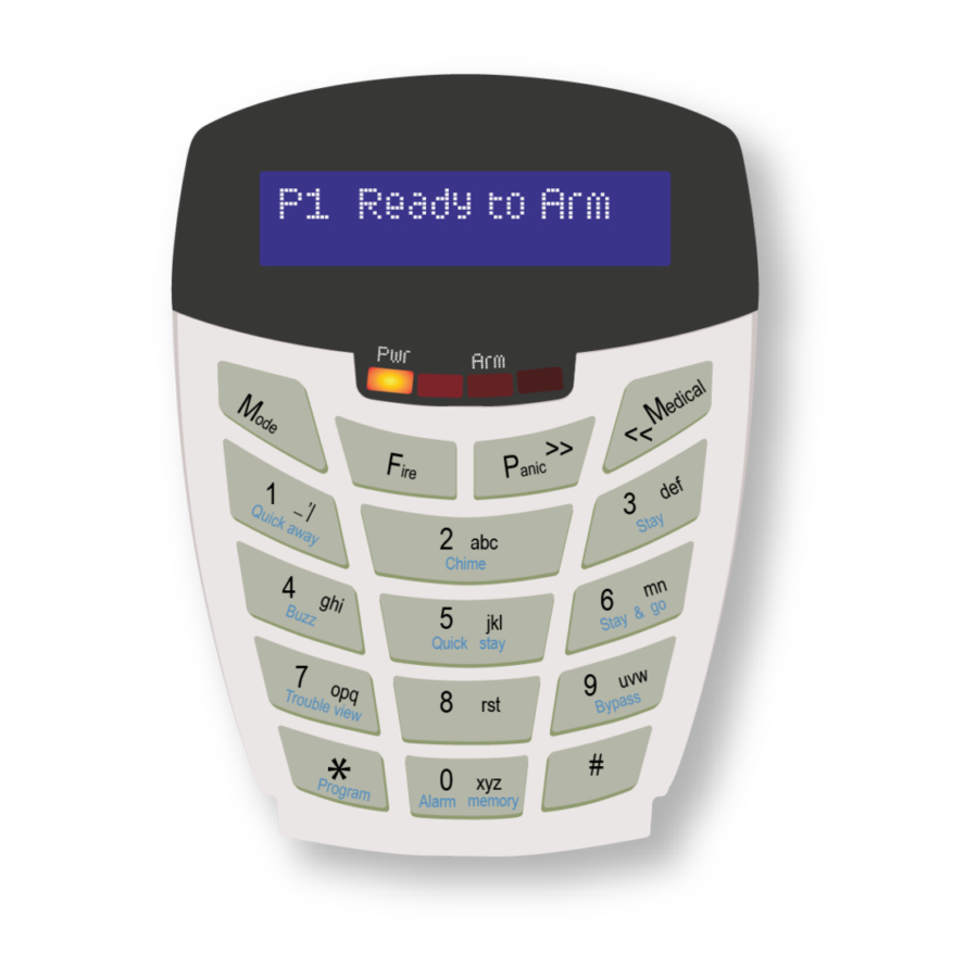
Keypads IDS X-Series Installer Manual 700-398-02O... - Page 6 New LCD KEYPAD LCD Display Power, Armed, Unarmed, Alarm Indicators Touch keys Keypad Indicator Icons Power indicator icon has two functions: When the icon is on, this indicates the keypad is powered up. Flashing indicates an issue has occurred and needs your attention. Armed icon indicates the system is armed either in ‘away’...
-
Page 7: Introduction To The Ids X-Series
Thank you for purchasing an IDS Alarm Panel. The IDS X-Series alarm is a versatile, Bylaw 25 compliant, expandable Alarm Panel. It comes in three versions, X8, X16 and X64. Both have up to 8 partitions and can have 8 keypads. The X16 can be expanded from 8 to16 zone, the X64 from 8 to 64 zones and the X8 only has 8 zones with no dialler. -
Page 8: Installation And Wiring
Remove the short/jumper once the Panel Status LED lights up (indicating power up), as leaving it on disables the low battery cut-out.* Figure 1: Connection Diagram Note: When using extra power supplies to power any peripheral connected to the keypad bus an IDS RS485 isolator (860-06- 0557) must be used. IDS X-Series Installer Manual 700-398-02O... -
Page 9: Installation Requirements
(P/N: 860-06-X-08S), 1 plug-in expander (P/N: 860-06-X-08PI) and 2 bus-wired output expanders may be added to the IDS X64 Alarm Panel. Zones 9-16 are reserved for the Plug-in Zone Expander module which may be used on the X16 as well. -
Page 10: Hardware Default Switch
If a new keypad was enrolled, go to location 243 to check the keypad’s ID (1-8). Solution If there are problems with device IDs on a complex installation, do not assign IDs randomly, rather, at the end of the installation, default all device IDs and then enrol them in sequence. -
Page 11: Defaulting Keypads
Wait for five seconds and ensure that the Panel Status LED on the panel is flashing, if the panel power was removed. Press the [#] key to allocate a new ID to the defaulted keypad. Keypad IDs are allocated incrementally. -
Page 12: Download Code
Download Code The Download Code, location 198, (in conjunction with the Installer Code) is required for download access via the IDS Download Software. The default Download Code is 9999 or 999999 for a 6-digit code. NOTE: It is possible to program location 34 to either allow or disallow defaulting of the Download Code. -
Page 13: Programming Quick Reference Guide
• READY is flashing. • [#] to exit and the READY LED will stop flashing. • The panel is now in standby mode. For a more detailed programming explanation, please see the X-Series training manuals IDS X-Series Installer Manual 700-398-02O... -
Page 14: Programming Location Summary
If you require a panic zone whose status can be viewed on a keypad, Do NOT use the dedicated panic as it cannot be viewed on a keypad. ➢ Zones 1-8 are onboard zones. ➢ Zones 9-16 are plug-in expander zones. (supported only by X16, X64) ➢ Zones 17-64 are expander zones. (supported only by X64) IDS X-Series Installer Manual 700-398-02O... - Page 15 2 references zones 9 to 16, location 3 references zones 17 to 24, etc. I.e. To program the defaulted zone types (Table 6) for the first 16 zones use the following: [INSTALLER CODE] [*] [1][*] reference zones 1 - 8 [0102040404040404][*] [2][*] reference zones 9 - 16 [0000000000000000][*] IDS X-Series Installer Manual 700-398-02O...
-
Page 16: Global Setup
Low Battery Monitoring Monitored Power Supply This trouble condition will be caused by the battery voltage dropping below 11.3V. ➢ Fuse Fail Monitoring This trouble condition indicates that the fuse on the monitored power supply has blown. IDS X-Series Installer Manual 700-398-02O... - Page 17 NOTE: If mains power is present, then the battery is monitored every 30 minutes and with no mains every minute. If the battery voltage drops below 10V, then the battery will cut-out if option 13 is enabled. If the battery voltage drops below 11V, then option 12 will be reported if it is enabled. IDS X-Series Installer Manual 700-398-02O...
- Page 18 This trouble condition will only clear once the battery voltage has been restored. ➢ Aux 12V Monitoring This trouble condition indicates that the fuse has blown, or that there is a fault This trouble condition will only clear once the fault has been restored. IDS X-Series Installer Manual 700-398-02O...
- Page 19 Option 4 in locations 221-228 (Extended Partition Options) must be enabled for the keypad lockout count to have an effect. [INSTALLER CODE] [*] [2] [0] [*] [KEYPAD LOCKOUT COUNT] [*] The valid data range is: 2 – 16. IDS X-Series Installer Manual 700-398-02O...
-
Page 20: Daylight Savings
Select the day of the week for Daylight Saving to commence, as per Table 14. Table 14: Day of Week Data Value Value Monday Friday Tuesday Saturday Wednesday Sunday Thursday [INSTALLER CODE] [*] [2] [6] [*] [DAY] [*] IDS X-Series Installer Manual 700-398-02O... -
Page 21: Miscellaneous- Advanced
Refer to Table 17 for the values that can be programmed. [INSTALLER CODE] [*] [3] [4] [*] [DOWNLOAD CODE DEFAULT DISABLE] [*] Table 17: Download Code Disable Data Value Action Enable Download code defaulting Disable Download code defaulting IDS X-Series Installer Manual 700-398-02O... - Page 22 Refer to Table 19 on page 22 for the available communication formats. [INSTALLER CODE] [*] [4] [1] [*] [COMMUNICATIONS FORMAT] [*] The valid data range is: 0 – 6. Refer to table 19 on page 22. NOTE: All telephone locations do not apply to the X8 IDS X-Series Installer Manual 700-398-02O...
- Page 23 The Call-back feature, when enabled, allows the download software/ to request that the panel call it back using the phone number as programmed into location 50. Table 21: Download Options Data; Default Action Fax Defeat Forced Answer Auto Pickup IDS X-Series Installer Manual 700-398-02O...
-
Page 24: Phone Numbers
Refer to Figure 2 , to see how telephone numbers work with split reporting. Figure 2: How Telephone Numbers Work Phone Numbers Split Reporting Split Reporting Module 1 Module 2 Tel 1 Tel2 Tel 3 Tel 4 EG: Base 1 Base 2 IDS X-Series Installer Manual 700-398-02O... -
Page 25: Zone Properties
If the panel is armed and a tamper condition occurs on the particular zone, an audible alarm condition will register and a tamper condition will be reported. IDS X-Series Installer Manual 700-398-02O... - Page 26 Buzz Profile 2 Zone always triggers PGM Buzz Profile 3 Reserved Buzz Profile 4 NOTE: Please see section 14 of the User manual for more information on how stay profiles and how to switch between them. IDS X-Series Installer Manual 700-398-02O...
-
Page 27: No Movement- Advanced
Auto ARM Days of the Week Medical Days of the Week Monday Monday Tuesday Tuesday Wednesday Wednesday Thursday Thursday Friday Friday Saturday Saturday Sunday Sunday All OFF (Arm Day Disabled) All OFF (Disarm Day Disabled) IDS X-Series Installer Manual 700-398-02O... -
Page 28: Security Codes
A value of [10] programmed into location 34 will prevent the download code from being defaulted when performing a hardware default. [INSTALLER CODE] [*] [1] [9] [8] [*] [NEW DOWNLOAD CODE] [*] NOTE: If the panel is defaulted, the download code will revert to 9999. The download code is 4-digits in length. IDS X-Series Installer Manual 700-398-02O... -
Page 29: Partition Options
Enabling this option will prevent the panel from being rearmed after an alarm condition has occurred. In order to re-arm the panel, the installer will be required to enter a valid installer code. If option 7 is set in location 16, an engineer reset trouble condition will also be displayed on the keypad. IDS X-Series Installer Manual 700-398-02O... -
Page 30: Delays
Enter a 4-digit entry delay period for each of the 8 partitions and program as a 32-digit string, followed by the [*] key. [INSTALLER CODE] [*] [2] [3] [1] [*] [PARTITION NO.] [*] [MMSS] [*] The valid data range is: 00m00s – 59m59s. Partition no. is: 1-8. IDS X-Series Installer Manual 700-398-02O... -
Page 31: Options To Configure Keypads
The Global Keypad Status will allow sixteen zones to be displayed regardless of the partition to which either the keypad or zones are assigned. On a LED keypad from the keypad start zone number plus 16 zones. On a LCD keypad from the keypad start zone number up to 64 zones. IDS X-Series Installer Manual 700-398-02O... -
Page 32: Axess Control
Sub location 2 deleting wireless devices Sub location 3 checking signal strength (Xwave only) Sub location 4 Supervision Time (Xwave only) Sub location 5 Xwave2 Zone Properties Please see the Xwave, IDS 700-589-02x or Xwave , 700-564-02x manual depending on your installation. Xwave associated outputs:... - Page 33 This code is reported when any external device attached to the keypad bus is restored. ➢ Sub-location 5 is Bus Peripheral Power/Battery Low This code is reported when a peripheral, on the bus, experiences a low power supply. IDS X-Series Installer Manual 700-398-02O...
- Page 34 Reserved sub-locations have a value of 00. [INSTALLER CODE] [*] [3] [0] [3] [*] [SUB-LOCATION] [*] [REPORTING CODE] [*] If any of the sub-locations are disabled here, then the reporting codes will not report – even if they are enabled IDS X-Series Installer Manual 700-398-02O...
-
Page 35: Zone Reporting Codes
Location 323 is zones 39-64 Enter a 2-digit reporting code for each of the 16 zones and program as a 32-digit string, followed by the [*] key. [INSTALLER CODE] [*] [LOCATION] [*] [ZONE NO.] [*] [REPORTING CODE] [*] IDS X-Series Installer Manual 700-398-02O... -
Page 36: Partition Reporting Codes
Enter a 2-digit reporting code for each of the 8 partitions and program as a 16-digit string, followed by the [*] key. [INSTALLER CODE] [*] [3] [3] [9] [*] [PARTITION NO.] [*] [REPORTING CODE] [*] If any of the sub-locations are disabled here, then the reporting codes will not report – even if enabled IDS X-Series Installer Manual 700-398-02O... -
Page 37: User Reporting Codes
Locations to enter reporting codes if you want to report when a user uses the quick stay arm key to arm, to the control room. This is for formats other than Contact ID and SIA. Default is 00. IDS X-Series Installer Manual 700-398-02O... -
Page 38: Programmable Outputs
Table 34 to view which zone corresponds to which keypad output. Output Output Output Output Keypad 1 Keypad 3 Keypad 5 Keypad 7 Keypad 2 Keypad 4 Keypad 6 Keypad 8 Table 34: Clear Programmable Keypad Outputs Data IDS X-Series Installer Manual 700-398-02O... -
Page 39: Partition Event Driven Outputs- Advanced
Alarm Restoral Programmable Output Event Disabled [00] Bypass Programmable Output Event Disabled [00] Forced Arm Programmable Output Event Disabled [00] Zone Tamper Programmable Output Event Disabled [00] Zone Tamper Restoral Programmable Output Event Disabled [00] IDS X-Series Installer Manual 700-398-02O... -
Page 40: Zone Programmable Output Events
Low Battery Restore Programmable Output Event Disabled [00] Auto Test Programmable Output Event Disabled [00] Download Programmable Output Event Disabled [00] Siren Tamper Programmable Output Event Disabled [00] Aux 12V Trouble Programmable Output Event Disabled [00] Reserved Disabled [00] IDS X-Series Installer Manual 700-398-02O... -
Page 41: Output Pulse Timing - Advanced
Enter a 4-digit time, [HHMM], for each of the 6 zone expanders output and program as an 8-digit string, followed by the [*] key. [INSTALLER CODE] [*] [LOCATION] [*] [OUTPUT NO.] [*] [HHMM] [*] The valid data range is: 00h00m – 23h59m, with 24h00m to disable.Output no. is: 1-2. IDS X-Series Installer Manual 700-398-02O... -
Page 42: Output Scheduling Off Time - Advanced
Table 39: Output Scheduling On/Off Days Data ON Days of the Week OFF Days of the Week Monday Monday Tuesday Tuesday Wednesday Wednesday Thursday Thursday Friday Friday Saturday Saturday Sunday Sunday All OFF (Arm Day Disabled) All OFF (Disarm Day Disabled) IDS X-Series Installer Manual 700-398-02O... -
Page 43: Event Reporting Options - Advanced
Telephone module 1 Wireless Detector Battery Low Telephone module 1 Wireless Detector Supervision fail Telephone module 1 Wireless Receiver Signal Jammed Telephone module 1 Wireless Detector RSSI Low Telephone module 1 AC Restored Telephone module 1 IDS X-Series Installer Manual 700-398-02O... - Page 44 Telephone module 1 Reserved Reserved LOCATION 589 Stay Zone Split Reporting Codes This is to choose which group of split reporting numbers to report to stay zone reporting when using, 4x2 reporting. Default is Telephone Module 1. IDS X-Series Installer Manual 700-398-02O...
-
Page 45: Touch Keypad Switch To Programmable Output Mapping
Location 650 Selecting Switch Toggle or Pulse Action When using the switch function on the IDS touch keypad and programmable outputs have been mapped to switches 1 – 9, an action must be selected for each switch mapped to an output. -
Page 46: Panel Information
Manual PGM mode can be done even if keypad is in armed state Panic zones can be bypassed if enabled in zone options location 101 to 164 New User Property -- Allow or disallow a user from bypassing zones (Option 10) IDS X-Series Installer Manual 700-398-02O... -
Page 47: Appendix
161 Loss of air flow Zone 375 Panic zone trouble Zone 162 Carbon Monoxide detected Zone 376 Hold-up zone trouble Zone 163 Tank level Zone 377 Swinger Trouble Zone 200 Fire Supervisory Zone 378 Cross-zone Trouble Zone IDS X-Series Installer Manual 700-398-02O... - Page 48 427 Access point Door Status Monitor trouble Zone 630 Schedule change Zone 428 Access point Request To Exit trouble Zone 631 Exception schedule change Zone 429 Access program mode entry User 632 Access schedule change Zone IDS X-Series Installer Manual 700-398-02O...
-
Page 49: Hardware Identification
Hardware Identification The new X series PCB has a larger memory chip on board to accommodate the new features and to distinguish between the old and new “512K” will be screened onto the PCB and will have a silver warranty sticker on the processor. -
Page 50: Trouble Display
Blown fuse on the monitored power supply The fuse protecting the battery has blown and needs to be replaced IDS X-Series Installer Manual 700-398-02O... - Page 51 Keypad Setup (Individual) ........31 Zone Key-switch .......... 9, 15, 29, 30 Buzz .............. 26 Lightning Protection ..........9 Entry/Exit ............. 26 Location Values ..........12 Stay .............. 26 locations ............14 Zone Properties..........25 IDS X-Series Installer Manual 700-398-02O...
- Page 52 Wherever possible, return only the PCB to Inhep Electronics Holdings as it is not necessary to return the enclosure for electronic swop outs. The IDS806 product is a product of IDS (Inhep Digital Security) and is manufactured by Inhep Electronics Holdings (Pty) Ltd.
Need help?
Do you have a question about the X Series and is the answer not in the manual?
Questions and answers