Table of Contents
Advertisement
Quick Links
Advertisement
Table of Contents

Related Manuals for Seat Arosa 2003


Summary of Contents for Seat Arosa 2003
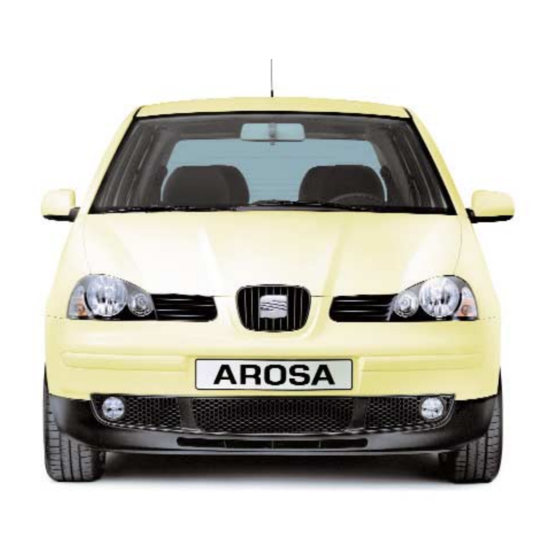
- Page 1 arosa Owner’s manual...
- Page 3 ON BOARD LITERATURE This o o wner’s M M anual and the Supplements provided should be read carefully so that you can quickly become familiar with the controls and operation of your vehicle. As well as care and regular maintenance, correct handling helps maintain the car’s value.
- Page 4 STRUCTURE OF THIS MANUAL You s s hould n n ote t t hese p p oints b b efore r r eading t t his O O wner’s M M anual Range o o f e e quipment Notes o o n d d irection It describes the largest possible range of Apart from exceptions, all notes on the equipment envisaged at the time of going...
- Page 5 Manual is divided into. Safety f f irst This chapter provides information on your vehicle’s passive safety fittings such as seat belts, Air Bags, child seats and safety and head rests. Handling i i nstructions This chapter provides information on the layout of the driver’s controls, the different seat adjustments,...
- Page 7 Introduction to the subject ... . . 1.2 Seat belts ......1.3 Air Bag system* .
- Page 8 AROSA in this chapter. We have detailed everything you need to know about, for example, seat belts, Air Bags, child seats, safety for children and head restraints. Please p p ay p p articular a a ttention t t o t t he notes a a nd w w arnings i i n t t his c c hapter –...
- Page 9 SAFETY FIRST Seat b b elts Why h h ave s s eat b b elts? It h h as b b een p p roven t t hat s s eat b b elts give g g ood p p rotection i i n a a ccidents. I I n most c c ountries, t t herefore, t t he w w ear- ing o o f s s eat b b elts i i s r r equired b b y l l aw.
- Page 10 As the vehicle occupants in our example The forces exerted on the body will are wearing no seat belts, their entire increase further at higher speeds, e.g. At kinetic energy can only be dispersed twice the speed the forces increase four-...
- Page 11 Somebody sitting in wheel, instrument panel or windscreen. the rear and not using a seat belt is endangering not only himself but also the Vehicle occupants who are not belted in occupants of the front seats.
- Page 12 These physical principles also apply, of course, to other types of accidents and to vehicles with the Air Bag System. This is why you must put on your seat belt before every journey, even if you are only going “just around the corner”. Please also ensure that your passengers are cor- rectly belted in.
- Page 13 Please t t ake n n otice o o f t t he w w arning notes o o n t t he n n ext p p age. SEAT BELTS ––––––––––––––––––––––––––––––––––––––––––––––––––––––––––––––––––––––––––––––...
- Page 14 Note otherwise n n ot e e ngage p p roperly. In some export countries seat belt func- • You s s hould c c heck t t he c c ondition tions could differ from the 3 point or lap of y y our s s eat b b elts r r egularly.
- Page 15 • Push the tongue into the locking part of Seat b b elts c c an o o nly g g ive t t heir m m ax- the seal until it engages audibly (pull t t o imum p p rotection i i n a a n a a ccident i i f test!).
- Page 16 1.10 ––––––––––––––––––––––––––––––––––––––––––––––––––––––––––––––––––––––––––––...
- Page 17 • After adjusting, pull the belt with a jerk to ensure that the relay fitting is properly engaged. Note The seat height adjustment* can also be used to adjust belt routing on front seats. SEAT BELTS –––––––––––––––––––––––––––––––––––––––––––––––––––––––––––––––––––––––––––– 1.11...
- Page 18 The tongue will then spring out. Pass the tongue towards the door by hand so that the retractor can roll the belt up properly. A plastic knob in the belt holds the tongue in a convenient position. 1.12 –––––––––––––––––––––––––––––––––––––––––––––––––––––––––––––––––––––––––––– SEAT BELTS...
- Page 19 • It is of utmost importance to observe the relevant safety regulations when the vehicle or components of the system are scrapped. Technical Service Centres are familiar with these regulations and can provide details. SEAT BELTS –––––––––––––––––––––––––––––––––––––––––––––––––––––––––––––––––––––––––––– 1.13...
- Page 20 A A ir B B ag should b b e m m ade o o perational a a gain b b y a T T echnical S S ervice C C entre. 1.14 –––––––––––––––––––––––––––––––––––––––––––––––––––––––––––––––––––––––––––– SEAT BELTS...
- Page 21 Also b b ear i i n m m ind t t he i i nstructions from t t he " " Seat b b elts" c c hapter. AIR BAG –––––––––––––––––––––––––––––––––––––––––––––––––––––––––––––––––––––––––––––––...
- Page 22 SAFETY FIRST Air B B ag f f unctions a a re c c ontrolled e e lec- tronically: • Each time that the ignition is turned on, the Air Bag warning light will light for about 3 seconds. • If at least one of the Air Bag devices is deactivated, the warning light will flash for approx.
- Page 23 When the system is triggered, the bags seat belts. are inflated by gas opening in front of the driver and passenger. It is not possible to define globally when...
- Page 24 Technical Service Centres are famil- front-seat o o ccupants a a nd t t he e e ffec- iar with these regulations. tive r r ange o o f t t he A A ir B B ags.
- Page 25 SAFETY FIRST Warning n n otes Warning • Any r r epairs t t o t t he s s ide A A ir B B ag, such a a s t t he r r emoval o o r a a ssembly of a a ny s s ystem c c omponent i i n c c on- nection w w ith a a ny o o ther r r epair w w ork (e.g.
- Page 26 SAFETY FIRST • • Only l l ight a a rticles o o f c c lothing Any d d amage t t o t t he o o riginal s s eat should b b e h h ung o o n t t he c c oat h h ooks. covers o o r t t o t t he s s eam i i n t t he s s ide No h h eavy o o r s s harp-edged i i tems Air B B ag m m odule a a rea m m ust b b e...
- Page 27 • if it is not possible to keep a minimum child seat uniquely o o n t t he r r ear p p assen- distance of 25 cm between the center of ger s s eat, and to avoid the need to deac- the steering wheel and the breastbone tivate the passenger Air Bag.
- Page 28 A A ir B B ag s s ystem i i s to u u se a a s s uitable c c hild r r estraint s s ys- triggered d d uring a a n a a ccident.
- Page 29 L – Adequate for retention systems with systems officially authorized with ISOFIX anchoring. this age group. (Universal retention X – Seat space not adequate for children systems are those fixed by the adult of this age group. safety belt). UF – Adequate for the universal retention...
- Page 30 SAFETY FIRST Note Child r r estraint s s ystems t t ested a a ccord- ing t t o E E CE-R 4 4 4.03 s s tandard a a re clearly m m arked w w ith t t he E E CE-R 4 4 4.03 test m m ark ( ( capital E E i i n a a c c ircle a a nd a a number w w hich i i ndicates t t he c c ountry of t t he n n orm, i i .e.
- Page 31 SAFETY FIRST B1S-002P B1S-003P Group I I Group I I I For babies and small children weighing For children weighing between 15-25 kg. between 9-18 kg. Best suited are child Best suited are child seats combined with seats with safety board – see illustration 3- point safety belts.
- Page 32 1.50 m (5’) tall. Best suited should y y ou t t ransport c c hildren o o r are seat cushions combined with the 3- infants i i n t t he v v ehicle, b b y c c arrying point seat belt.
- Page 33 Centre. seat b b elts f f itted i i n t t he v v ehicle. T T he bolts m m ust b b e s s crewed i i nto t t he hole f f or t t he c c omplete l l ength a a nd tightened t t o 4 4 0 N N m.
- Page 34 ISOFIX s s ystem There are four attachment rings (see arrows) on the body work between the chassis and the cushions of the rear seat. You can use these rings to attach a maxi- mum of two child seats with the ISOFIX system.
- Page 35 – At the same time push the seat back as resting o o n t t he i i nstrument p p anel o o r far as possible.
- Page 36 Correctly adjusted head restraints together with the seat belts offer effective protection. It is also possi- ble to set the angle of the front head restraints. Adjusting h h eight •...
- Page 37 Doors ..... 2.17 Rear seat ....2.56 Central locking* .
- Page 38 HANDLING INSTRUCTIONS Table ––––––––––––––––––––––––––––––––––––––––––––––––––––––––––––––––––––– INSTRUMENT PANEL...
- Page 39 HANDLING INSTRUCTIONS AR0-005A INSTRUMENT PANEL –––––––––––––––––––––––––––––––––––––––––––––––––––––––––––––––––––––...
- Page 40 HANDLING INSTRUCTIONS Position Page Position Page 1 - Switch for electric windows*..2.29 22 - Gear lever (manual gearbox)..2.76 2 - Central locking button* ... 2.20 Selector lever (automatic gearbox)* ......2.76-2.77 3 - Door lock release lever .... 2.17 23/27 - Heat seating controls ..2.38 4 - Remote controlled outside...
- Page 41 HANDLING INSTRUCTIONS Instruments AR0-006 The arrangement of the instruments 1 – – F F uel l l evel depends on the model and the engine fit- This gauge works when ignition is ted. switched on. Page The tank holds about 34 litres (approx. 1 –...
- Page 42 HANDLING INSTRUCTIONS AR0-007 AR0-008 3 – – D D igital c c lock 4 – – C C oolant t t emperature Two buttons are used to set the time. The The gauge starts to work when ignition is hours are set with the left button (arrow 1) switched on.
- Page 43 HANDLING INSTRUCTIONS c – – W W arning l l amp If the lamp flashes and a tone is heard at the same time when driving, first check the coolant temperature being displayed. If the needle is in the normal zone, top the coolant up at the next opportunity.
- Page 44 HANDLING INSTRUCTIONS Service I I nterval D D isplay* Notes • Only the desired service may be reset. If a service is due, one of the following The date for a service would otherwise be services will appear in the lower speedo- incorrect.
- Page 45 9 – Engine management (petrol engine)/Preheating (Diesel Page engine) ........2.12 1 – Fuel level/Reserve level ...2.10 10 – Brake system......2.12 2 – Seat belt warning lamp 11 – Anti-locking brake system ..2.10 (ABS)* ........2.13 3 – Alternator ........2.10 12 – Air Bag system* .......2.14 4 –...
- Page 46 See the "Engine If the seat belt is not fastened an acoustic oil" chapter. signal will sound after switching on the...
- Page 47 HANDLING INSTRUCTIONS 5 – – S S ide l l ights – Exercise c c aution w w hen o o pening The warning lamp comes on when the the c c oolant e e xpansion t t ank! side lights are switched on. When t t he e e ngine i i s h h ot t t he c c ool- ing s s ystem i i s u u nder p p ressure –...
- Page 48 HANDLING INSTRUCTIONS 7 – – M M ain b b eam Note If w w hile d d riving a a f f ault o o ccurs i i n t t he The warning lamp comes on when main diesel e e ngine m m anagement s s ystem, beam is on or when the headlight flasher this i i s i i ndicated b b y t t he w w arning l l amp...
- Page 49 HANDLING INSTRUCTIONS AR0-010 11 – – A A nti-locking b b rake Warning system ( ( ABS)* If b b oth w w arning l l amps l l ight u u p, This warning lamp monitors the ABS* sys- you m m ust s s top t t he v v ehicle i i mmedi- tems.
- Page 50 HANDLING INSTRUCTIONS 12 – – A A ir B B ag system* 14 – – I I ndicators When turning on the key in the ignition, The right or left arrow will flash depending the warning light lights up for about upon which direction has been selected.
- Page 51 Key t t ag The key tag contains the key number, which is needed to obtain replacement keys. SEAT dealers can only order replace- ment keys if they have this number. Note The k k ey t t ag s s hould b b e k k ept s s eparately as k k eys c c an o o nly b b e r r eplaced u u sing this n n umber.
- Page 52 Note LEO-005 The engine can thus only be started with a correctly coded Genuine SEAT key. Vehicles with remote control* have two Trouble free operation of your vehicle can keys. One is a conventional key (see pre- only be guaranteed when using genuine vious page).
- Page 53 HANDLING INSTRUCTIONS Doors From t t he o o utside the driver door can be From i i nside all the doors can be locked opened with the key. by pressing down the locking knobs. When o o pening, the locking knobs move Warning By l l ocking t t he d d oors, t t his m m ay p p re- If the key is held in the opening position...
- Page 54 For cars equipped with electric powered Locking p p oints o o n t t he v v ehicle windows the front windows will open from the driver’s seat by keeping the key in the outside: open position Driver’s door or the radio-frequency remote control*.
- Page 55 HANDLING INSTRUCTIONS Locking All doors and tailgate will be locked. Neither the lock safety system nor the • To lock your vehicle turn t t he k k ey to the anti-theft alarm* will be activated (see the lock position once in the lock of the dri- "Anti-theft alarm system"...
- Page 56 HANDLING INSTRUCTIONS Notes If the vehicle is locked using the button, it is possible to open the doors separately. To do this, pull the door until the locking knob moves upwards. You can now open the door by pulling the release lever again.
- Page 57 HANDLING INSTRUCTIONS • Once t t he v v ehicle h h as b b een locked w w ith t t he r r adio w w ave r r emote control o o r w w ith a a r r egular k k ey t t he central l l ocking k k nob b b ecomes inactive.
- Page 58 HANDLING INSTRUCTIONS Tailgate IB9-015 IB9-016 To o o pen the tailgate when the key slot is Tailgate vertical (see illustration), pull the handle • When the key slot is vertical (a) the tail- and lift the tailgate. gate/boot lid is locked or unlocked auto- To c c lose pull the tailgate down using one matically by the central locking system.
- Page 59 HANDLING INSTRUCTIONS Anti-theft a a larm s s ystem* With the anti-theft alarm, break-in The alarm will be triggered if, with the attempts and theft of the vehicle are ren- vehicle locked, one of dered more difficult. The system triggers •...
- Page 60 HANDLING INSTRUCTIONS Note • If, after deactivating the volumetric sensor, the door is locked with the remote control or manually with the key in the door lock within less than 30 seconds the volumetric sensor is deactivated even though all other anti-theft alarm functions remain activated.
- Page 61 HANDLING INSTRUCTIONS AR0-042 Sensors The sensors for the interior monitoring system are located next to the rear roof base (see arrows). Do not cover the sen- sors otherwise correct functioning of the interior monitoring system is hindered. OPENING AND CLOSING ––––––––––––––––––––––––––––––––––––––––––––––––––––––––––––––––...
- Page 62 HANDLING INSTRUCTIONS Radio-frequency r r emote c c ontrol k k ey* The following functions can be operated using the radio wave remote control. The key is not needed. – Locking and unlocking central locking system. – Deadlock and anti-theft* warning sys- tems on/off.
- Page 63 HANDLING INSTRUCTIONS Notes When the close or open buttons are pressed, a warning lamp will flash in the key. If this warning lamp does not flash, the battery in the key may be empty. In this case a Technical Service Centre should check and/or change the battery.
- Page 64 HANDLING INSTRUCTIONS Synchronization Uncoded keys can be obtained at SEAT Official Service Centers. These keys, how- If the vehicle fails to open when the radio ever, must be synchronized by a SEAT transmitter button is pressed, it could be Official Service Center as the code for the...
- Page 65 An additional switch has been fitted in the back f f unction. armrest of the passenger seat. If you brielfy press or pull the switch as Operating e e lectric w w indows w w ith...
- Page 66 HANDLING INSTRUCTIONS Opening Warning Press and briefly hold the front edge of • Always r r emove t t he i i gnition k k ey the respective button and the window will when l l eaving t t he v v ehicle – – e e ven i i f open fully (automatic window opening).
- Page 67 HANDLING INSTRUCTIONS The r r oll-back f f unction* Note (There may be slight operative differences If you wait for longer than 10 seconds in some versions or in vehicles for certain between the individual steps, the window countries). will open again on switch operation. 1 –...
- Page 68 HANDLING INSTRUCTIONS Opening Notes Press the front edge of the respective but- The automatic opening/closing function* ton. on the driver door windows will not function after t t he v v ehicle b b attery h h as b b een d d is- Closing connected/reconnected.
- Page 69 HANDLING INSTRUCTIONS Side o o pening r r ear w w indows* B6X-029D B6X-030D Opening Closing Pull the lever in the direction of the arrow Pull the lever in the direction of the arrow and then push the lever outwards, until it and then push the lever backwards until it fits into place.
- Page 70 HANDLING INSTRUCTIONS Sliding/tilting r r oof* Closing ( ( A) To close turn the switch to position A. The sliding roof is equipped with a roll- back f f unction. If the roof is hindered in closing by stiffness or by an obstacle, it will open again immediately.
- Page 71 HANDLING INSTRUCTIONS B6X-100D B6X-101D Note Emergency o o peration The sun screen will open automatically as If the system is faulty, the roof can also be a protection from excessive sun rays when closed manually: the glass roof is opened. If you wish, you •...
- Page 72 HANDLING INSTRUCTIONS Switches Note If lights are not switched off and the igni- tion key is removed, a buzzer* will sound when the driver’s door is open. Front f f og l l ights* With lighting switch in side light or dipped/main beam position pull switch out to first detent.
- Page 73 HANDLING INSTRUCTIONS 2 – – I I nstrument l l ighting When the lights are on, the level of the instrument lighting can be set to any intensity by turning the knurled wheel next to the switch. 3 – – H H eadlight r r ange c c ontrol* With the electrical range control the head- light settings can be matched exactly to the load condition of vehicle.
- Page 74 HANDLING INSTRUCTIONS 7 – – E E lectronic S S tability Program ( ( ESP)* The ESP connects automatically when starting the engine. If required, it can be switched on or off by using the appropri- ate key (7). The warning light will go on when it is off. See the "Warning lamps"...
- Page 75 HANDLING INSTRUCTIONS Sun v v isors B6X-016D The sun visors can be pulled out of the side mountings and swung towards the doors. The make-up mirrors on the rear side of the sun visors also have a cover flap*. There is a small sun visor* over the rear view mirror, which can be pulled out in the direction of the arrow (see illustra- tion).
- Page 76 HANDLING INSTRUCTIONS Indicators a a nd d d ipped b b eam l l ever Headlight f f lasher Pull the lever towards the steering wheel to the pressure point – the main beam warning lamp will light up. Parking l l ights The parking lights only work when igni- tion is switched off.
- Page 77 HANDLING INSTRUCTIONS Interior l l ights The interior light will go out: • approx. 20 seconds after the doors have been closed. • as soon as the vehicle has been locked from the outside. • as soon as the ignition has been switched on.
- Page 78 HANDLING INSTRUCTIONS Windscreen w w ipers a a nd w w ashers Warning The w w indshield w w iper b b lades m m ust be i i n p p erfect c c ondition t t o e e nsure good v v isibility ( ( see t t he "...
- Page 79 HANDLING INSTRUCTIONS Rear w w indow • Quick w w ipe If you push the button to the pressure point in the direction of the arrow 5, the rear windscreen wiper will wipe once. • Intermittent w w ipe o o f r r ear w w iper If you push the button in the direction of arrow 5 past the pressure point, the wiper will begin to work every six seconds...
- Page 80 HANDLING INSTRUCTIONS Wiper b b lades If t t he w w iper b b lades d d rag, i i t m m ay b b e Warning caused b b y o o ne o o f t t he f f ollowing: •...
- Page 81 HANDLING INSTRUCTIONS B6X-013D Changing w w iper b b lades Taking t t he w w iper b b lade o o ff • Hinge the wiper arm up and position the blade perpendicular to the wiper arm. • Press the retaining spring in the direc- tion of arrow A.
- Page 82 HANDLING INSTRUCTIONS Rear-view m m irrors Adjusting m m irrors The rear view mirrors should always be adjusted properly before moving off so that good vision to the rear is obtained. Anti-dazzle i i nside m m irror The lever on the lower edge of the mirror should be pointing to the rear when the basic setting is made.
- Page 83 HANDLING INSTRUCTIONS Note f f or v v ehicles w w ith c c onvex o o r aspherical o o utside m m irrors * * Convex (curved outwards) mirrors enlarge the field of view but they make objects look smaller. These m m irrors a a re only o o f l l imited u u se i i n e e stimating h h ow far a a way a a f f ollowing v v ehicle i i s.
- Page 84 – Backrest in an upright position. – Place the feet in the footwell in a com- fortable position. – At the same time push the seat back as far as possible. 2.48 ––––––––––––––––––––––––––––––––––––––––––––––––––– SEATS AND LUGGAGE COMPARTMENT...
- Page 85 effective.
- Page 86 To switch heating off, turn knurled wheel to the basic position (0). Warning 8 – – Seat h h eating* f f or r r ight • For s s afety r r easons t t he h h eight o o f seat the d d river’s s s eat m m ust o o nly b b e...
- Page 87 To remove, pull restraints up to the stop, size of the person in the seat. Correctly press button (arrow) and at the same time adjusted h h ead r r estraints t t ogether w w ith take restraints out.
- Page 88 HANDLING INSTRUCTIONS Adjustable s s teering c c olumn* AR0-020 The steering wheel height can be adjusted as required. To do this pull the lever on the left of the steering column down and move the steering wheel to the desired position.
- Page 89 HANDLING INSTRUCTIONS Pedals Luggage c c ompartment The m m ovement o o f t t he p p edals m m ust n n ot In the interests of good handling ensure be r r estricted! that the load (persons and luggage) is distributed evenly.
- Page 90 The lashing eyes comply with Standard must w w ear t t heir s s eat b b elts p p roperly DIN 75410. fastened. S S ee t t he " " Seat b b elts" chapter. • You s s hould n n ever d d rive w w ith t t he...
- Page 91 HANDLING INSTRUCTIONS Luggage c c ompartment c c over Clothing can be placed on the shelf behind the rear backrests. Note Please note that the field of vision of the rear view mirror can be obstructed by arti- cles of clothing. Warning When t t he v v ehicle i i s m m oving n n o animals o o r h h eavy i i tems a a re t t o b b e...
- Page 92 Folding s s eat b b ench d d own • Press the seat up in the area of the recess (arrow 1) and fold the cushion for- ward in the direction of the arrow (2) – see left illustration.
- Page 93 HANDLING INSTRUCTIONS B11-015D B11-016D • Press the release lever in the direction of the arrow – both release levers at the same time on one-piece backrests – and fold the backrest forwards. • To avoid noises and or wear and tear to the seatbelts, the tongues of the rear seatbelts should be placed in the slots in the side mouldings.
- Page 94 (arrow 5). • Remove the head restraints from the floor recesses. • Fold the seat cushion back and push the cushion under the belt locks to the rear. Then press the cushion down at the front. •...
- Page 95 HANDLING INSTRUCTIONS Roof r r ack* When loads are to be carried on the roof, the following should be noted: • As the rain channels are moulded into the roof for streamlining reasons, the nor- mal type of roof rack cannot be used. To avoid risks we advise that only the cross bars provided by the factory are used.
- Page 96 HANDLING INSTRUCTIONS Roof l l oad The p p ermissible r r oof l l oad ( ( including the c c arrier s s ystem) o o f 5 5 0 k k g i i n t t otal and t t he m m aximum p p ermissible w w eight of t t he v v ehicle m m ust n n ot b b e e e xceeded –...
- Page 97 HANDLING INSTRUCTIONS Drink c c an h h older* Ashtrays AR0-021 AR0-022 Remove The illustration shows the open drink can holder in the central console. Open ashtray, grip ashtray on the sides (see arrow) and remove. Warning Place Do n n ot p p lace a a ny h h ot d d rinks, s s uch as c c offee o o r t t ea, i i n t t he d d rink c c an Place ashtray on the insert guides and holder w w hile t t he v v ehicle i i s i i n...
- Page 98 HANDLING INSTRUCTIONS Cigarette l l ighter/ Electric s s ocket Stowage b b ox The cigarette l l ighter is switched on by You will find different stowage boxes pushing in the element. When the heating inside the vehicle. element glows, the lighter springs out Warning automatically –...
- Page 99 HANDLING INSTRUCTIONS Heating a a nd v v entilation Warning • Clear v v ision, w w hich c c ontributes to r r oad s s afety, c c an o o nly b b e g g uaran- teed i i f a a ll w w indows a a re f f ree o o f i i ce, snow a a nd m m ist.
- Page 100 HANDLING INSTRUCTIONS AR0-024 Air v v ents By swinging the complete outlet grille of vents 3 and 4 the air flow can be moved Depending on the position of rotary regu- vertically. lator A heated or unheated fresh air flows When the knurled disc in the grille is from all vents.
- Page 101 HANDLING INSTRUCTIONS Defrosting w w indscreen a a nd s s ide windows • Rotary switch B to stage 3. • Rotary regulators A and C turned fully to right. • Vents 3 closed • Adjust vents 4 so that additional warm air can be directed to the side windows.
- Page 102 HANDLING INSTRUCTIONS AR0-024 Heating i i nterior c c omfortably or to ..........When the windows are clear and the If the windscreen mists over again, desired temperature has been reached we the rotary regulator can also be turn- recommended the following settings: ed between ........
- Page 103 HANDLING INSTRUCTIONS Air c c onditioning* Ventilation ( ( fresh a a ir o o peration) Warning With the following settings, unheated • Clear v v ision, w w hich c c ontributes fresh air flows from vents 3 and 4: to r r oad s s afety, c c an o o nly b b e g g uaran- •...
- Page 104 HANDLING INSTRUCTIONS Rotary s s witch B B – – B B lower The air flow can be regulated in four stages. In position 0, the blower and air condi- tioner are switched off. To prevent contami- nated air (smells) entering the vehicle inte- rior, press button E (air recirculation).
- Page 105 HANDLING INSTRUCTIONS Button E E – – A A ir r r ecirculation Air recirculation is selected by pressing this button. A warning lamp lights up in the button. Air recirculation is switched off by press- ing the button again. The warning lamp then goes out.
- Page 106 HANDLING INSTRUCTIONS AR0-026 Air v v ents By swinging the complete outlet grille of vents 3 and 4 the air flow can be moved Depending on the position of rotary regu- vertically. lator A and buttons D, and E, heated or When the knurled disc in the grille is unheated fresh air or cooled air flows rotated to and fro the air flow direction is...
- Page 107 HANDLING INSTRUCTIONS Heating i i nterior a a s q q uickly a a s possible • Rotary switch B to stage 3. • Rotary regulator A fully to right. • Rotary regulator C to ....• Vents 3 closed. •...
- Page 108 HANDLING INSTRUCTIONS Heating i i nterior c c omfortably When the windows are clear and the desired temperature has been reached we recommend the following settings: • Rotary switch B at stage 1 or 2. • Rotary regulator A at the desired heat output.
- Page 109 HANDLING INSTRUCTIONS Maximum c c ooling Ventilation ( ( fresh a a ir o o peration) • All windows and sliding/tilting roof* With the following settings, unheated closed. fresh air flows from vents 3 and 4: • • Switch on air conditioner by pressing Switch off air conditioner by pressing button D.
- Page 110 HANDLING INSTRUCTIONS Using a a ir c c onditioner e e conomically • Odours caused by a build-up of natural In cooling operation the air conditioner com- deposits in the vaporiser can occur if the pressor places demands on the engine and air conditioner has not been used for therefore influences the fuel consumption.
- Page 111 HANDLING INSTRUCTIONS Operating f f aults • If y y ou t t hink t t he a a ir c c onditioning • Should the air conditioner not work at may b b e d d amaged, s s witch i i t o o ff a a nd any time, either: have i i t c c hecked i i mmediately a a t a a Technical S S ervice C C entre.
- Page 112 HANDLING INSTRUCTIONS Manual g g earbox Automatic g g earbox* AR0-027 AR0-028 Reverse gear may only be engaged when Driving p p rogrammes the vehicle is stationary. When engine is The gearbox management is fitted with running, depress clutch fully and wait a several driving programmes.
- Page 113 HANDLING INSTRUCTIONS The downward shift occurs at a higher Note rate of revolutions than in the economy Depending on road resistance, for exam- programmes. ple when trailer towing or on uphill The gear box is self adapting, and contin- stretches, a programme is automatically uously selects the most suitable gear pro- selected which provides more power by gramme.
- Page 114 HANDLING INSTRUCTIONS R – – R R everse g g ear The reverse gear should only be engaged when the vehicle is stationary and with the engine idling. Before engaging the position “R” from the positions “P” or “N” the brake pedal must be depressed and the lock button in the selector lever han- dle must also be pressed.
- Page 115 HANDLING INSTRUCTIONS 2 – – P P osition f f or s s teep h h ills Kick-down d d evice This selector lever position is suitable for The kick-down device gives maximum long climbs and descents. acceleration. When the accelerator pedal is pressed right down past the full throttle The 1st and 2nd gears are shifted up and position, depending on road speed and...
- Page 116 HANDLING INSTRUCTIONS Warning When t t he e e ngine i i s r r unning i i t i i s necessary t t o h h old t t he v v ehicle w w ith the f f oot b b rake i i n a a ll g g ears. Because w w ith a a n a a utomatic g g ear- box t t he t t ransfer o o f p p ower i i s n n ot fully i i nterrupted e e ven a a t i i dling...
- Page 117 HANDLING INSTRUCTIONS Stopping Tow s s tarting When the vehicle is stopped for a short On vehicles with automatic gearbox the period, for example at traffic lights, it is engine cannot be started by towing or only necessary to apply the brakes. It is pushing the vehicle –...
- Page 118 HANDLING INSTRUCTIONS Handbrake Warning • To p p revent t t he v v ehicle f f rom rolling a a way i i nadvertently, y y ou should a a lways a a pply t t he h h and- brake f f irmly a a fter t t he v v ehicle h h as come t t o a a c c omplete s s top.
- Page 119 HANDLING INSTRUCTIONS Ignition l l ock Warning • Do n n ot w w ithdraw k k ey f f rom l l ock until v v ehicle i i s s s tationary! T T he steering l l ock c c ould b b e u u ninten- tionally e e ngaged.
- Page 120 HANDLING INSTRUCTIONS For a a ll v v ehicles: Position 1 1 : To lock t t he s s teering w w heel withdraw key and turn wheel until you hear the locking pin engage. Note If lights or turn signals are not switched off, a buzzer* will sound, after the ignition key has been removed, when the driver’s door is open.
- Page 121 HANDLING INSTRUCTIONS Starting t t he e e ngine Do n n ot w w arm e e ngine u u p b b y r r un- General n n otes ning i i t w w ith v v ehicle s s tationary. Warning Drive o o ff s s traight a a way.
- Page 122 HANDLING INSTRUCTIONS Petrol e e ngines Diesel e e ngines These engines are equipped with a petrol Glow p p lug s s ystem injection system that automatically sup- After switching to the driving position plies the correct fuel/air mixture at all (ignition on) the required warm-up time is ambient temperatures.
- Page 123 HANDLING INSTRUCTIONS Starting a a w w arm e e ngine • When the warning lamp goes out, start The glow plug lamp does not come on – the engine immediately. the engine can be started straight away. If the engine does not start, repeat pre- glow and try starting it again as Starting a a fter r r unning o o ut o o f f f uel described.
- Page 124 HANDLING INSTRUCTIONS Stopping t t he e e ngine • • Valid f f or a a ll e e ngines: Valid f f or a a ll v v ersions w w ith c c atalytic converter*: When e e ngine h h as b b een r r unning f f ast for a a l l ong t t ime, l l et i i t i i dle f f or a a bout Do n n ot s s witch o o ff t t he i i gnition w w hile 2 m m inutes b b efore s s topping.
- Page 125 INDEX FILLING THE TANK CHECKING AND REFILLING Engine bonnet ....3.32 Filling the tank ....3.2 Engine compartment .
- Page 126 TIPS AND MAINTENANCE Filling t t he t t ank AR0-031 AR0-032 Filling t t he t t ank When tank cap has been taken off it can be placed on the tank flap – see illustra- The filler neck is in the rear right side tion.
- Page 127 TIPS AND MAINTENANCE Notes Any fuel spillage should be wiped off the paint finish immediately, as the paint could otherwise be damaged, especially if it is RME (“biodiesel”) fuel. On v v ehicles w w ith a a c c atalytic c c onverter, never d d rive u u ntil t t he f f uel t t ank i i s c c om- pletely e e mpty.
- Page 128 TIPS AND MAINTENANCE Petrol In the chapter “Technical Data” and on Petrol a a dditives the inside of the tank flap you will find The quality of the fuel has a decisive influ- information on the correct octane rating ence upon the running behavior, perfor- for your engine.
- Page 129 TIPS AND MAINTENANCE Diesel Diesel fuel must correspond to DIN EN 590. • Exhaust gas contains less no l l ower t t han 4 4 9. – carbon monoxide RME f f uel ( ( “diester”) – hydrocarbons – particles (i.e. soot) According to norm DIN 51 606 than with conventional diesel fuel.
- Page 130 TIPS AND MAINTENANCE Driving i i n t t he w w inter Pre-heating t t he f f ilter If you use summer diesel when the out- The vehicle is equipped with a pre-heating side temperature is below 0°C, faults may installation for the filter that preserves the occur, as the fuel becomes too thick safety of the fuel installation up to a tem-...
- Page 131 TIPS AND MAINTENANCE Brakes General n n otes Overheating o o f t t he b b rakes • Brake lining wear depends to a large Warning extent on traffic conditions and driving • Never l l et t t he b b rakes “ “ rub” b b y style.
- Page 132 TIPS AND MAINTENANCE Servobrake How t t he A A BS* s s ystem w w orks An automatic check is made when a Warning speed of approx. 6 km/h is reached. The s s ervo i i s o o perated b b y a a v v acuum When this happens a pumping noise can which i i s o o nly g g enerated w w hen t t he be heard.
- Page 133 TIPS AND MAINTENANCE Electronic D D ifferential L L ock ( ( EDL)* Vehicles with anti-lock brakes (ABS)* can To ensure that the brake disc of the also be equipped with an electronic dif- braked wheel does not overheat, the EDL ferential lock.
- Page 134 TIPS AND MAINTENANCE Power s s teering* Do not keep the steering wheel fully turned more than 15 seconds when the engine is switched on, as the hydraulic oil will be heated to a high temperature by the servo pump. This c c ould d d amage t t he p p ower s s teer- ing s s ystem.
- Page 135 TIPS AND MAINTENANCE The f f irst 1 1 ,500 k k m – a a nd a a fterwards Running-in From 1 1 000 – – 1 1 500 k k m During the first few operating hours the The speed can be gradually increased to engine internal friction is higher than the road or engine maximum.
- Page 136 TIPS AND MAINTENANCE Cleaning t t he e e xhaust f f umes The p p erfect f f unctioning o o f t t he c c lean- Warning ing s s ystem f f or e e xhaust f f umes is of •...
- Page 137 TIPS AND MAINTENANCE Environment-friendly a a nd e e conomical d d riving Three factors determine the fuel con- sumption, the burden on the environment and the wear on the engine, brakes and tyres: • The personal driving style. • The individual conditions of the use of the car.
- Page 138 TIPS AND MAINTENANCE Suggestion 4 4 Decrease i i dling It is worth switching off the engine in traffic jams, at railroad crossings and at traffic lights with a long red light. The sav- ings in fuel after 30-40 seconds with the engine switched off is higher than the fuel used to switch the engine on again.
- Page 139 TIPS AND MAINTENANCE Suggestion 7 7 Check t t he t t yre p p ressure Make sure that the tyres have always ade- quate pressure. Even half a bar less increases the level of fuel consumption by 5 percent. If the pressure is not correct, the tyres wear out faster due to an exces- sive deformation and overheating which, in turn, will decrease the driving perfor-...
- Page 140 TIPS AND MAINTENANCE Suggestion 9 9 Suggestion 1 1 0 Save e e lectricity Written c c heck-up The alternator generates electricity while If you wish to reduce fuel consumption driving. The more electricity is used, the keep a trip book. It is not much work and higher the fuel consumption.
- Page 141 TIPS AND MAINTENANCE Trailer t t owing The vehicle is intended mainly for the transportation of persons and luggage. However it can also be used to tow a trailer if fitted with the appropriate techni- cal equipment. Towing a a t t railer n n ot o o nly d d emands more f f rom t t he c c ar, b b ut f f rom t t he d d river too.
- Page 142 TIPS AND MAINTENANCE Operations i i nstructions • While observing the permissible trailer • If you drive without a trailer remove the and drawbar weight, distribute the load in spherical head, so that visibility of the the trailer so that heavy objects are as license plate is not impaired.
- Page 143 TIPS AND MAINTENANCE Driving t t ips • When a long climb in a low gear with To obtain the best possible handling of extremely high engine revs must be nego- vehicle and trailer, the following should ciated at exceptionally high ambient tem- be noted: peratures the coolant temperature gauge •...
- Page 144 Technical Service Centre or tion to necessary maintenance and repair qualified personnel. possibilities. The addresses are given in the SEAT International Assistance Guide which comes with the car documentation. 3.20 –––––––––––––––––––––––––––––––––––––––––––––––––...
- Page 145 TIPS AND MAINTENANCE Headlight c c overing When the vehicle is used in a country Warning which drives on the opposite side of the When y y ou d d rive o o n t t he o o pposite road to the home country, the asymmetric side o o f t t he r r oad t t o y y our o o wn c c oun- dipped headlights will dazzle oncoming...
- Page 146 TIPS AND MAINTENANCE AR1-001 AR1-002 On t t he r r ight h h eadlight, i i f y y ou c c hange On t t he l l eft h h eadlamp, i i f y y ou c c hange from d d riving o o n t t he r r ight h h and s s ide t t o from d d riving o o n t t he r r ight h h and s s ide t t o the l l eft h h and s s ide o o f t t he r r oad.
- Page 147 TIPS AND MAINTENANCE AR1-003 AR1-004 On t t he r r ight h h eadlamp, i i f y y ou c c hange On t t he l l eft h h eadlamp, i i f y y ou c c hange from d d riving o o n t t he l l eft h h and s s ide t t o from d d riving o o n t t he l l eft h h and s s ide t t o the r r ight h h and s s ide o o f t t he r r oad.
- Page 148 TIPS AND MAINTENANCE Care o o f t t he v v ehicle Regular a a nd e e xpert c c are h h elps t t o How often this treatment is required maintain t t he v v alue o o f t t he v v ehicle. depends, amongst other things on how much the vehicle is used, how it is parked Warning...
- Page 149 TIPS AND MAINTENANCE Automatic c c ar w w ashes Notes • The vehicle paint is so durable that the Before going through the car wash, vehicle can normally be washed without apart from the usual precautions (closing problems in an automatic car wash. windows and sliding roof).
- Page 150 TIPS AND MAINTENANCE Note Washing v v ehicle w w ith h h igh pressure c c leaner • The vehicle should not be washed in strong sunshine. • The operating instructions for the high • pressure cleaner must be followed closely If the vehicle is rinsed with a hose, do –...
- Page 151 TIPS AND MAINTENANCE Conservation Windows Regular application of protection prod- Remove snow and ice from windows and ucts protects the vehicle paintwork to a mirrors with a plastic scraper only. To large extent against the environmental avoid scratches due to dirt on the glass, influences listed under “Washing”...
- Page 152 TIPS AND MAINTENANCE Door, b b oot a a nd w w indow s s eals Upholstery c c loth a a nd t t extile t t rim The weatherstrips will remain flexible and Upholstery cloth and textile trim on door last longer if they are rubbed lightly with a panels, parcel shelves, luggage compart- rubber protective compound from time to...
- Page 153 TIPS AND MAINTENANCE Cleaning s s eat b b elts Steel w w heels Keep b b elts c c lean. T T hey m m ay n n ot r r etract The wheels and the wheel trims should be properly i i f v v ery d d irty.
- Page 154 TIPS AND MAINTENANCE Cleaning a a nd a a nti-corrosion The i i gnition m m ust b b e s s witched o o ff before w w ashing t t he e e ngine. treatment o o f e e ngine c c ompartment Do n n ot p p oint t t he w w ater j j et d d irectly a a t Warning the h h eadlights t t o a a void d d amage.
- Page 155 TIPS AND MAINTENANCE Undercoating Note f f or v v ehicles w w ith a a c c atalytic converter The underside of the vehicle is coated Due to the high temperatures which occur with a special compound to protect it from in the afterburning process, additional corrosion and damage.
- Page 156 TIPS AND MAINTENANCE Engine b b onnet AR0-034 AR0-035 To r r elease lock, pull lever on left under To o o pen, lift bonnet slightly and disen- instrument panel – the bonnet springs up gage hook (arrow) by pressing it to the out of its lock.
- Page 157 TIPS AND MAINTENANCE B11-048D Warning • For s s afety r r easons t t he b b onnet must a a lways b b e p p roperly c c losed when v v ehicle i i s m m oving. A A lways check t t herefore a a fter c c losing t t he bonnet t t hat t t he l l ock i i s e e ngaged.
- Page 158 TIPS AND MAINTENANCE Engine c c ompartment Warning • If t t ests h h ave t t o b b e c c arried o o ut Particular c c are s s hould b b e t t aken with t t he e e ngine r r unning, t t here i i s when w w orking i i n t t he e e ngine c c om- an a a dditional d d anger p p resent f f rom...
- Page 159 TIPS AND MAINTENANCE AR0-036 37 a a nd 4 4 4 k k W p p etrol e e ngines Page 1 – Engine oil dipstick .....3.38 2 – Engine oil filler opening .....3.38 3 – Brake fluid reservoir....3.43 4 – Coolant expansion tank....3.41 5 –...
- Page 160 TIPS AND MAINTENANCE Engine o o il Specifications The engine comes with a special, high quality, multi grade oil that can be used in all seasons of the year except for those regions affected by extreme cold. As the use of high quality oil is essential for the correct operation of the engine and its long useful life, when topping up or replacement is necessary use only...
- Page 161 TIPS AND MAINTENANCE Petrol e e ngine Denomination Specification Comments A – synthetic oil VW 502 00 VW 500 00 Dated after 1-97 B – mineral oil VW 501 01 Dated after 1-97 A/B – multi-grade oil ACEA A2 or A3 or even Dated after 1-97 API SH/SJ Diesel e e ngine...
- Page 162 TIPS AND MAINTENANCE When the engine is working hard such as in sustained high-speed motorway cruis- ing in summer, when towing a trailer or when climbing mountain passes, the oil level should be kept at area (c) – not above. Topping u u p e e ngine o o il Unscrew the cap from oil filler opening B and pour oil in 0.5 litres at a time.
- Page 163 TIPS AND MAINTENANCE Changing e e ngine o o il • If y y our h h ands c c ome i i nto c c ontact The e e ngine o o il m m ust b b e c c hanged a a t with e e ngine o o il y y ou m m ust w w ash the i i ntervals g g iven i i n t t he I I nspection them t t horoughly a a fterwards.
- Page 164 TIPS AND MAINTENANCE Cooling s s ystem The cooling system is filled at the factory Other a a dditives can b b e v v ery d d etrimen- tal t t o t t he a a nti-corrosion e e ffect i i n p p ar- with a permanent coolant which is not changed.
- Page 165 TIPS AND MAINTENANCE Coolant l l osses Coolant loss normally indicates leaks in the system. In this case the cooling sys- tem should be checked by a Technical Service Centre without delay. It is not suf- ficient merely to add coolant. In a sealed system losses can only occur if the boiling point of the coolant is exceeded as a result of overheating, and...
- Page 166 TIPS AND MAINTENANCE Radiator f f an If a lot of coolant has been lost, only add The radiator fan is driven electrically and cold coolant after the engine has cooled controlled by a thermoswitch from the down. This will prevent engine damage. coolant temperature (also from the engine compartment temperature on Do n n ot f f ill a a bove t t he m m ax m m ark.
- Page 167 TIPS AND MAINTENANCE Brake f f luid Renewing t t he b b rake f f luid Brake fluid absorbs moisture. In the course of time it takes in water from the atmosphere. Too high a content of water in the brake fluid system can cause corro- sion damage.
- Page 168 TIPS AND MAINTENANCE Battery Warning n n otes Keep a a cid a a nd b b attery o o ut o o f the r r each o o f c c hildren. The f f ollowing w w arnings a a nd s s afety precautions m m ust b b e n n oted w w hen working o o n t t he b b attery.
- Page 169 TIPS AND MAINTENANCE Location The battery is in the engine compartment. Start with the help of another battery. See “Emergency starting” chapter. Checking a a cid l l evel Take the following warnings from the "Engine compartment" chapter into account before starting any type of work on the engine or the engine compart- ment.
- Page 170 TIPS AND MAINTENANCE Charging the b b attery • Fast c c harging a a b b attery i i s d d an- Before charging, switch off the engine gerous a a nd s s hould o o nly b b e d d one a a t and all electrical consumers.
- Page 171 TIPS AND MAINTENANCE What h h appens w w hen t t he b b attery i i s disconnected a a nd t t hen reconnected ..After reconnecting the battery to the onboard electrics, you should reset the digital clock.
- Page 172 TIPS AND MAINTENANCE New output and capacity should be the same as the old battery. Technical Service Centres have a range of suitable batteries. Because o o f t t he p p roblem o o f d d is- posing o o f t t he o o ld b b attery, t t he renewal s s hould p p referably d d one a a t a a Technical S S ervice C C entre.
- Page 173 TIPS AND MAINTENANCE Windscreen w w asher For a a dditional a a ssistance g g o t t o a a Technical S S ervice C C entre. Under n n o c c ircumstances s s hould y y ou add c c oolant a a nti-freeze o o r o o ther a a ddi- tives.
- Page 174 Your v v ehicle i i s b b uilt i i n a a ccordance • Approved accessories and original SEAT with t t he m m ost m m odern p p rinciples o o f spare parts may be obtained through the...
- Page 175 Spark p p lugs Dust a a nd p p ollen f f ilter* The spark plugs are renewed during the SEAT Inspection Service If the spark plugs have to be renewed between the Inspection Services, the fol- lowing should be noted: •...
- Page 176 TIPS AND MAINTENANCE B11-059D B11-060D Installing f f ilter • Push back spring clips C in the direction For greater clarity, the illustration shows of the arrow and remove the filter insert the dust and pollen filter already disman- upwards. tled.
- Page 177 TIPS AND MAINTENANCE First a a id k k it, w w arning t t riangle In some countries a luminous hazard Recommendations warning triangle must be carried in the • The f f irst a a id k k it a a nd w w arning t t rian- vehicle to be used in an emergency, as gle m m ust f f ulfil l l egal r r equirements.
- Page 178 TIPS AND MAINTENANCE On b b oard t t ools, s s pare w w heel Vehicle t t ools / / j j ack The vehicle tools are stored in a box in the spare wheel recess and are secured with a rubber strap.
- Page 179 TIPS AND MAINTENANCE Vehicles m m ay a a lso h h ave: – Tool box – Wheel bolt spanner – Wire hook* for wheel trims – Screwdriver with box spanner in handle for the wheel bolts. The screwdriver blade is reversible. –...
- Page 180 TIPS AND MAINTENANCE Wheels General n n otes • Keep grease, oil and fuel off the tyres. • New tyres do not give maximum grip • Replace missing dust caps as soon as straight away and should therefore be run possible.
- Page 181 TIPS AND MAINTENANCE At this opportunity do not forget the spare Mode o o f d d riving wheel: Fast cornering, hard acceleration and vio- • The spare wheel with normal tyre lent braking also increase tyre wear. should always be inflated to the highest Balancing w w heels pressure required on the vehicle.
- Page 182 TIPS AND MAINTENANCE Renewing w w heels/tyres Wheels and tyres are important design features. The wheels and tyres approved by us should be used. They are specially matched to the model concerned and con- tribute largely to the excellent roadhold- ing and safe driving characteristics.
- Page 183 TIPS AND MAINTENANCE • You should only combine radial tyres of Warning the same construction, size (rolling cir- Tyres w w hich a a re m m ore t t han 6 6 y y ears cumference) and, as far as possible, the old s s hould o o nly b b e u u sed i i n a a n same tread profile on all four wheels.
- Page 184 TIPS AND MAINTENANCE • Wheels a a nd w w heel b b olts a a re matched t t o e e ach o o ther. Therefore, w w henever w w heels a a re changed t t o a a d d ifferent v v ersion (e.g.
- Page 185 TIPS AND MAINTENANCE When fitting winter tyres note the follow- • If you have a flat tyre the remarks on ing: using the spare wheel on page 3.58 • For better driving performance, fit win- should be noted. ter tyres on all four wheels. •...
- Page 186 “ “ P” a a nd c c hock t t he o o ppo- hook in the two holes on the SEAT site w w heel w w ith a a s s tone o o r s s imilar.
- Page 187 TIPS AND MAINTENANCE B11-064D B11-066D – Remove centre c c over with the wheel • Push the wheel spanner as far as possi- spanner and the wire hook. Put the wire ble onto the wheel bolt as shown and turn hook in one of the recesses of the wheel the spanner anti-clockwise.
- Page 188 TIPS AND MAINTENANCE AR0-037 B11-068D • • Depressions under vehicle for jack: Place jack under vehicle: The illustration shows the jack fitted on Warning the rear left hand side. If t t he j j ack i i s n n ot f f itted a a t t t he points m m arked o o r d d escribed, d d am- Warning age c c ould b b e c c aused t t o t t he v v ehi-...
- Page 189 TIPS AND MAINTENANCE When fitting the wheel trim, you must first press on the trim at the valve cut-out and then press on around the full circumfer- ence. • The support for the temporary spare wheel must first be removed before the normal wheel is placed in the well.
- Page 190 TIPS AND MAINTENANCE The pressure must be checked regularly • The temporary spare wheels for the var- so that the wheel is always ready for use. ious Arosa models have been specially The pressure for the temporary spare developed for each vehicle type. They wheel is 4.2 bar.
- Page 191 TIPS AND MAINTENANCE Fuses The individual current circuits are pro- tected by fuses. The panel with the relays and fuses is in the front footwell behind a cover. We recommend you always carry spare fuses with you, which may be purchased from any Technical Service Centre.
- Page 192 TIPS AND MAINTENANCE Location o o f f f uses Fuses s s trip N. C C onsumer N. C C onsumer 1- Heating lambda sensor ....10 23- Auxiliary heating and pre-heating ......2- Registration plate light ....24- Brake pedal switch 3- Injectors ........
- Page 193 TIPS AND MAINTENANCE N. C C onsumer 40- Fuel pump ........15 41- Central locking......15 42- Radio.......... 20 43- Fog lights ........15 44- Left main beam, Left main beam range adjuster motor ..15 45- Right main beam, Right main beam range adjuster motor ..
- Page 194 TIPS AND MAINTENANCE Diesel e e ngine The glow plug fuse is in the fuse box above the battery in the engine compart- ment. It is a 50 ampere metal fuse. Note This s s hould b b e c c arried o o ut b b y a a Technical S S ervice C C entre.
- Page 195 TIPS AND MAINTENANCE Installing a a r r adio When retro-fitting a radio, but also when • The radios from the Genuine SEAT replacing a set installed by the factory the Accessory Programme are similar to following points should be noted: those used in the factory and ensure trou- •...
- Page 196 Service Centre. phones o o perated i i nside t t he v v ehi- SEAT has authorised the use of mobile cle w w ithout a a s s eparate e e xternal telephones and radio telephones for your...
- Page 197 TIPS AND MAINTENANCE Emergency s s tarting If the engine will not start because the Warning battery is flat, jump l l eads can be con- A f f lat b b attery c c an f f reeze a a t t t emper- nected to the battery of another vehicle to atures o o f l l ess t t han 0 0 °C.
- Page 198 TIPS AND MAINTENANCE Warning • The n n on-insulated p p arts o o f t t he cable c c lips m m ust n n ot t t ouch o o ne another o o n a a ny a a ccount. F F urther- more t t he j j umper c c able a a ttached t t o the b b attery p p ositive t t erminal m m ust not c c ome i i nto c c ontact w w ith e e lectri-...
- Page 199 TIPS AND MAINTENANCE Tow s s tart/towing General n n otes • When using a tow-rope the driver of the • Check whether there are any local traffic towing vehicle must engage the clutch regulations concerning the towing of vehi- very gently when moving off and changing cles.
- Page 200 TIPS AND MAINTENANCE AR0-038 AR0-039 Front t t owing e e ye Vehicles w w ith a a r r emovable t t owing eye* A cover must first be removed by remov- • ing a screw to gain access to the towing The towing eye has a left-hand thread.
- Page 201 TIPS AND MAINTENANCE Tow s s tarting Towing • For technical reasons tow starting a When t t owing vehicles with an auto- vehicle with an automatic gearbox is not matic g g earbox, the following points must possible. be noted in addition to the details on the previous page: The f f ollowing p p oints m m ust b b e n n oted •...
- Page 202 TIPS AND MAINTENANCE Lifting t t he v v ehicle Trolley j j ack To prevent damage to the underside of the vehicle it is essential to use a s s uitable rubber p p ad. On n n o a a ccount s s hould t t he v v ehicle b b e lifted u u nder t t he e e ngine, g g earbox, r r ear axle o o r f f ront a a xle a a s t t his c c an c c ause serious d d amage.
- Page 203 TIPS AND MAINTENANCE B11-093D Rear On the vertical side member reinforce- ment in the area of the marking for the vehicle jack. Vehicle j j ack How to lift the car with the onboard jack in describe in the "Changing a wheel " chap- ter.
- Page 205 INDEX GENERAL NOTES ENGINE DATA General considerations on 37 kW petrol engine ... 4.7 technical data....4.2 44 kW manual gearbox.
- Page 206 TECHNICAL DATA General c c onsiderations o o n t t echnical d d ata Unless o o therwise i i ndicated, a a ll t t ech- • Total c c onsumption is based on a bal- nical d d ata p p rovided b b elow a a pply t t o anced average of 37% of town driving and vehicles w w ith s s tandard e e quipment.
- Page 207 TECHNICAL DATA Trailer w w eights Warning • Drawbar w w eights The m m aximum a a uthorized l l oad and t t he l l oad o o n t t he a a xle m m ust The maximum permissible weight of the never b b e e e xceeded.
- Page 208 TECHNICAL DATA Fixing p p oints f f or t t ow b b ar* Warning Danger o o f a a ccident! We r r ecommend t t hat y y ou v v isit a a Technical S S ervice C C entre f f or t t he retrofitting o o f a a t t ow h h ook.
- Page 209 TECHNICAL DATA Vehicle i i dentification d d ata AR0-040 B1H-116C 1 – – T T he t t ype p p late The v v ehicle d d ata s s ticker is secured to the rear bulkhead in the The data sticker is on the floor panel to engine compartment on the right hand the left of the spare wheel well in the...
- Page 210 TECHNICAL DATA TO0-003 Data-carrying a a dhesive A – Brand B – Countersign for the official approval number C – Chassis number D – M.A.W. E – M.A.W. of vehicle (loaded vehicle) F – M.A.W. on front axle G – M.A.W. on rear axle H –...
- Page 211 TECHNICAL DATA 37 k k W ( ( 50 H H P) P P etrol e e ngine Engine d d ata Output kW (HP) at 1/min 37 kW (50 HP)/5000 Maximum engine torque in Nm at 1/min 86/3000-3600 Number of cylinders/Cylinder capacity in cm 4 cylinders 999 cm Compression 10.7 ±...
- Page 212 TECHNICAL DATA 44 k k W ( ( 60 H H P) m m anual g g earbox. P P etrol e e ngine Engine d d ata Output kW (HP) at 1/min 44 kW (60 HP)/4700 Maximum engine torque in Nm at 1/min 116/3000 Number of cylinders/Cylinder capacity in cm...
- Page 213 TECHNICAL DATA 44 k k W ( ( 60 H H P) a a utomatic g g earbox. P P etrol e e ngine Engine d d ata Output kW (HP) at 1/min 44 kW (60 HP)/4700 Maximum engine torque in Nm at 1/min 116/3000 Number of cylinders/Cylinder capacity in cm...
- Page 214 TECHNICAL DATA 74 k k W ( ( 100 H H P) 1 1 6V. P P etrol e e ngine Engine D D ata Output kW (HP) at 1/min 74 kW (100 HP)/6000 Maximum engine torque in Nm at 1/min 126/4400 Number of cylinders/Cylinder capacity in cm 4 cylinders 1390 cm...
- Page 215 TECHNICAL DATA Arosa Measurements Length, breadth 3536 mm, 1639 mm Height at empty weight 1460 mm Front and rear overhang 738 mm / 475 mm Free height over floor with MAW 100 mm Wheelbase 2323 mm Turning diameter 10 m Front Rear Wheel gauge...
- Page 217 Alloy wheels ....3.29 – cleaning seat belts ..3.29 Anti-dazzle inside mirror ..2.46 Catalytic converter .
- Page 218 GENERAL INDEX Changing wheels ... . 3.62 Dust and pollen filter ..3.51 Changing wiper blades..2.45 Checking oil level .
- Page 219 – adjustment ....2.48 – driver’s seat ... . . 2.48 – front passenger seat ..2.48 Ignition lock .
- Page 220 – reversing lights ... 2.76 Rear seat ....2.56 Measurements ....4.11 Rear-view mirrors .
- Page 221 – unlocking ....2.22 Seat belts ....1.3 The first 1,500 km .
- Page 222 – rear fog light ... . . 2.14 – seat belt warning lamp ..2.10 – side lights ....2.11 Warning lamps .
- Page 223 Except for error or omission, the information included in the current handbook is valid as of the date of closing print. Re-printing, copying or translating, whether total or partial is not allowed unless SEAT allows it in written form.
- Page 224 Inglés 6H0012003CE (07.03) (GT9)
Need help?
Do you have a question about the Arosa 2003 and is the answer not in the manual?
Questions and answers