Siemens SIMATIC ET 200AL Manual
Analog input module ai 4xrtd/tc 4xm12
Hide thumbs
Also See for SIMATIC ET 200AL:
- System manual (2255 pages) ,
- Manual (86 pages) ,
- Equipment manual (46 pages)
Table of Contents
Advertisement
Quick Links
Advertisement
Table of Contents

Related Manuals for Siemens SIMATIC ET 200AL


Summary of Contents for Siemens SIMATIC ET 200AL
- Page 2 Preface ET 200AL Documentation Guide SIMATIC Product overview Wiring ET 200AL Analog input module AI 4xRTD/TC 4xM12 Parameters/address space (6ES7144-5KD50-0BA0) Interrupts/diagnostics alarms Equipment Manual Technical specifications Dimension drawing Representation of analog values 08/2020 A5E48753535-AA...
- Page 3 Note the following: WARNING Siemens products may only be used for the applications described in the catalog and in the relevant technical documentation. If products and components from other manufacturers are used, these must be recommended or approved by Siemens. Proper transport, storage, installation, assembly, commissioning, operation and maintenance are required to ensure that the products operate safely and without any problems.
-
Page 4: Preface
Siemens' products and solutions undergo continuous development to make them more secure. Siemens strongly recommends that product updates are applied as soon as they are available and that the latest product versions are used. Use of product versions that are no longer supported, and failure to apply the latest updates may increase customers' exposure to cyber threats. -
Page 5: Table Of Contents
Table of contents Preface ..............................3 ET 200AL Documentation Guide ......................5 Product overview ........................... 9 Properties ..........................9 Operator controls and display elements ................12 Wiring ..............................13 Terminal and block diagram ....................13 Pin assignment ........................15 Parameters/address space ........................19 Measurement types and measuring ranges ................ -
Page 6: Et 200Al Documentation Guide
This arrangement enables you to access the specific content you require. Basic information The System Manual and Getting Started describe in detail the configuration, installation, wiring and commissioning of the SIMATIC ET 200AL distributed I/O system. The STEP 7 online help supports you in the configuration and programming. Device information Product manuals contain a compact description of the module-specific information, such as properties, wiring diagrams, characteristics and technical specifications. - Page 7 You must register once to use the full functionality of "mySupport". You can find "mySupport" on the Internet (https://support.industry.siemens.com/My/ww/en). "mySupport" - Documentation With "mySupport", your personal workspace, you make the best out of your Industry Online Support.
- Page 8 You can find the SIMATIC Automation Tool on the Internet (https://support.industry.siemens.com/cs/ww/en/view/98161300). PRONETA SIEMENS PRONETA (PROFINET network analysis) allows you to analyze the plant network during commissioning. PRONETA features two core functions: • The topology overview automatically scans the PROFINET and all connected components.
- Page 9 ET 200AL Documentation Guide SINETPLAN SINETPLAN, the Siemens Network Planner, supports you in planning automation systems and networks based on PROFINET. The tool facilitates professional and predictive dimensioning of your PROFINET installation as early as in the planning stage. In addition, SINETPLAN supports you during network optimization and helps you to exploit network resources optimally and to plan reserves.
-
Page 10: Product Overview
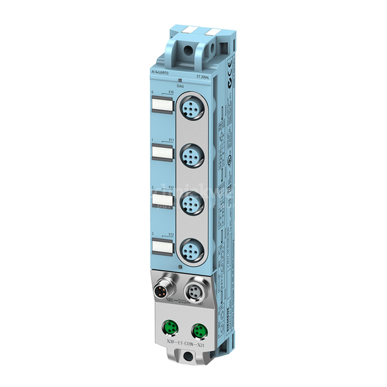
Product overview Properties Article number 6ES7144-5KD50-0BA0 View of the module Figure 2-1 View of the analog input module AI 4xRTD/TC 4xM12 Analog input module AI 4xRTD/TC 4xM12 (6ES7144-5KD50-0BA0) Equipment Manual, 08/2020, A5E48753535-AA... - Page 11 Product overview 2.1 Properties Properties The module has the following technical properties: • 4 analog inputs • M12 sockets for connection of sensors • Measurement type can be set for each channel: – Voltage measurement: ±80 mV – Resistance measurement: 0-150 Ohm, 0-300 Ohm (2-/3-/4-wire connection) –...
- Page 12 • M8 sealing cap • M12 sealing cap See also You can find more information on accessories in the Accessories/spare parts section of the ET 200AL distributed I/O system (https://support.industry.siemens.com/cs/ww/en/view/89254965) system manual. Analog input module AI 4xRTD/TC 4xM12 (6ES7144-5KD50-0BA0) Equipment Manual, 08/2020, A5E48753535-AA...
-
Page 13: Operator Controls And Display Elements
Product overview 2.2 Operator controls and display elements Operator controls and display elements The figure below shows the operator control and display elements of the analog input module AI 4xRTD/TC 4xM12. ① DIAG: LED display for the diagnostic status ② X10 to X13: Sockets for the input signal ③... -
Page 14: Wiring
Wiring Terminal and block diagram The figure below shows an example of the pin assignment for voltage measurement and thermocouple measurement. ① Voltage measurement Infeed of the ET-Connection ② Thermocouple measurement Loop-through of the ET-Connection ③ Multiplexer Supply voltage 1L+ (non-switched) ④... - Page 15 Wiring 3.1 Terminal and block diagram The figure below shows an example of the pin assignment for thermal resistance and resistance measurement. ① RTD/R 2-wire connection Infeed of the ET-Connection ② RTD/R 3-wire connection Loop-through of the ET-Connection ③ RTD/R 4-wire connection Supply voltage 1L+ (non-switched) ④...
-
Page 16: Pin Assignment
Wiring 3.2 Pin assignment Pin assignment Note Color coding The sockets for ET-Connection and the power supply of the modules are color-coded. These colors correspond to the colors of the offered cables. Pin assignment of the sockets for analog inputs The tables below show the pin assignments of the four sockets for connection of the analog inputs. - Page 17 Wiring 3.2 Pin assignment Table 3- 3 Pin assignment for analog inputs (RTD/R 3-wire connection) Assignment Front view of the sockets X10 ... X13 - sockets for analog inputs (RTD/R 3-wire connection) Constant current cable Ic +: Connector X10 Constant current cable Ic +: Connector X11 Constant current cable Ic +: Connector X12...
- Page 18 Wiring 3.2 Pin assignment Pin assignment of the sockets for ET-Connection The table below shows the pin assignments of the 2 sockets for the connection of ET-Connection. Table 3- 5 Pin assignment for ET-Connection Assignment Assignment of the Front view of the sockets core color of the X30 socket X31 socket...
- Page 19 Wiring 3.2 Pin assignment The table below shows the pin assignment of the socket for loop-through of the supply voltage. Table 3- 7 Pin assignment of the supply voltage socket Assignment Assignment of the Front view of the core color of the socket X81 socket (POWER output) power cable...
-
Page 20: Parameters/Address Space
Parameters/address space Measurement types and measuring ranges The table below indicates which measuring range is configurable. Table 4- 1 Measurement type and measuring ranges Measurement type Measuring range Temperature coeffi- Resolution cient Deactivated – – – Voltage +/- 80 mV –... -
Page 21: Parameters
Parameters/address space 4.2 Parameters Parameters Parameters of the analog input module AI 4xRTD/TC 4xM12 Specify the module properties with the various parameters in the course of the parameter assignment of the module with STEP 7. The following table lists the configurable parameters. The effective range of the configurable parameters depends on the type of configuration. - Page 22 Parameters/address space 4.2 Parameters Parameter Value range Default Effective range with config- uration software e.g. STEP 7 (TIA Portal) GSD file GSD file PROFINET IO PROFIBUS DP Thermal resistor (2-, 3-, 4-wire connection) • Pt 100 climatic range • Pt 1000 climatic range •...
- Page 23 Parameters/address space 4.2 Parameters Parameter Value range Default Effective range with config- uration software e.g. STEP 7 (TIA Portal) GSD file GSD file PROFINET IO PROFIBUS DP Smoothing None Channel Channel • None • Weak • Medium • Strong Interference fre- 50 Hz (20 ms) Channel Channel...
- Page 24 Parameters/address space 4.2 Parameters Note Unused channels "Deactivate" unused inputs in the parameter assignment to shorten the cycle time of the module. A deactivated input always returns the value 7FFF Value ranges of the hardware interrupts The table below shows the permitted value ranges of the hardware interrupts for the measurement type.
- Page 25 Parameters/address space 4.2 Parameters Measurement Measuring range Low limit High limit Unit type Thermocouple Type B -119.9 2069.9 °C -1199 20699 Decimal -183.9 3276.5 -1839 32765 Decimal 153.3 2343.1 1533 23431 Decimal Type N -269.9 1549.9 °C -2699 15499 Decimal -453.9 2821.9 -4539...
- Page 26 Parameters/address space 4.2 Parameters Measurement Measuring range Low limit High limit Unit type -4539 29515 Decimal 1895.1 18951 Decimal Type U -199.9 849.9 °C -1999 8499 Decimal -327.9 1561.9 -3279 15619 Decimal 73.3 1123.1 11231 Decimal Type C -119.9 2499.9 °C -1199 24999...
-
Page 27: Explanation Of The Parameters
Parameters/address space 4.3 Explanation of the parameters Explanation of the parameters Temperature unit You use this parameter to set the temperature unit with which you want to measure the temperature. Type/range of measurement You use this parameter to set the measurement type or the measuring range for acquiring the measured values. - Page 28 Parameters/address space 4.3 Explanation of the parameters The possible compensation types that can be parameterized via the parameter "reference junction" are set out in the table below. Table 4- 5 Parameterizable compensation types for the "reference junction" parameter Compensation Explanation type Fixed reference Properties...
- Page 29 Parameters/address space 4.3 Explanation of the parameters Compensation Explanation type Properties Internal reference junction With this compensation type, the reference junction temperature is determined with an internal tem- perature sensor that is integrated in the AI 4xRTD/TC 4xM12 electronic module. Note: Take the reaction time to changes of the ambient temperature into account.
- Page 30 Parameters/address space 4.3 Explanation of the parameters Smoothing The purpose of smoothing is to filter out interferences. The greater the smoothing factor, the better the filter effect. This is technically implemented in the form of a digital filter. The smoothing can be set in 4 levels. The smoothing factor k is equal to the number of module cycles.
- Page 31 Parameters/address space 4.3 Explanation of the parameters Diagnostics: Wire break Enabling of the diagnostics if the analog input module has no current flow or the current is too weak for measurement at the correspondingly configured input. Note Wire break diagnostics With analog input channels, wire break diagnostics is not possible for the measurement type voltage ±...
- Page 32 Parameters/address space 4.3 Explanation of the parameters Hardware interrupt high/low limit 1 or 2 Enabling of a hardware interrupt when the high limit 1 or 2 or the low limit 1 or 2 is violated. Requirement: An OB 4x must be assigned to the CPU/device. Additional information on the structure of hardware interrupts is available in the section Interrupts (Page 37).
-
Page 33: Structure Of A Data Record For Dynamic Reference Temperature
Parameters/address space 4.4 Structure of a data record for dynamic reference temperature Structure of a data record for dynamic reference temperature The WRREC instruction is used to transfer the reference junction temperature via data record 192 to data record 195 to the module. The description of the WRREC instruction can be found in the online help from STEP 7. - Page 34 Additional information You can find more information on compensation of the reference junction temperature via data record in the function manual SIMATIC analog value processing (https://support.industry.siemens.com/cs/ww/en/view/67989094). Analog input module AI 4xRTD/TC 4xM12 (6ES7144-5KD50-0BA0) Equipment Manual, 08/2020, A5E48753535-AA...
-
Page 35: Address Space
Parameters/address space 4.5 Address space Address space The figure below shows the assignment of the address space for the AI 4xRTD/TC 4xM12 analog input module with value status (Quality Information, QI). If you are using PROFINET and the value status has been enabled, the addresses for the value status are available. The value status is not available for PROFIBUS. -
Page 36: Interrupts/Diagnostics Alarms
Interrupts/diagnostics alarms Status and error displays LED displays The figure below shows the LED display (status and error displays) of the AI 4xRTD/TC 4xM12 analog input module. ① Diagnostic status (DIAG) (red/green) ② Channel status (0, 1, 2 and 3) (green) Figure 5-1 LED displays... - Page 37 Interrupts/diagnostics alarms 5.1 Status and error displays DIAG LED Table 5- 1 Error display of the DIAG LED DIAG LED Meaning No supply voltage 1L+ • Module parameters not assigned Flashes • Loading firmware (while the firmware update is being performed, all LEDs retain their current status) •...
-
Page 38: Interrupts
Interrupts/diagnostics alarms 5.2 Interrupts Interrupts The AI 4xRTD/TC 4xM12 analog input module supports diagnostic and hardware interrupts. Diagnostic interrupt The table below shows the events for which the analog input module returns a diagnostic interrupt, depending on the parameter assignment. Table 5- 3 Diagnostic interrupts Measure-... - Page 39 Interrupts/diagnostics alarms 5.2 Interrupts The figure below shows the assignment to the bits of the local data double word 8. Figure 5-2 Start information of the organization block Structure of the additional interrupt information Table 5- 4 Structure of the additional interrupt information Data block name Contents Comment...
-
Page 40: Diagnostics Alarms
Interrupts/diagnostics alarms 5.3 Diagnostics alarms Diagnostics alarms A diagnostics alarm is output for each diagnostics event. The DIAG LED flashes red on the analog output module. The diagnostics alarms are listed in the diagnostics buffer of the CPU. You can evaluate the error codes with the user program. The following tables set out the diagnostics alarms for the set measuring range. -
Page 41: Technical Specifications
Technical specifications of the AI 4xRTD/TC 4xM12 analog input module The following table shows the technical specifications as of 08/2020. You will find a data sheet including daily updated technical specifications on the Internet (https://support.industry.siemens.com/cs/ww/en/pv/6ES7144-5KD50-0BA0/td?dl=en). Article number 6ES7144-5KD50-0BA0 General information... - Page 42 Technical specifications 6.1 Technical specifications Article number 6ES7144-5KD50-0BA0 Analog inputs Number of analog inputs • For voltage measurement • For resistance/resistance thermometer measurement • For thermocouple measurement permissible input voltage for voltage input 15 V (destruction limit), max. Constant measurement current for resistance- 230 ...
- Page 43 Technical specifications 6.1 Technical specifications Article number 6ES7144-5KD50-0BA0 Input ranges (rated values), resistance ther- mometer Yes; Standard/climate • Ni 100 10 MΩ Input resistance (Ni 100) – Yes; Standard/climate • Ni 1000 10 MΩ Input resistance (Ni 1000) – Yes; Standard/climate •...
- Page 44 Technical specifications 6.1 Technical specifications Article number 6ES7144-5KD50-0BA0 60 / 50 / 16.7 • Interference voltage suppression for inter- ference frequency f1 in Hz Smoothing of measured values • parameterizable Yes; 1x cycle time • Step: None Yes; 4x cycle time •...
- Page 45 Technical specifications 6.1 Technical specifications Article number 6ES7144-5KD50-0BA0 Interference voltage suppression for f = n x (f1 +/- 0.5 %), f1 = interference frequency 40 dB • Series mode interference (peak value of interference < rated value of input range), min.
- Page 46 Technical specifications 6.1 Technical specifications Article number 6ES7144-5KD50-0BA0 Dimensions Width 30 mm Height 159 mm Depth 40 mm Weights Weight, approx. 168 g Analog input module AI 4xRTD/TC 4xM12 (6ES7144-5KD50-0BA0) Equipment Manual, 08/2020, A5E48753535-AA...
-
Page 47: Dimension Drawing
Dimension drawing Dimension drawing The figure below shows the dimension drawing of the AI 4xRTD/TC 4xM12 analog input module in the front and side view. Figure A-1 Dimension drawing Analog input module AI 4xRTD/TC 4xM12 (6ES7144-5KD50-0BA0) Equipment Manual, 08/2020, A5E48753535-AA... -
Page 48: Representation Of Analog Values
Representation of analog values Representation of analog values in voltage measuring range The table below lists the decimal and hexadecimal values (codes) of the voltage measuring range. Table B- 1 Voltage measuring range ± 80 mV Values Voltage measuring range Range Dec. -
Page 49: Representation Of Analog Values For Resistance-Based Sensors
Representation of analog values B.2 Representation of analog values for resistance-based sensors Representation of analog values for resistance-based sensors Resistance-based sensor The following tables list the decimal and hexadecimal values (codes) of the resistance-based sensor. Table B- 2 Resistance-based sensor of 150 Ω and 300 Ω Values Resistance-based sensor range Range... -
Page 50: Representation Of Analog Values For Thermal Resistors
Representation of analog values B.3 Representation of analog values for thermal resistors Representation of analog values for thermal resistors The tables below list the decimal and hexadecimal values (codes) of the thermal resistors. Table B- 3 Thermal resistor Pt 100, Pt 1000 Standard Pt x00 Values Pt x00... - Page 51 Representation of analog values B.3 Representation of analog values for thermal resistors Table B- 5 Thermal resistor Ni 100, Ni 1000 Standard Ni x00 Values Ni x00 Values Ni x00 Values Range Standard in Standard in Standard in Dec. Hex. Dec.
-
Page 52: Representation Of Analog Values For Thermocouples
Representation of analog values B.4 Representation of analog values for thermocouples Representation of analog values for thermocouples The tables below list the decimal and hexadecimal values (codes) of the thermocouples. Table B- 7 Thermocouple type B Type B in Values Type B Values Type B... - Page 53 Representation of analog values B.4 Representation of analog values for thermocouples Table B- 9 Thermocouple type E Type E Values Type E Values Type E Values Range in °C in °F in K Dec. Hex. Dec. Hex. Dec. Hex. > 1200.0 32767 7FFF >...
- Page 54 Representation of analog values B.4 Representation of analog values for thermocouples Table B- 12 Thermocouple type L Type L Values Type L Values Type L Values Range in °C in °F in K Dec. Hex. Dec. Hex. Dec. Hex. > 1150.0 32767 7FFF >...
- Page 55 Representation of analog values B.4 Representation of analog values for thermocouples Table B- 15 Thermocouple type T Type T Values Type T Values Type T Values Range in °C in °F in K Dec. Hex. Dec. Hex. Dec. Hex. > 540.0 32767 7FFF >...