Table of Contents
Advertisement
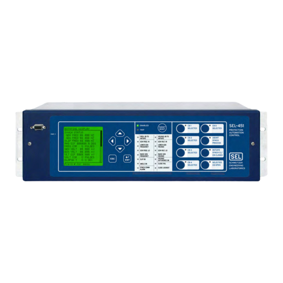
SEL-451-5-Based
Autosynchronizer
A custom-engineered solution for safe,
secure autosynchronization of generation
Major Features and Benefits
SEL combines engineering services with the field-proven SEL-451-5 Relay for Advanced Autosynchronizing
(A25A) systems with the features and flexibility that customers have come to expect from SEL products and
systems. The SEL-451-5-based A25A is sold as a configuration and documentation disc. The user separately
purchases the SEL-451-5 Protection, Automation, and Bay Control System Relay per the Model Option Table
requirements detailed in this data sheet. Alternatively, the user can contact SEL Engineering Services to
obtain a fully engineered customized solution. Please refer to the SEL-451-5 data sheet for complete informa-
tion on the standard features available in this powerful device.
The pre-engineered A25A includes the following features:
➤
Generator Frequency and Voltage Matching Control. Pulse governor and exciter reference points
to bring a generator into synchronism acceptance criteria. Pulse interval and pulse width parameters
are configurable for multiple synchronization situations. The control supports either fixed or propor-
tional pulse width control characteristics.
➤
Breaker Close Delay Compensation. Issue a close signal in advance of zero degrees phase coinci-
dence so that the main contacts make as the generator phase angle difference reaches zero degrees.
➤
Generator Frequency Greater Than Bus Frequency (GF > BF) (Antimotoring) Control. Apply in
situations with prime movers with extremely sensitive reverse power protection. The system requires
generator frequency greater than bus frequency to cause initial power flow to be out of the generator to
prevent trip of reverse power protection upon initial synchronization of the generator.
➤
Dead-Scope Control. Generate a frequency raise pulse to prevent a near-zero slip-rate condition in
which two systems move very slowly relative to one another and take a long time to rotate into phase.
➤
Generator Voltage Greater Than Bus Voltage (GV > BV) Control. Apply in situations where it is
necessary to prevent the generator from absorbing VARs from the system and pulling down the system
voltage on initial synchronization.
Schweitzer Engineering Laboratories, Inc.
onto the power system
SEL-451-5-Based Autosynchronizer Data Sheet
Advertisement
Table of Contents

Related Manuals for Sel SEL-451-5


Summary of Contents for Sel SEL-451-5
- Page 1 SEL combines engineering services with the field-proven SEL-451-5 Relay for Advanced Autosynchronizing (A25A) systems with the features and flexibility that customers have come to expect from SEL products and systems. The SEL-451-5-based A25A is sold as a configuration and documentation disc. The user separately purchases the SEL-451-5 Protection, Automation, and Bay Control System Relay per the Model Option Table requirements detailed in this data sheet.
- Page 2 This feature is ideal for cogeneration applications where the cogenerator can operate with critical load islanded from the grid and needs to be synchronized back to the grid after a disturbance. Many other configurations are possible with customization. See the SEL-451-5 Data Sheet for more information on M IRRORED ➤...
-
Page 3: Ordering Information
SEL-5030 Software Settings Interface. Easily set the autosyn- ERATOR chronizer by using the provided settings template, which hides all of the settings for unused features of the SEL-451-5 Relay and organizes all the user settings required to configure autosynchronizer fea- tures. ➤... - Page 4 Note 4: Select Option 1X if standard I/O is required. Select Option 27 if the second I/O board is required. See Table 3 for additional features provided with the second I/O board. Figure 2 Rear Panel of SEL-451-5 With Standard I/O (a) and With Optional Second I/O Board (b) SEL-451-5-Based Autosynchronizer Data Sheet...
-
Page 5: Control Functions
The correction dead band is fixed with a 20 percent mar- the frequency of the bus. When isolated from the system, gin inside the slip allowed synchronism acceptance set- the governor control operates in isosynchronous (fre- ting. Schweitzer Engineering Laboratories, Inc. SEL-451-5-Based Autosynchronizer Data Sheet... - Page 6 Figure 5 shows the proportional pulse control character- ➤ Pulse interval (seconds) istic when the GV > BV feature is enabled. Figure 6 ➤ Enable/disable GV > BV shows the control characteristic when the GV > BV fea- SEL-451-5-Based Autosynchronizer Data Sheet Schweitzer Engineering Laboratories, Inc.
- Page 7 80% Voltage Difference Allowed Gen. Voltage < Bus Voltage Gen. Voltage > Bus Voltage PU Volts Proportional Correction Pulse Range, ±400% Voltage Difference Allowed Figure 6 Proportional Voltage Correction Pulse Characteristic With GV>BV Disabled Schweitzer Engineering Laboratories, Inc. SEL-451-5-Based Autosynchronizer Data Sheet...
- Page 8 Thus, it cannot discern between a dead bus and a blown VT fuse. To prevent an out-of-synchronization Figure 7 Operator Close Permissive Window close via the dead-bus permissive path when a VT fuse SEL-451-5-Based Autosynchronizer Data Sheet Schweitzer Engineering Laboratories, Inc.
- Page 9 Antipump (One Close Attempt Allowed) Logic Once an automatic close has been initiated, a latch is set that blocks any additional close attempts. The latch is automatically reset when the breaker is deselected. Schweitzer Engineering Laboratories, Inc. SEL-451-5-Based Autosynchronizer Data Sheet...
-
Page 10: Typical Connections
Lower outputs, the terminal numbers change from starting with “A” to starting with “B” and the output contact numbers change from 1xx series to 2xx series. The optional high-current interrupting contacts are polarity-sensitive, with the lower number terminal as the “+” terminal. Figure 8 A25A Typical Connection Diagram SEL-451-5-Based Autosynchronizer Data Sheet Schweitzer Engineering Laboratories, Inc. - Page 11 IN208 Operator Close Permissive OUT209 Voltage OK to initiate OUT210 Frequency OK to initiate OUT211 Slip OK OUT212 Voltage OK OUT213 Angle OK OUT214 Close Fail OUT215 Close Lockout High-current interrupting contact. Schweitzer Engineering Laboratories, Inc. SEL-451-5-Based Autosynchronizer Data Sheet...
-
Page 12: User Interface
Table 4 shows a complete listing of input and output functions for the optional Remote I/O module connected via M . See the SEL-451-5 Data Sheet for more information on M RORED IRRORED Table 4 I/O for M When Optional RIO Device Used... - Page 13 Figure 14. The template works inside the QuickSet settings environment. This template orga- nizes the settings for the autosynchronizer functionality ROTATING DISPLAY and hides most SEL-451-5 settings unused in the auto- FREQ MATCHING DETAIL FREQ COR XXX PULSES synchronizer control application.
-
Page 14: Application Examples
G1, G2, and G3. available single-phase inputs. You can then add optional I/O boards to the SEL-451-5 to control as many genera- tors and generator breakers as necessary via separate out- put contacts. This functionality, combined with the... - Page 15 Device 67-SEP, located at the critical load bus, includes SEL-451-5 relay. Device 67-SEP on CB TIE receives the voltage and frequency elements as well as directional advance angle-compensated autosynchronization close overcurrent elements that separate the critical load bus command via M Channel A.
- Page 16 Guideform Specification The SEL Advanced Autosynchronization System, based on the SEL-451-5 microprocessor-based relay, shall provide control, protection, monitoring, and automation. Relay self-checking functions shall be included. Specific requirements are as follows: ➤ Frequency Matching. The system shall provide rate-of-change of voltage and rate-of-change of...
- Page 17 Ethernet ports of the relay. The relay shall provide for all material and workmanship defects. In addi- the capability to produce as many as five PMU data tion, the warranty shall cover accidental customer- configurations. induced damage. Schweitzer Engineering Laboratories, Inc. SEL-451-5-Based Autosynchronizer Data Sheet...
-
Page 18: Specifications
Specifications Please refer to the product data sheet for the SEL-451-5 Protection, Automation, and Control System for front-panel and rear-panel diagrams, relay dimensions, and additional specifications. This data sheet contains information on specific features and functions provided in the pre-engineered advanced autosynchronizer system. -
Page 19: Factory Assistance
Factory Assistance We appreciate your interest in SEL products and services. If you have any questions or comments, please contact us at: Engineering Services Division Schweitzer Engineering Laboratories, Inc. 2350 NE Hopkins Court Pullman, WA 99163-5603 U.S.A. Tel: +1.509.332.1890 Fax: +1.509.332.7990 Internet: www.selinc.com... - Page 20 2350 NE Hopkins Court • Pullman, WA 99163-5603 USA trademark of their respective holders. No SEL trademarks may be used without written Phone: +1.509.332.1890 • Fax: +1.509.332.7990 permission. SEL products appearing in this document may be covered by U.S. and Foreign Internet: www.selinc.com • E-mail: info@selinc.com patents.
Need help?
Do you have a question about the SEL-451-5 and is the answer not in the manual?
Questions and answers