Table of Contents
Advertisement
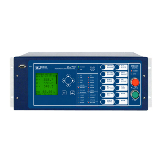
SEL-451-5 Protection, Automation,
and Bay Control System
Key Features and Benefits
The SEL-451-5 Protection, Automation, and Bay Con-
trol System integrates bay control for breakers and dis-
connect switches with full automation and protection in
one device.
➤
Protection. Customize distribution protection with
multiple instantaneous and time-overcurrent
OGIC ®
elements with SEL
Choice Ground Directional Element
optimizes directional element performance and
eliminates the need for many directional settings.
Provide comprehensive protection for two breakers
with one relay.
➤
Commissioning. Rapidly commission your Bay
Control with preconfigured bay arrangements.
Choose among different bus configurations,
including single- and dual-busbar, transfer bus, tie
breaker, breaker-and-a-half, ring-bus, double-
bus/double-breaker, and source transfer
configurations. These bus arrangements allow easy
status and control of as many as ten disconnect
switches and two breakers. Additional user-
selectable bay types are available via
SEL
QuickSet
AC
ERATOR
that can be downloaded at selinc.com.
➤
Automation. Take advantage of enhanced
automation features that include 32 programmable
elements for local control, remote control,
protection latching, and automation latching. Local
metering on the large format front-panel LCD
Schweitzer Engineering Laboratories, Inc.
control equations. Best
®
logic
®
SEL-5030 Software
eliminates the need for separate panel meters.
Serial and Ethernet links efficiently transmit key
information, including metering data, protection
element and control input/output (I/O) status, IEEE
C37.118 Synchrophasors, IEC 61850 Edition 2
GOOSE messages, Sequential Events Recorder
(SER) reports, breaker monitor, relay summary
event reports, and time synchronization. Apply
expanded SEL
control equations with math
OGIC
and comparison functions in control applications.
Incorporate as many as 1000 lines of automation
logic to speed and improve control actions.
➤
Software-Invertible Polarities. Invert individual
or grouped CT and PT polarities to account for
field wiring or zones of protection changes. CEV
files and all metering and protection logic use the
inverted polarities, whereas COMTRADE event
reports do not use inverted polarities but rather
record signals as applied to the relay.
➤
Synchrophasors. Make informed load dispatch
decisions based on actual real-time phasor
measurements from SEL-451 Relays across your
power system. Record streaming synchrophasor
data from SEL-451 Relays for system-wide
disturbance recording. Control the power system
using local and remote synchrophasor data.
SEL-451 Data Sheet
Advertisement
Table of Contents

Related Manuals for Sel SEL-451-5


Summary of Contents for Sel SEL-451-5
- Page 1 SEL-451-5 Protection, Automation, and Bay Control System Key Features and Benefits The SEL-451-5 Protection, Automation, and Bay Con- eliminates the need for separate panel meters. trol System integrates bay control for breakers and dis- Serial and Ethernet links efficiently transmit key...
- Page 2 IRRORED monitor internal element conditions between bays faster. within a station, or between stations, using SEL ➤ IEC 60255-Compliant Thermal Model. Use fiber-optic transceivers. Send digital, analog, and the relay to provide a configurable thermal model...
- Page 3 Ethernet* EIA-232 High-Accuracy Metering Synchrophasors Station Battery Monitor Sequential Events Recorder Software-Invertible Polarities IEC 60255-Compliant Thermal Model TiDL Time-Domain Link Remote Data Acquisition Copper or Fiber-Optic * Optional Feature Figure 1 Functional Diagram Schweitzer Engineering Laboratories, Inc. SEL-451 Data Sheet...
-
Page 4: Product Overview
The SEL-451 includes a number of directional elements for supervision of overcurrent elements. The negative- All signal processing uses the software-inverted polari-... -
Page 5: Communications-Assisted Tripping Schemes
Use communications to improve tripping time for better Even in cases with delayed current zero in the secondary customer service. The SEL-451 is the ideal relay for use of the CT caused by trapped flux, high-speed detection in pilot-based tripping schemes. Enhanced M IRRORED of circuit breaker opening is achieved. -
Page 6: Six Independent Settings Groups Increase Operation Flexibility
CT inputs ➤ Eight independent inputs, 13 standard Form A and before connecting these inputs to the relay. The SEL-451 two standard Form C contact outputs. can accept separate inputs from two separate CTs and ➤... -
Page 7: Bay Control
Flexible Applications ing order based on system conditions. Bus 1 Two-Breaker Control The SEL-451 contains analog voltage inputs for multiple sources and control inputs to indicate both breaker and disconnect position, as well as the logic required to pro- 52-1 vide full control for two breakers. -
Page 8: Circuit Breaker Operations From The Front Panel
BUSNAM1 BUSNAM2 ing or closing switches or breakers. The SEL-451 will not only prevent the operator from making an incorrect control decision, but can notify and/or alarm when an incorrect operation is initiated. -
Page 9: Rack-Type Breakers Mosaics
Set interface supports Server 2008, Windows 7 and Windows 8 operating systems, and can be used to open The SEL-451 has the ability to designate a disconnect as COMTRADE files from SEL and other products. Con- having control functionality or being status-only. When a... -
Page 10: Quickset Bay Control Settings Interface
This ➤ Lock settings to match your standard for protection, action automatically displays all the settings for the I/O assignment, communications, and SEL OGIC device selected. This method provides an easy way of control equations. -
Page 11: Status And Trip Target Leds
LEDs and operator control pushbuttons and LEDs. The blank slide-in label set is included with the SEL-451. Label sets can be printed from a laser printer using templates supplied with the relay or hand labeled on supplied blank labels. -
Page 12: Advanced Display Points
SF6 ALARM Figure 15 Sample Display Points Screen Alarm Points You can display messages on the SEL-451 front-panel LCD that indicate alarm conditions in the power system. The relay uses alarm points to place these messages on Figure 17 Operator Controls (Auxiliary Trip/Close Model) the LCD. -
Page 13: Monitoring And Metering
A single IRIG-B time-code input synchronizes the send an Event Summary in ASCII text to one or more SEL-451 time to within 1 ms of the time-source input. relay communications ports each time an event report is A convenient source for this time code is the SEL-2032 triggered. -
Page 14: Sntp Time Synchronization
Substation Battery Monitor for DC SEL-487B Quality Assurance Figure 19 Example PTP Network The SEL-451 measures and reports the substation battery voltage for two battery systems. Two sets of programma- SNTP Time Synchronization ble threshold comparators and associated logic provide alarm and control of two separate batteries and chargers. -
Page 15: Breaker Monitor Feature Allows For Wear-Based Breaker Maintenance Scheduling
The SEL-451 supports remote data acquisition through connected topology. This limits the number of settings use of an SEL Axion with a technology known as TiDL. and makes converting an existing system to TiDL easy. The Axion provides remote analog and digital data over Figure 22 show sample TiDL topologies. -
Page 16: Flexible Control Logic And Integration Features
Program latch set and latch reset conditions with control equations. Set or reset the latch control OGIC The SEL-451 control logic can be used to perform the points via control inputs, remote control points, local following: control points, or any programmable logic condition. The latch control points retain states when the relay loses power. -
Page 17: Sel Ogic Control Equations With Expanded Capabilities And Aliases
I/O, targets, SER, relay summary event reports, and settings groups. IEEE C37.118 Phasor measurement protocol. IEC 61850 Edition 2 Ethernet-based international standard for interoperability between intelligent devices in a substation. Table 5 SEL Control Equation Operators OGIC Operator Type Operators... - Page 18 M communications capabilities for high- IRRORED (Hot Line/Dead Bus) speed communications-assisted schemes applied to three-ter- minal transmission lines. Communication The SEL-451 offers the following serial communication 2nd Reclose features. (Hot Bus/Dead Line) ➤ Four independent EIA-232 serial ports. ➤...
-
Page 19: Network Connection And Integration
Control Access Figure 25 Network Connection and Integration Connect the SEL-451 to Local Area Networks (LANs) munications sessions. Use Telnet to access relay settings, by using the optional Ethernet card. The integrated and metering and event reports remotely using the ASCII Ethernet card supports both copper and/or fiber connec- interface. -
Page 20: Parallel Redundancy Protocol (Prp)
IEDs from different manufacturers for ➤ IEC 61850 Edition 2 Data Server. The SEL-451 is monitoring and control of the substation. Reduce wiring equipped with embedded IEC 61850 Ethernet among various manufacturers’ devices and simplify protocol that provides data according to pre- operating logic with IEC 61850. -
Page 21: Mms File Services
ERATOR ® This service of IEC 61850 MMS provides support for Architect SEL-5032 Software to ERATOR file transfers completely within an MMS session. All manage the logical node data for all IEC 68150 devices relay files that can be transferred via FTP can also be on the network. -
Page 22: Diagrams And Dimensions
Diagrams and Dimensions 3U Front Panel, Rack-Mount Option With Optional Bay Control Overlay 4U Front Panel, Panel-Mount Option 5U Front Panel, Panel-Mount Option With Auxiliary Trip/Close Pushbuttons Figure 27 Typical SEL-451 Front-Panel Diagrams SEL-451 Data Sheet Schweitzer Engineering Laboratories, Inc. - Page 23 3U Rear Panel, Main Board 4U Rear Panel, Main Board, Connectorized ® Option, INT5 I/O Board 4U Rear Panel, Main Board, INT1 I/O Board, LEA Voltage Inputs Figure 28 Typical 3U and 4U SEL-451 Rear-Panel Diagrams Schweitzer Engineering Laboratories, Inc. SEL-451 Data Sheet...
- Page 24 5U Rear Panel, Main Board, With Two INT4 I/O Boards Figure 29 Typical 5U SEL-451 Rear-Panel Diagram Figure 30 Rear Panel With EtherCAT Board SEL-451 Data Sheet Schweitzer Engineering Laboratories, Inc.
- Page 25 (Horizontal Mounting Shown; Dimensions Also Apply to Vertical Mounting) Figure 31 SEL-451 Dimensions for Rack- and Panel-Mount Models Schweitzer Engineering Laboratories, Inc. SEL-451 Data Sheet...
-
Page 26: Specifications
1s Rating: 50 A Ten-Second Thermal Rating: 600 Vac MOV Protection (Maximum Voltage): 250 Vac/ 330 Vdc 0.1 VA @ 125 V Burden: 6 ms, resistive load Pickup/Dropout Time: Update Rate: 1/8 cycle SEL-451 Data Sheet Schweitzer Engineering Laboratories, Inc. - Page 27 Resistive DC or AC Outputs With Arc Suppression Disabled 24 Vac: Pickup 16.4–30.0 Vac rms Make: 30 A per IEEE C37.90 2005 48 Vac: Pickup 32.8–60.0 Vac rms; Carry: 6 A continuous carry Dropout <20.3 Vac rms Schweitzer Engineering Laboratories, Inc. SEL-451 Data Sheet...
- Page 28 IEC 61000 8:2009 Logic Low Threshold: 1000 A/m for 3 s 50 or > 1 k Input Impedance: 100 A/m for 1 min IEC 61000 9:2001 Dielectric Test Voltage: 0.5 kVac 1000 A/m SEL-451 Data Sheet Schweitzer Engineering Laboratories, Inc.
-
Page 29: Reporting Functions
0.25–24 seconds (based on LER and current between 2 and 30 multiples of SRATE settings) pickup) Volatile Memory: 3 s of back-to-back event reports sampled Reset: 1 power cycle or Electromechanical Reset at 8 kHz Emulation time Schweitzer Engineering Laboratories, Inc. SEL-451 Data Sheet... - Page 30 Pickup Accuracy: 1 A nominal ±5% ±0.02 A Accuracy: ±2°C 5 A nominal ±5% ±0.10 A As long as 500 m Fiber-Optic Cable to SEL 2600 Series RTD Module Time-Delay Accuracy: ±0.1% plus ±0.125 cycle Breaker Failure Instantaneous Overcurrent Ground Directional Elements Setting Range Neg.-Seq.
-
Page 31: Metering Accuracy
64 (any Relay Word bit) 300 V Maximum Inputs Synchrophasor Protocol: IEEE C37.118, Phase and Phase-to-Phase ±2.5% ±1 V (5–33.5 V) SEL Fast Message (Legacy) Voltage Magnitude: ±0.1% (33.5–300 V) Synchrophasor Data Rate: As many as 60 messages per second Phase and Phase-to-Phase ±1.0°... - Page 32 All brand or product names appearing in this document are the trademark or registered trademark of their respective holders. No SEL trademarks may be used without written Tel: +1.509.332.1890 • Fax: +1.509.332.7990 permission. SEL products appearing in this document may be covered by U.S. and Foreign selinc.com • info@selinc.com patents.
Need help?
Do you have a question about the SEL-451-5 and is the answer not in the manual?
Questions and answers