
Subscribe to Our Youtube Channel
Related Manuals for Azkoyen HOPPER U-II


Summary of Contents for Azkoyen HOPPER U-II
- Page 1 HOPPER U-II AZKOYEN Medios de Pago, S.A Tel.: +34 948 709 709 Avda. San Silvestre, s/n Fax: +34 948 709 709 31350 Peralta (Navarra) Spain www.azkoyen.com...
-
Page 2: Table Of Contents
POWER SUPPLY. 3.2. CURRENT DRAW. 3.3. DIMENSIONS. 3.4. ELECTRICAL DIAGRAMS AND PIN OUT. 3.4.1. - Electrical diagram of the Hopper U-II ccTalk. 3.4.2. - Electrical diagram of the Hopper U-II parallel. DESCRIPTION OF COMPONENTS 4.1. COIN BAY 4.2. MOVING FLAP. - Page 3 4.13. ACCESSORIES. 4.13.1. Mechanical supplement to increase the capacity of the hopper. 4.13.2. Overflow. 4.13.3. Electromechanical scales. TOOLS. 5.1. TL20 AND HEUS. WORKING CONDITIONS AND NORMS. CLEANING AND MAINTENANCE VERSION 2.0 06 - 2011...
- Page 4 Figure 12. Parallel Control board ............... 18 Figure 13. Pin out Hopper U-II parallel standard........19 Figure 14. Pin out Hopper U-II parallel with empty detection....19 Figure 15. Pin out Hopper U-II parallel with full and empty detection.
-
Page 5: Introduction
Hopper U-II parallel Hopper U-II parallel plus The rotating Hopper U-II is a result of the redesigning process of the traditional Hopper U, obtaining an optimised version of the hopper. This product is 100% compatible with the previous Hopper U model. -
Page 6: Capacity Of The Hopper U-Ii
2.2. RANGE OF COINS. The multicoin extraction system of the hopper U-II, guaranties the payout of coins whose dimensions are between 1.2 and 3.5 mm thick, and 12 to 32 mm in ø. Consult section “... -
Page 7: Detection Of Full And Empty
“163 Test Hopper” (See details in the manual “Protocol ccTalk Hopper U-II”) It is possible to transform a standard Hopper U-II into a Hopper U-II plus with a kit. Once the kit is installed, it is only necessary to change the position of dipswitch 7 (to ON) so that the standard U-II standard works as a Hopper U-II plus. -
Page 8: Hopper U-Ii Plus Cctalk
(see details in the manual “Protocol parallel Hopper U-II”). It is possible to transform a standard Hopper U-II into a Hopper U-II plus with a kit. Once the kit is installed, it is only necessary to change the position of dipswitch 7 ¡Error! No se encuentra el origen de la referencia. -
Page 9: Protocols
Two hoppers can be configured in line with one another to maximise the use of space. Figure 2. Configuration of the Hopper U-II in line. Figure 3 indicates the positions that the bases of the Hopper U-II should be placed to achieve optimum performance of the two hoppers in line. -
Page 10: Anti-Jam And Anti-Span Systems
Figure 3. Position of the bases of two Hoppers U-II in line. 2.8. ANTI-JAM AND ANTI-SPAN SYSTEMS Jam. The hopper has a current draw detector that, when there is a coin jam, reverses the spin direction of the disk motor for 1.5 seconds to free the jammed coins. -
Page 11: Technical Characteristics
450 mA ± 20% Table 1. Current draw. 3.3. DIMENSIONS. Length Bowl (mm) Small 119.75 Medium Intermediate 190.3 Large 229.3 Tolerance ±1mm Length Bowl (mm) Medium 192.77 Large 229.3 Tolerance ±1mm Figure 4. Dimensions Hopper U-II VERSION 2.0 06 - 2011... -
Page 12: Electrical Diagrams And Pin Out
ELECTRICAL DIAGRAMS AND PIN OUT. 3.4.1. - Electrical diagram of the Hopper U-II ccTalk. The following diagram shows the ccTalk driver included in the Hopper U-II. Figure 5. Diagram Hopper U-II ccTalk. 3.4.2. - Electrical diagram of the Hopper U-II parallel. -
Page 13: Description Of Components
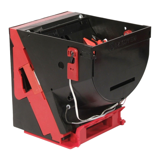
DESCRIPTION OF COMPONENTS Figure 7. Components of the Hopper U-II. 4.1. COIN BAY The coin bay is where the Hopper U stores the coins and where they are extracted from when ordered to do so by the machine. Its design allows the storage of the maximum number of coins in the minimum space, taking into account that even the last coin can be extracted. -
Page 14: Moving Flap
Figure 8. Types of flaps 4.3. COIN LEVEL DETECTORS. The Hopper U-II has full and empty detection sensors. Empty detection. Empty detection is carried out by a photocell (photodiode and phototransistor) that is located in the holes at the bottom of the coin bay. -
Page 15: Blade
Short blade 1.7mm – 3.2mm 12mm – 20mm Modified short blade 1.2mm – 1.7mm 12mm – 20mm * To use the hopper with thinner coins please contact the Aftersales Dept. of Azkoyen. Table 3. Coin dimensions. VERSION 2.0 06 - 2011... -
Page 16: Trigger
In the coin extraction process this device compresses the trigger spring and at a certain point it shoots the coin out of the hopper. The Hopper U-II has only one type of trigger, whereas previous models had two. It is made of plastic. - Page 17 This connector is not operative in the hoppers U-II for Italy. Switches The configuration of the address of the Hopper U-II, as with other functions, is done with the dip switches, 8 switches located on the board which is accessible from the underside of the hopper as shown in the illustration.
- Page 18 Table 6. Addresses for switch combinations. Switch 5 is not used. Switch 6 is used to select the address of the hopper U-II; the address can be selected by using the switches of by the address saved in the memory of the hopper (which can be modified using ccTalk commands).
-
Page 19: Parallel Control Board. Jumpers And Connectors
Figure 12. Parallel Control board Connector for communication with the machine (Parallel protocol). The Hopper U-II uses a connector of 10 pins (2x5) of 2.5mm, series Molex 8624 or similar, for communication with the machine. The pin out of this connector depends on the function of the Hopper: VERSION 2.0... -
Page 20: Figura 16. Logic & Working Mode Configuration
Error Coin Empty Figure 15. Pin out Hopper U-II parallel with full and empty detection. Connector for configuration of the Parallel logic & working Mode. Using connector 6 in figure 16 you can configure the logic, related to the signal levels and the working mode for the Hopper UII Figura 16. -
Page 21: Figura 17. Position Of The Switches
Connector for communication with Azkoyen tools. This connector is used to carry out communication with the Azkoyen tools. (See TL20 AND HEUS. chapter “ ). It is a 6-pin connector with the following pin out: Function Figura 17. Position of the switches VERSION 2.0... -
Page 22: Coin Extractor Disk
4.7. COIN EXTRACTOR DISK The disk picks up the coins in the coin bay and carries them to a position to be ejected from the hopper. The cogs on the outside of the disk mesh with the reduction gear, which makes it spin. It has ridges to hold the coins and drag from the bottom of the coin bay to top where they are ejected by the trigger. -
Page 23: Disk Coin Extractor Motor
DISK COIN EXTRACTOR MOTOR. This element spins the disk for the extraction of coins from the coin bay. The Hopper U-II uses a motor of 12 V that be powered from 12V to 24V ( 10 %). Its electrical characteristics are:... -
Page 24: Disk Support
4.11. DISK SUPPORT The disk support assembly holds the coin extraction components that make up the extraction system and the control board. It has been designed so that the fixture of all these elements is quick and simple, and incorporated the reduction gear for transmitting movement to the disk and the extraction trigger that ejects the coins from the hopper. -
Page 25: Figura 22. Extensions
4.13. ACCESSORIES. 4.13.1. Mechanical supplement to increase the capacity of the hopper. This element is an accessory of the hopper that increases its capacity. There are different models and sizes for each of the different types of hopper. Capacity for coins from Ø 24 mm and 2.8 mm thick Hopper Capacity of the Capacity of... -
Page 26: Figura 23. Overflow
Figura 23. Overflow. 4.13.3. Electromechanical scales. A detection system to detect if the Hopper U-II is full that is based on the weight control of the hopper with coins. When the weight of the coins in the coin bay goes above a set weight, which is adjustable with a screw, a micro switch is activated. -
Page 27: Figura 25. Tl20
The operation of these devices can be summed up in the following points: The user should upload the firmware of the Hopper U-II for updating from the PC to the TL20, using the HEUS software. This software can be obtained from Azkoyen from the website or via email. - Page 28 Power the hopper with a transformer that meets the EN-60742 Norm and provides a maximum of 42.5 Vac without load. Install the hopper U-II series with a maximum inclination of +/- 3ºon all axes. Temperatures: ...
-
Page 29: Figura 26. Cleaning Of The Hopper U-Ii
- It is recommended to clean the coin exit area where the optic sensors are more frequently. This can be done with cotton wool bud dipped in alcohol. Figura 26. Cleaning of the Hopper U-II WARNING: Never use products that contain benzene hydrocarbons. These products severely degenerate the plastic parts producing irreparable damage.
Need help?
Do you have a question about the HOPPER U-II and is the answer not in the manual?
Questions and answers