Huawei PTN Series Quick Installation Manual
Transport platform
Hide thumbs
Also See for PTN Series:
- Quick installation manual (45 pages) ,
- Quick installation manual (21 pages)

Related Manuals for Huawei PTN Series


Summary of Contents for Huawei PTN Series
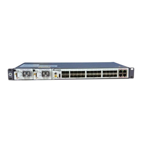
- Page 1 OptiX PTN 910E-F Packet Transport Platform of PTN Series Quick Installation Guide Issue: 04 Date: 2020-03-31 HUAWEI TECHNOLOGIES CO., LTD.
- Page 2 Notice The purchased products, services and features are stipulated by the contract made between Huawei and the customer. All or part of the products, services and features described in this document may not be within the purchase scope or the usage scope. Unless otherwise specified in the contract, all statements, information, and recommendations in this document are provided "AS IS"...
-
Page 3: Installation Precautions
Using the outdoor cabinet IMB network box can moderately improve the device operating environment. If you need to use an outdoor cabinet other than the IMB network box for the PTN 910E-F, contact Huawei to determine whether the outdoor... - Page 4 OptiX PTN 910E-F Appearance ESD wrist strap interface Power supply interface ETH/OAM External clock interface FE/GE optical interface XGE optical interface XGE/GE/FE optical Boolean interface interface ( These interfaces cannot be switched to work at the rate of 10 Gbit/s ) Time interface Equipotential bonding point NOTE...
-
Page 5: Installing The Chassis
Installing the Chassis Scenario 1: Installing the Chassis in a 19-Inch Rack Tightening the floating nut Installing the chassis in the rack Floating nut Align mounting ears with mounting holes of floating nuts and screw the chassis. Reserve at least 1 U vertical space above and below the chassis for heat dissipation. - Page 6 Scenario 2: Installing the Chassis in an ETSI Rack Tightening the floating nut Installing the rack-mounting ear Floating nut Rack- mounting ear: Floating nut hook ( can be replaced using a flat-head screwdriver. ) When tightening floating nuts, keep a distance of at least 50 mm on both the left and right sides of the PTN 910E- M6 combination screws with spring and flat washers F for proper ventilation.
-
Page 7: Installing Cables
Installing Cables Common Cables PGND cable AC power cable DC power cable Fiber Shielded network cable E1 cable ( 120-ohm ) E1 cable ( 75-ohm ) Installing the Power Cable Connecting the AC power cable Connecting the DC power cable Screw the OT terminal of the DC power cable to the DC power interface. - Page 8 Installing Optical Fibers NOTE Install cables in the following sequence. Install cables of the same type from the left to the right. After service network cables are installed, you need to check the connectivity of cables. When installing cables, place power cables towards the left and signal cables towards the right. 网管网线...
- Page 9 Installing Optical Fibers CAUTION Wrap both ends of the corrugated pipe using tapes to prevent optical fibers from being cut. NOTE Do not use an open-end corrugated pipe to hold excessive optical fibers. It is Inner pipe recommended that an open-end corrugated pipe that has a diameter of 32 mm accommodates 60 optical fibers at Outer pipe...
- Page 10 Checking Cable Connectivity Checking the connectivity of service network cables Network Side A Side B cable Side B Side A Straight The indicators at points 1, The indicators at points 1, 8, through 8, and G turn on in and G turn on at the same network sequence.
-
Page 11: Installation Checklist
Installation Checklist Check Item The chassis is positioned in the proper place as prescribed by the engineering design specific to the site. When the chassis is installed in a 19-inch rack, ensure that the chassis does not come into contact with the front door and cables are not pressed against the front door when the front door is closed. -
Page 12: Powering On The Device
Powering on the Device Checking the Device Before Powering on it Checking the voltage and the fuse capacity of the external power supply Standard Voltage of the Input Power Supply ( DC ) Allowed Voltage Range ( DC ) -48 V - 38.4 V to - 57.6 V -60 V - 48 V to - 72 V... - Page 13 Checking the power-on status Indicator Status Description Status Description Indicator The power supply is normal. Steady green INPUT The power supply is abnormal. The power supply is working properly. Steady green OUTPUT The power output is faulty. 1. The board is working properly. Green 2.
- Page 14 Checking the Connectivity of Optical Fibers External cable Checking the optical fiber connected to the OUT interface Optical power meter NOTE To check the connectivity of an optical fiber, you need to check the deviation of the optical power between an optical interface on the card and the peer interface on the ODF.
- Page 15 Appendix 1 Assembling OT Terminals and Power Cables Components of a one-hole OT terminal and a power cable Peeling a power cable Heat shrink tubing Single-hole OT bare Insulation layer of crimp the power cable terminal Conductor of the power cable Components of a two-hole OT terminal and a power cable Heat shrink tubing and bare crimp terminal Heat shrink...
- Page 16 HUAWEI TECHNOLOGIES CO., LTD. Huawei Industrial Base Bantian Longgang Shenzhen 518129 People’s Republic of China www.huawei.com...