Advertisement
Quick Links
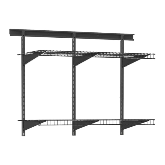
01-82371-00
Whichever load reaches
capacity first:
Maximum Shelving Load*: 100 lbs/ft
Maximum 40 in. Hang Track Load*: 700 lbs
Maximum System Load*: 600 lbs
(See pages 6)
*Static Load Evenly Distributed. Must be installed per manufacturer's
specifications or weight load capacity does not apply.
BEFORE BEGINNING
• Please read all instructions carefully.
• Familiarize yourself with all parts (see "PARTS INCLUDED WITH KIT") and check quantities.
• Follow all safety precautions (see "SAFETY PRECAUTIONS").
• Follow all manufacturer installation requirements in order to comply with the
advertised weight load specifications.
© 2020 ClosetMaid LLC | Ocala, FL 34471 | 1-800-874-0008 | www.closetmaid.com
INSTALLATION INSTRUCTIONS
What you will need:
2 SHELF KIT (3 FT.)
35354
02/20
1
Advertisement

Related Manuals for ClosetMaid MAXLOAD 35354


Summary of Contents for ClosetMaid MAXLOAD 35354
- Page 1 • Familiarize yourself with all parts (see “PARTS INCLUDED WITH KIT”) and check quantities. • Follow all safety precautions (see “SAFETY PRECAUTIONS”). • Follow all manufacturer installation requirements in order to comply with the advertised weight load specifications. © 2020 ClosetMaid LLC | Ocala, FL 34471 | 1-800-874-0008 | www.closetmaid.com...
- Page 2 Screw 3/ 16 in. (9) 90274 Toggle Bolt 3/ 16 in. (9) Panhead Screw #12 x 2 in. (9) 90688 Anchor 1/4 in. (9) End Cap (24) 90603 © 2020 ClosetMaid LLC | Ocala, FL 34471 | 1-800-874-0008 | www.closetmaid.com...
- Page 3 Consumer Affairs at 1-800-874-0008. Manufacturer Warranty Manufacturer will replace any missing or damaged part due to manufacturer defect for one year after purchase. Please have proof of purchase for warranty claims. © 2020 ClosetMaid LLC | Ocala, FL 34471 | 1-800-874-0008 | www.closetmaid.com...
- Page 4 CAUTION: To avoid personal injury, use care and a safe, sturdy stepping stool to position hang track. Bottom © 2020 ClosetMaid LLC | Ocala, FL 34471 | 1-800-874-0008 | www.closetmaid.com...
- Page 5 STUD STUD STUD Hit studs in at least 3 holes. STUD STUD STUD Use a toggle bolt on each hole that does not hit a stud. TOGGLE TOGGLE © 2020 ClosetMaid LLC | Ocala, FL 34471 | 1-800-874-0008 | www.closetmaid.com...
- Page 6 C) When track is at desired height and level, mark each screw hole on the wall using a pencil. D) For this kit, the minimum hang track installed height is 35 in. from the top of your baseboard. 35 in. © 2020 ClosetMaid LLC | Ocala, FL 34471 | 1-800-874-0008 | www.closetmaid.com...
- Page 7 This will enhance the security of the hang track mounting. IMPORTANT: SECURE HARDWARE THROUGH EACH HOLE! DRYWALL = TOGGLE BOLT DRILL 1/2 IN. HOLES. STUD = SCREW © 2020 ClosetMaid LLC | Ocala, FL 34471 | 1-800-874-0008 | www.closetmaid.com...
- Page 8 B) Insert anchors into 1/4 in. predrilled holes and secure hang track with panhead screws. IMPORTANT: SECURE HARDWARE THROUGH EACH HOLE! SCREWS AND ANCHORS ONLY DRILL 1/4 IN. HOLES. © 2020 ClosetMaid LLC | Ocala, FL 34471 | 1-800-874-0008 | www.closetmaid.com...
- Page 9 MORE than 16 in. apart and a MINIMUM of 2 in. in from end of hang track. Adjust standards evenly for your specific closet width. 2 in. 16 in. 16 in. © 2020 ClosetMaid LLC | Ocala, FL 34471 | 1-800-874-0008 | www.closetmaid.com...
- Page 10 Secure each standard to the wall using recommended hardware as shown. Use a Phillips screwdriver to tighten each panhead screw or bolt. STUD CONCRETE DRYWALL DRILL 1/2 in. HOLE DRILL 1/4 in. HOLES 16 in. 16 in. 10 © 2020 ClosetMaid LLC | Ocala, FL 34471 | 1-800-874-0008 | www.closetmaid.com...
- Page 11 INSTALL BRACKETS Attach a bracket to each standard where you expect to place a shelf. © 2020 ClosetMaid LLC | Ocala, FL 34471 | 1-800-874-0008 | www.closetmaid.com...
- Page 12 Place shelf on brackets. Allow an equal overhang (from brackets) on both sides. Measure amount to be cut. Remove shelf and cut with hacksaw or bolt cutter. Do not make cuts where vertical spacers are on front lip of shelf. Never allow more than a 6 in. overhang. 6 in. 12 © 2020 ClosetMaid LLC | Ocala, FL 34471 | 1-800-874-0008 | www.closetmaid.com...
- Page 13 1) Pull shelf forward and allow front to “drop” over nose of brackets (nose of each bracket will fit between wires). 2) Push shelf backwards so back wire fits into bracket slots. 3) Firmly pull shelf forward at each bracket location to lock shelf into place. © 2020 ClosetMaid LLC | Ocala, FL 34471 | 1-800-874-0008 | www.closetmaid.com...
- Page 14 10843 Medium Cabinet INSTALLATION INSTRUCTIONS 01-18643-00 06/20 © 2020 ClosetMaid LLC | Ocala, FL 34471 | 1-800-874-0008 | www.closetmaid.com...
-
Page 15: Before Beginning
SAFETY PRECAUTIONS BEFORE BEGINNING • Please read all instructions carefully. • Familiarize yourself with all parts (see “PARTS”) and check quantities. • Follow all safety precautions (see “SAFETY PRECAUTIONS”). WARNING • • CHOKING HAZARD FOR SMALL CHILDREN. This unit DO NOT USE THIS UNIT AS A TELEVISION STAND. contains small parts which could be a choking hazard for Serious bodily injury and/or damage to personal small children. -
Page 16: Tools Required
PARTS Call 1-800-874-0008 for parts and service. For faster service, have the style number ready when calling. TOOLS REQUIRED #3 Phillips Screwdriver 10 mm. Wrench HARDWARE PROVIDED Name Qty. ST6.3 x 12 mm. Screw 28 + 2 Electrical Bushing M6-1.0 x 12 mm. Bolt... - Page 17 PARTS Call 1-800-874-0008 for parts and service. For faster service, have the style number ready when calling. PRODUCT Name Part # Name Part # Left Side Panel 35857 Caster without Brake 20624 Right Side Panel 35858 Caster with Brake 20624 Back Panel 35859 Bottom Shelf...
- Page 18 STEP 1 Attach side panels to back panel. Align both side panels (A & B) with the back panel (C) as shown. Slide the metal tabs on the back panel (C) into the matching slots on the side panels (A & B). Pull the side panels down to secure the tabs in place.
- Page 19 STEP 2 Attach top panel. Align top panel (D) with the top of the unit as shown. Push in to secure into place. Make sure that all the triangular tabs on the back and side panels completely snap into place in the square holes on the top panel. *Please note location of predrilled holes on each part.
- Page 20 STEP 3 Attach bottom panel. Align bottom panel (E) with the bottom of the unit as shown. Push in to secure into place. Make sure that all the triangular tabs on the back and side panels completely snap into place in the square holes on the bottom panel. *Please note location of predrilled holes on each part.
- Page 21 STEP 4 Attach door frame. Align the door frame (F) with the front of the unit as shown. Please note that the holes on the bottom of the door frame will match up with the upper holes on the bottom panel. Use a #3 Phillips screwdriver to secure the door frame to the unit using twelve ST6.3 x 12 mm.
- Page 22 STEP 5 Attach casters. Align two casters without brakes (G) with the lower holes on the bottom panel (E). Use a #3 Phillips screwdriver to secure the casters to the unit using eight ST6.3 x 12 mm. screws (AA). Align two casters with brakes (H) with the upper holes on the bottom panel (E). Use a #3 Phillips screwdriver to secure the casters to the unit using eight ST6.3 x 12 mm.
- Page 23 STEP 6 Attach shelves. Stand the unit up on the casters. Place the bottom shelf (I) inside the unit at the bottom. Push down to secure into place, making sure all metal tabs are connected. Please note that the bottom shelf is larger than the inner shelf and will rest on the lowest three metal tabs on the back panel.
- Page 24 STEP 7 (Optional) Attach unit to workbench top. Note: This step is only if you are planning to attach a workbench top (sold separately). If not, skip to next step. Place cabinets next to each other and align workbench top with the top of the units. For each cabinet, use a 10 mm. wrench to attach four M6-1.0 x 12 mm.
- Page 25 STEP 8 Attach electrical bushing. Align the electrical bushing (BB) with the large circle on the back of the unit. Push in to secure. *Please note location of predrilled holes on each part.
- Page 26 STEP 9 Attach doors. Align the right door (L) with the right side of the unit. Place the bottom lock of the door in the hole on the bottom of the door frame. Pull the top lock down, align it with the hole on the top of the door frame, and push up to lock into place.
- Page 27 10842 Medium Cabinet with Drawer INSTALLATION INSTRUCTIONS 01-18642-00 06/20 © 2020 ClosetMaid LLC | Ocala, FL 34471 | 1-800-874-0008 | www.closetmaid.com...
-
Page 28: Before Beginning
SAFETY PRECAUTIONS BEFORE BEGINNING • Please read all instructions carefully. • Familiarize yourself with all parts (see “PARTS”) and check quantities. • Follow all safety precautions (see “SAFETY PRECAUTIONS”). WARNING • • CHOKING HAZARD FOR SMALL CHILDREN. This unit DO NOT HANG THIS UNIT ON THE WALL. The product contains small parts which could be a choking hazard for structure is not designed for wall hanging. -
Page 29: Tools Required
PARTS Call 1-800-874-0008 for parts and service. For faster service, have the style number ready when calling. TOOLS REQUIRED #3 Phillips Screwdriver 10 mm. Wrench HARDWARE PROVIDED Name Qty. Left Drawer Glide Right Drawer Glide ST6.3 x 12 mm. Screw 28 + 2 Electrical Bushing M6-1.0 x 12 mm. - Page 30 PARTS Call 1-800-874-0008 for parts and service. For faster service, have the style number ready when calling. PRODUCT Name Part # Name Part # Left Side Panel 35857 Door Frame 35864 Right Side Panel 35858 Caster Without Brake 20624 Drawer 35861 Caster With Brake 20624...
- Page 31 STEP 1 Remove inner drawer glides from outer drawer glides. For the left drawer glide (AA), extend the inner glide (AA1) from the outer glide (AA2). Push down on the locking tab to unlock the inner glide. Pull the inner glide out to remove. For the right drawer glide (BB), extend the inner glide (BB1) from the outer glide (BB2).
- Page 32 STEP 2 Attach outer glides to side panels. Align the metal tabs on the outer left glide (AA2) with the holes on the interior of the left side panel (A). With the tabs in the holes, pull the glide to the right to secure the right tab in place, and then pull down to secure the left tab. Repeat steps for the outer right glide (BB2) and right side panel (B).
- Page 33 STEP 3 Attach inner glides to drawer. Align the metal tabs on the inner left glide (AA1) with the holes on the left exterior of the drawer (C). With the tabs in the holes, pull the glide to the left to secure the left tab in place, and then pull up to secure the right tab. Repeat steps for the inner right glide (BB1) on the opposite side.
- Page 34 STEP 4 Attach side panels to back panel. Align both side panels (A & B) with the back panel (D) as shown. Slide the metal tabs on the back panel (D) into the matching slots on the side panels (A & B). Pull the side panels down to secure the tabs in place.
- Page 35 STEP 5 Attach top panel. Align top panel (E) with the top of the unit as shown. Push down to secure into place. Make sure that all the triangular tabs on the back and side panels completely snap into place in the square holes on the top panel. *Please note location of predrilled holes on each part.
- Page 36 STEP 6 Attach bottom panel. Align bottom panel (F) with the bottom of the unit as shown. Push down to secure into place. Make sure that all the triangular tabs on the back and side panels completely snap into place in the square holes on the bottom panel. *Please note location of predrilled holes on each part.
- Page 37 STEP 7 Attach door frame. Align the door frame (G) with the front of the unit as shown. Please note that the holes on the bottom of the door frame will match up with the upper holes on the bottom panel. Use a #3 Phillips screwdriver to secure the door frame to the unit using twelve ST6.3 x 12 mm.
- Page 38 STEP 8 Attach casters. Align two casters without brakes (H) with the lower holes on the bottom panel (F). Use a #3 Phillips screwdriver to secure the casters to the unit using eight ST6.3 x 12 mm. screws (CC). Align two casters with brakes (I) with the upper holes on the bottom panel (F). Use a #3 Phillips screwdriver to secure the casters to the unit using eight ST6.3 x 12 mm.
- Page 39 STEP 9 Attach bottom shelf. Stand the unit up on the casters. Place the bottom shelf (J) inside the unit at the bottom. Push down to secure into place, making sure all metal tabs are connected. Please note that the bottom shelf will rest on the lowest three metal tabs on the back panel. *Please note location of predrilled holes on each part.
- Page 40 STEP 10 (Optional) Attach unit to workbench top. Note: This step is only if you are planning to attach a workbench top (sold separately). If not, skip to next step. Place cabinets next to each other and align workbench top with the top of the units. For each cabinet, use a 10 mm. wrench to attach four M6-1.0 x 12 mm.
- Page 41 STEP 11 Attach electrical bushing. Align the electrical bushing (DD) with the large circle on the back of the unit. Push in to secure. *Please note location of predrilled holes on each part.
- Page 42 STEP 12 Insert drawer. Align the inner glides of the drawer (C) with the outer glides inside the top of the unit. Push in to attach drawer. *Please note location of predrilled holes on each part.
- Page 43 STEP 13 Attach doors. Align the right door (L) with the right side of the unit. Place the bottom lock of the door in the hole on the bottom of the door frame. Pull the top lock down, align it with the hole on the top of the door frame, and push up to lock into place.
- Page 44 10840 30 in. Cabinet INSTALLATION INSTRUCTIONS 01-18640-00 06/20 © 2020 ClosetMaid LLC | Ocala, FL 34471 | 1-800-874-0008 | www.closetmaid.com...
- Page 45 SAFETY PRECAUTIONS BEFORE BEGINNING • Please read all instructions carefully. • Familiarize yourself with all parts (see “PARTS”) and check quantities. • Follow all safety precautions (see “SAFETY PRECAUTIONS”). WARNING • • CHOKING HAZARD FOR SMALL CHILDREN. This unit DO NOT MOUNT OR ATTACH ANYTHING TO THE SIDES, REAR, OR FRONT OF THE UNIT.
- Page 46 PARTS Call 1-800-874-0008 for parts and service. For faster service, have the style number ready when calling. TOOLS REQUIRED Level Drill 5/16 in. Masonry Hammer #2 and #3 Phillips Drill Bit Screwdrivers HARDWARE PROVIDED Name Qty. ST6.3 x 12 mm. Screw 32 + 2 Electrical Bushing Concrete Anchor...
- Page 47 PARTS Call 1-800-874-0008 for parts and service. For faster service, have the style number ready when calling. PRODUCT Name Part # Name Part # Left Side Panel 35832 Adjustable Feet 20620 Right Side Panel 35834 Bottom Shelf 35836 Back Panel 35835 Inner Shelf 35837...
- Page 48 STEP 1 Attach side panels to back panel. Align both side panels (A & B) with the back panel (C) as shown. Slide the metal tabs on the back panel (C) into the matching slots on the side panels (A & B). Pull the side panels down to secure the tabs in place.
- Page 49 STEP 2 Attach top panel. Align top panel (D) with the top of the unit as shown. Push in to secure into place. Make sure that all the triangular tabs on the back and side panels completely snap into place in the square holes on the top panel. *Please note location of predrilled holes on each part.
- Page 50 STEP 3 Attach bottom panel. Align bottom panel (E) with the bottom of the unit as shown. Push in to secure into place. Make sure that all the triangular tabs on the back and side panels completely snap into place in the square holes on the bottom panel. *Please note location of predrilled holes on each part.
- Page 51 STEP 4 Attach door frame. Align the door frame (F) with the front of the unit as shown. Please note that the holes on the bottom of the door frame will match up with the upper holes on the bottom panel. Use a #3 Phillips screwdriver to secure the door frame to the unit using sixteen ST6.3 x 12 mm.
- Page 52 STEP 5 Attach adjustable feet. Align the four adjustable feet (G) with the holes on the bottom panel. Use a #3 Phillips screwdriver to secure the feet to the unit using sixteen ST6.3 x 12 mm. screws (AA). #3 Phillips x 16 *Please note location of predrilled holes on each part.
- Page 53 STEP 6 Attach electrical bushing. Stand the unit up on the feet. Align the electrical bushing (BB) with the large circle on the back of the unit. Push in to secure. *Please note location of predrilled holes on each part.
- Page 54 STEP 7a Secure unit via concrete mounting. Please use an assistant to help hold the unit during the mounting process to avoid possible tip over. Align the unit with the location on the wall where you plan to mount it. Ensure unit is level and change adjustable feet height if necessary.
- Page 55 STEP 7b Secure unit via stud mounting. Please use an assistant to help hold the unit during the mounting process to avoid possible tip over. Locate studs and align the unit with the location on the wall where you plan to mount it. Ensure unit is level and change adjustable feet height if necessary.
- Page 56 Please use an assistant to help hold the unit during the mounting process to avoid possible tip over. Please note that this mounting option requires separate hardware not included with this product. The ClosetMaid drywall mounting package (SKU: 2062800) is recommended for a secure fit.
- Page 57 STEP 8 Attach shelves. Place the bottom shelf (H) inside the unit at the bottom. Push down to secure into place, making sure all metal tabs are connected. Please note that the bottom shelf is larger than the inner shelves and will rest on the lowest three metal tabs on the back panel.
- Page 58 STEP 9 Attach doors. Align the right door (K) with the right side of the unit. Place the bottom lock of the door in the hole on the bottom of the door frame. Pull the top lock down, align it with the hole on the top of the door frame, and push up to lock into place.
Need help?
Do you have a question about the MAXLOAD 35354 and is the answer not in the manual?
Questions and answers