
Related Manuals for Shihlin electric SL3 Series


Summary of Contents for Shihlin electric SL3 Series
-
Page 1: Table Of Contents
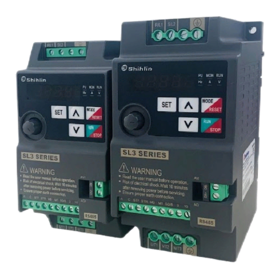
Shihlin Electric General Inverters SL3 Series User Manual Compact SL3-021-0.4K~2.2K SL3-043-0.4K~2.2K MANUAL GUIDE DELIVERY CHECK INVERTER INTRODUCTION BASIC OPERATION PARAMETER DESCRIPTION INSPECTION AND MAINTENANCE APPENDIX... -
Page 3: Manual Guide
1. MANUAL GUIDE 1.1 Safety instructions Thank you for choosing Shihlin inverters SL3 series. This user manual introduces how to use the product correctly. Please read the user manual carefully before using the product. In addition, please use the product after understanding the safety instructions. -
Page 4: Delivery Check
Table of contents 1.2 Table of contents User Manual .................................... 1 1. MANUAL GUIDE ................................1 1.1 Safety instructions ..............................1 1.2 Table of contents ..............................2 1.3 Definitions of terminologies ........................... 10 2. DELIVERY CHECK ................................11 2.1 Nameplate instruction ............................11 2.2 Type instruction .............................. -
Page 5: Basic Operation
Table of contents 3.5.3 Installation notice ..........................18 3.5.4 EMC installation instructions......................21 3.6 Peripheral devices ..............................22 3.6.1 System Wire Arrangement .......................22 3.6.2 No-fuse breaker and magnetic contactor ..................23 3.7 Terminal wire arrangement ........................... 24 3.7.1 Main circuit Terminals ........................25 3.7.2 Main circuit wiring and terminal specification ..................26 3.7.3 Ground .............................26 3.7.4 RFI filter............................26 3.7.5 Control circuit ...........................27... -
Page 6: Parameter Description
Table of contents 4.3.1 Basic operation steps for PU mode (00-16(P.79)=0 or 1) .............37 4.3.2 Basic operation steps for external mode (00-16(P.79)=0 or 2) .............37 4.3.3 Basic operation steps for JOG mode (00-16(P.79)=0 or 1) ............38 4.3.4 Basic operation steps for communication mode (00-16(P.79)=3) ..........38 4.3.5 Basic operation steps for combined mode 1 (00-16(P.79)=4) ............38 4.3.6 Basic operation steps for combined mode 2 (00-16(P.79)=5) ............38 4.3.7 Basic operation steps for combined mode 3(00-16(P.79)=6) ............39... - Page 7 Table of contents 5.1.10 Operation mode selection ......................56 5.1.11 Motor control mode selection ......................57 5.1.12 50/60Hz switch selection .......................58 5.1.13 Parameter mode setting ........................58 5.2 Basic Parameter Group 01 ........................... 59 5.2.1 Limiting the output frequency ......................61 5.2.2 Base frequency, base voltage ......................62 5.2.3 Acceleration/deceleration time setting .....................63 5.2.4 Torque boost V/F ..........................66 5.2.5 Starting frequency ..........................66...
- Page 8 Table of contents 5.4 Digital input/ output parameter group 03 ......................85 5.4.1 Digital input terminals function selection ..................88 5.4.2 Digital output terminals function selection ..................92 5.4.3 Terminal logic selection ........................93 5.4.4 Digital output signal delay ........................94 5.4.5 Digital input signal filter ........................94 5.4.6 Digital input terminal enable when power on ...................94 5.4.7 Output frequency detection......................95 5.4.8 Zero current detection ........................96...
- Page 9 Table of contents 5.8.1 Shihlin protocol and Modbus protocol ..................114 5.8.2 Communication EEPROM write selection ..................129 5.9 PID parameter group 08 ............................130 5.9.1 PID function selection ........................131 5.9.2 PID parameter group ........................131 5.9.3 PID pressure range setting ......................135 5.9.4 PID analog signal feedback loss ....................
-
Page 10: Inspection And Maintenance
Table of contents 5.11.3 Vibration inhibition ........................151 5.11.4 Current detection option ......................151 5.12 User registered parameter 15 .......................... 152 5.12.1 User registered parameter ......................153 6. INSPECTION AND MAINTENANCE ........................... 155 6.1 Inspection item ..............................155 6.1.1 Daily inspection item ........................155 6.1.2 Replacement parts ........................ - Page 11 Table of contents 7.5.2 DU06 Keypad ..........................197 7.5.3 DU08 Keypad ..........................198 7.5.4 DU10 Keypad ..........................200 7.5.5 PU302 Keypad ........................... 201 7.5.6 CBL:Data transmission line (for use with the above keypads) ..........203 7.6 Appendix 6 European Specification Compatibility Description..............204 8.
- Page 12 Definitions of terminologies 1.3 Definitions of terminologies Output frequency, target frequency, steady output frequency The actual output current frequency of inverter is called “output frequency.” The frequency set by user (via built-in keypad, multi-speed terminals, voltage signal, and current signal or ...
- Page 13 2.6A 0~599Hz L3ANCAS18A0001 VER:0.100A Hardware and Firmware version Serial number IP20 Protection level Suzhou Shihlin Electric & Engineering Co.,Ltd MADE IN CHINA 2.2 Type instruction SL3-043-0.75K-xy None: General model -xy : Customized or dedicated or region difference Suitable motor :...
- Page 14 Electric specification 3. INVERTER INTRODUCTION 3.1 Electric specification 3.1.1 440V series three-phase Frame Model SL3-043-□□□K-□□ 0.75 Rated output capacity (kVA) Rated output current (A) Applicable motor capacity (HP) Inverter Applicable motor capacity (kW) 0.75 Output Overload current rating 150% 60 seconds, 200% 1 seconds (inverse-time characteristics) Carrier frequency (kHz) 1~15kHz Maximum output voltage...
- Page 15 Electric specification 3.1.2 220V series single phase Frame Model SL3-021-□□□K-□□ 0.75 Rated output capacity (kVA) Rated output current (A) Applicable motor capacity (HP) Inverter Applicable motor capacity (kW) 0.75 Output Overload current rating 150% 60 seconds, 200% 1 seconds (inverse-time characteristics) Carrier frequency (kHz) 1~15kHz Maximum output voltage...
- Page 16 General specification 3.2 General specification Control method V/F control Output frequency range 0.00~599.00Hz Frequency Digital setting 0.01Hz setting Analog setting Maximum output frequency±0.1%. resolution Digital setting Maximum target frequency±0.01%. Output frequency Analog setting Maximum target frequency±0.1%. accuracy Starting torque 150% / 5Hz automatic torque boost V/F characteristics Constant torque curve, variable torque curve,five-point VF curve Acceleration / deceleration...
- Page 17 Appearance and dimensions 3.3 Appearance and dimensions 3.3.1 Frame A unit:mm Model SL3-021-0.4K SL3-021-0.75K 42.5 (tighten torque 20~25kgf.cm) SL3-021-1.5K INVERTER INTRODUCTION 15...
- Page 18 Appearance and dimensions 3.3.2 Frame B unit:mm Model SL3-021-2.2K SL3-043-0.4K SL3-043-0.75K 59.5 129.5 42.5 (tighten torque 20~25kgf.cm) SL3-043-1.5K SL3-043-2.2K INVERTER INTRODUCTION 16...
- Page 19 Name of each component 3.4 Name of each component 3.4.1 Frame A/B *1.A Frame:SL3-021-0.4K,SL3-021-0.75K,SL3-021-1.5K *2.B Frame:SL3-021-2.2K,SL3-043-0.4K,SL3-043-0.75K,SL3-043-1.5K,SL3-043-2.2K Mounting hole Built-in keypad VR knob Warning sign Product nameplate External keypad connector INVERTER INTRODUCTION 17...
- Page 20 Installation and wiring 3.5 Installation and wiring 3.5.1 Transportation Hold the body when carrying and don’t only hold the cover or any part of the inverter, otherwise it may drop down. 3.5.2 Stockpile The product must be placed in the packaging box before installation. In order to make the product conform to the scope of warranty of the company and facilitate maintenance in the future, please pay attention to the following matters when storing if the inverter will not be used temporarily: 1.
- Page 21 EMC installation instructions Please install the inverter vertically in order not to reduce the heat dissipation effect: (a) Vertical installation (b) Horizontal installation (c) Transverse installation Please follow the installation restrictions shown below to ensure enough ventilation space for inverter cooling and wiring space: Arrangement of single or paralleling inverter:...
- Page 22 Installation and wiring Arrangement of multiple inverters: Inverter Inverter Inverter Inverter Guide Guide Guide Inverter Inverter Enclosure Enclosure (a) Horizontal arrangement (b) Vertical arrangement Note: 1. When it is inevitable to arrange inverters vertically to minimize space,install guides since heat from the bottom inverters can increase the temperature on the top inverters, causing inverter failures.
- Page 23 EMC installation instructions 3.5.4 EMC installation instructions Just as other electrical and electronic equipment, an inverter is the source of electromagnetic interference and an electromagnetic receiver when working with a power system. The amount of electromagnetic interference and noise is determined by the working principles of an inverter.
- Page 24 Peripheral devices 3.6 Peripheral devices 3.6.1 System Wire Arrangement Power Please provide power Molded case circuit Power specified in manual. breaker (MCCB) or earth leakage current breaker (ELB) Molded case When power ON there might circuit breaker Magnetic contactor be huge inrush current flows to (MCCB) or (MC) inverter.
- Page 25 Peripheral devices 3.6.2 No-fuse breaker and magnetic contactor Applicable no-fuse switch Applicable electromagnetic Inverter model Motor capacity Power source capacity (NFB/MCCB) type contactor (MC) type (Shihlin Electric) (Shihlin Electric) SL3-043-0.4K 440V 0.5HP 1.5kVA BM30SN3P3A S-P11 SL3-043-0.75K 440V 1HP 2.5kVA BM30SN3P5A S-P11 SL3-043-1.5K...
- Page 26 Terminal wire arrangement 3.7 Terminal wire arrangement Main circuit terminal Control circuit terminal NFB/MCCB Power MOTOR reactor Input Main circuit Control circuit Digital signal input Forward run command Red light Relay output Reverse run command VDC30V Multi-speed command 1 VAC250V Multi-speed command 2 SD/5 RS485 communication...
- Page 27 Terminal wire arrangement 3.7.1 Main circuit Terminals Description Main circuit terminals description R/L1-S/L2-T/L3 Connect to commercial power supply U/T1-V/T2-W/T3 Connect to three-phase induction motor. Connect to ground Terminal layout of the main circuit terminals . SL3-021-0.4K,SL3-021-0.75K,SL3-021-1.5K,SL3-021-2.2K SL3-043-0.4K,SL3-043-0.75K,SL3-043-1.5K,SL3-043-2.2K ...
- Page 28 Wrong Best Acceptable 3.7.4 RFI filter SL3 series inverters are equipped with built-in RFI filters. These filters are effective in reducing electromagnetic interference, but to meet CE standard, please refer to section 3.5.4 for installation and wiring. INVERTER INTRODUCTION 26...
- Page 29 Terminal wire arrangement 3.7.5 Control circuit Control terminal name Terminal type Terminal name Function instructions Terminal specifications Input impedance: 2.4 kΩ Digital signal These are multi-function control terminals, a Action current : 3 mA (when 24 input total of 4. VDC) Maximum frequency: 1kHz +10.5±0.5V...
- Page 30 Terminal wire arrangement (2) Insert the wire to blade terminal and crimping. Insert wires to a blade terminal, and check that the wires come out for about 0 to 0.5 mm from a sleeve. Check the condition of the blade terminal after crimping. Do not use a blade terminal of which the crimping is inappropriate, or the face is damaged.
- Page 31 Replacement procedure of fan 3.8 Replacement procedure of fan If the fan is broken, please send the unit back to our factory to repair. INVERTER INTRODUCTION 29...
- Page 32 Component name of keypad 4. BASIC OPERATION 4.1 Component name of keypad ( b ) ( c ) 8.8.8.8.8 Operation parts Name Content PU: On when in PU/JOGoperation mode, flickers in H1~H5 Operation mode indicator operation mode. Keypad status indicator MON:On to indicate keypad is in monitoring mode RUN indicator Flickers when running.
- Page 33 Operation modes of inverter 4.2 Operation modes of inverter Operation modes are related to signal source for the target frequency and signal source for motor starting. In Shihlin SL3 inverter there are nine kinds of operation modes: “PU mode( )”, “JOG mode( )”, “External mode(...
- Page 34 Operation modes of inverter 4.2.1 Flow chart for switching operation mode OP n d J OG J OG Note: 1. In “PU mode”, keypad screen displays and the indicator in will light up. 2. In “External mode”, keypad screen displays 3.
- Page 35 Operation modes of inverter 4.2.3 Operation flow chart for monitoring mode ● Take External mode as an example: 0 0 0 0 0 0 0 0 0 Note: 1. In “monitoring output frequency” mode, indicator in will light up, and the screen will display current output frequency.
- Page 36 Operation modes of inverter 4.2.4 Operation flow chart for frequency setting 0 0 0 0 0 0 Note: 1. When inverter is running, use key on built-in keypad to change the target frequency setting. 2. Under frequency setting mode, indicator in will not light up.
- Page 37 Operation modes of inverter 4.2.6 Operation flow chart for HELP mode HE L P EH 1 5 Flicker P r Gr over 0.5s Flicker E r . C over 0.5s Flicker r E ST over 0.5s Flicker AL L C over 0.5s P r Cr Flicker...
- Page 38 Operation modes of inverter 4.2.7 Operation flow chart for changing motor rotation direction Note: 1. The operation mode is valid when signal source for motor starting comes from keypad. BASIC OPERATION 36...
- Page 39 Basic operation steps for different modes 4.3 Basic operation steps for different modes 4.3.1 Basic operation steps for PU mode (00-16(P.79)=0 or 1) Step Description • Switch operation mode to PU mode, and indicator in will light up. Note: 1. When 00-16(P.79) =0, the inverter will first be in external mode after power on or reset. 2.
- Page 40 Basic operation steps for different modes 4.3.3 Basic operation steps for JOG mode (00-16(P.79)=0 or 1) Step Description •Switch operation mode to JOG mode and indicator in will light up, the display shows Note: 1. For detailed operating procedures for the monitor mode, please refer to section 4.2. •...
- Page 41 Basic operation steps for different modes 4.3.7 Basic operation steps for combined mode 3(00-16(P.79)=6) Step Description • In Combined Mode 3, indicator in will flicker. Note: 1. For detailed operation procedures for monitor mode, please refer to section 4.2. Default priority from high to low: •...
- Page 42 Operation 4.4 Operation 4.4.1 Check and preparation before running Before running, the following shall be checked: 1. Check if the wiring is correct. Inverter output terminals (U/T1, V/T2, W/T3) cannot be connected to the power. Confirm that grounding terminal ( ) is well grounded.
- Page 43 Operation 4.4.3 Test run Check cables and abnormalities before the test run. After power on, the inverter is in external mode. 1. After power on, make sure no alarm on built-in keypad, make sure indicator is on. 2. Connect a switch between STF/SD and STR/SD. 3.
- Page 44 System parameter group 00 5. PARAMETER DESCRIPTION 5.1 System parameter group 00 Parameter Group Name Setting Range Default Page Number 00-00 P.90 Inverter model Read only 00-01 P.188 Firmware version Read only 0: Off 1: Clear alarm history (P.996=1) 2: Reset inverter (P.997=1) P.996 Parameter 00-02...
- Page 45 System parameter group 00 Parameter Group Name Setting Range Default Page Number 8: Signal value (mA) of 3-5 input terminals (mA/V). 9: Output power (kW). 10:Reserved 11: Forward reverse rotation signal. 1: forward rotation 2: reverse rotation 0: stop. Multi-function 00-07 P.161 12: NTC temperature (℃)
- Page 46 System parameter group 00 Parameter Group Name Setting Range Default Page Number 0: Forward/reverse rotation are both permitted. Prevent 1: Prevent reverse rotation (Giving reverse signal decelerates 00-15 P.78 forward/reverse and stops the motor). rotation selection 2: Prevent forward rotation (Giving forward signal decelerates and stops the motor).
- Page 47 System parameter group 00 5.1.1 Inverter information For checking inverter model, control board firmware version, etc. Parameter Name Default Setting Range Content 00-00 Inverter model Read only Read only P.90 00-01 Firmware version Read only Read only Inverter control board firmware version P.188 Inverter model ...
- Page 48 System parameter group 00 5.1.2 Parameter restoration Set parameters back to default. Parameter Name Default Setting Range Content Clear alarm history (P.996=1) Reset inverter (P.997=1) Parameter 00-02 Restore all parameters to default (P.998=1) restoration Restore some parameters to default 1 (P.999=1) Restore some parameters to default 2 (P.999=2) Restore some parameters to default 3 (P.999=3) Setting...
- Page 49 System parameter group 00 Group Name 00-21 P.300 Motor control mode selection 02-25 P.198 Terminal 3-5 minimum input current/ voltage 02-26 P.199 Terminal 3-5 maximum input current/ voltage Percentage corresponds to terminal 3-5 minimum input current/ 02-27 P.196 voltage Percentage corresponds to terminal 3-5 maximum input current/ 02-28 P.197 voltage...
- Page 50 System parameter group 00 5.1.3 Parameter protection It is used to select whether parameters can be written to prevent changing parameter values due to misoperation. Parameter Name Default Setting Range Content Parameters can be written only when the motor stops. Selection of Parameters cannot be written.
- Page 51 System parameter group 00 00-16 P.79 Operation mode selection When running, the parameters below can be written.(00-03(P.77)=“2” ) Exception When running, the parameters below cannot be written: Group Name Group Name 00-00 P.90 Inverter model 06-27 P.292 Total inverter operation time (minutes) 00-01 P.188 Firmware version...
- Page 52 System parameter group 00 5.1.4 Monitoring function Item to monitor on built-in keypad can be selected. Parameter Name Default Setting Range Content When inverter starts, built-in keypad enters monitor mode automatically, screen displays output frequency (Note 1 ). When inverter starts, built-in keypad displays target frequency.
- Page 53 System parameter group 00 Keypad monitoring selection Display Display current pressure and feedback pressure of the constant pressure system in percentage (00-06(P.110)=“3” ) The screen shows two sections. A decimal point is used to separate the boundaries, on the left is the target pressure and on the right is the feedback pressure of the constant pressure system in percentage.
- Page 54 System parameter group 00 5.1.5 Speed display In “monitoring output frequency” mode, the screen displays corresponding machine speed. Parameter Name Default Setting Range Content Display output frequency(not mechanical speed) 00-08 Speed display 0.1~5000.0 When 00-09(P.259)=1 P.37 1~50000 When 00-09(P.259)=0 Speed display unit is 1 00-09 Speed display unit...
- Page 55 System parameter group 00 5.1.6 Built-in keypad set target frequency selection Parameter Name Default Setting Range Content Use up down button on built-in or external keypad to set XXX0 frequency XXX1 Use keypad knob on external keypad to set frequency XXX2 Use keypad knob on built-in keypad to set frequency Built-in keypad set...
- Page 56 System parameter group 00 5.1.7 PWM carrier frequency The motor sound can be changed by adjusting PWM carrier frequency properly. Parameter Name Default Setting Range Content 00-11 Carrier frequency 1~15 P.72 When 00-11(P.72)<5,Soft-PWM is on(only apply to V/F control) 00-12 Soft-PWM carrier When 00-11(P.72)>9, if the IGBT temperature is high, carrier...
- Page 57 System parameter group 00 5.1.8 Stop operation selection Select the inverter stop method Parameter Name Default Setting Range Content Idling brake 00-13 Idling brake / DC P.71 brake DC brake Press button and inverter stop running in PU and 00-14 function H2(combine mode 2) mode...
- Page 58 System parameter group 00 5.1.9 Forward/reverse rotate prevent function Set this parameter to limit the motor rotation to only one direction, and prevent reverse rotation fault resulting from the incorrect input of the start signal. Parameter Name Default Setting Range Content Forward/reverse rotation are both permitted.
- Page 59 System parameter group 00 5.1.11 Motor control mode selection Choose control mode for the AC motor Parameter Name Default Setting Range Content 00-21 Motor control mode Induction motor V/F control P.300 selection Reserved Setting Motor control mode Induction motor V/F control: user can design proportion of V/F as required and can control multiple motors ...
- Page 60 System parameter group 00 5.1.12 50/60Hz switch selection Select between 50Hz or 60Hz according to different power source frequency or default motor frequency, this effects all frequency-related parameters. Parameter Name Default Setting Range Content Frequency related parameter default value is 60Hz. 00-24 50Hz/60Hz switch...
- Page 61 Basic Parameter Group 01 5.2 Basic Parameter Group 01 Parameter Group Name Setting Range Default Page Number 01-00 Maximum frequency 0.00~01-02(P.18)Hz 120.00Hz 01-01 Minimum frequency 0~120.00Hz 0.00Hz 01-02 P.18 High-speed maximum 01-00(P.1)~599.00Hz 120.00Hz frequency 50Hz system setting: 0~599.00Hz 50.00Hz 01-03 Base frequency 60Hz system setting: 0~599.00Hz 60.00Hz...
- Page 62 Basic Parameter Group 01 Parameter Group Name Setting Range Default Page Number 0~599.00Hz 01-21 P.96 Frequency jump 3B 99999 99999: Off 0~360.00s/0~3600.0s 01-22 P.44 Second acceleration time 99999 99999: Off 0~360.00s/0~3600.0s 01-23 P.45 Second deceleration time 99999 99999: Off 0~30.0% 01-24 P.46 Second torque boost...
- Page 63 Basic Parameter Group 01 5.2.1 Limiting the output frequency Output frequency can be limited. Fix the output frequency at the upper and lower limits. Parameter Name Default Setting Range Content 01-00 0.00~01-02 Maximum frequency 120.00Hz (P.18)Hz 01-01 Minimum frequency 0.00Hz 0~120.00Hz Output minimum frequency...
- Page 64 Basic Parameter Group 01 5.2.2 Base frequency, base voltage Use this function to adjust the inverter outputs (voltage, frequency) to match with the motor rating. Parameter Name Default Setting Range Content (P.189) 50.00Hz 50Hz system (00-24 01-03 Base frequency 0.00~599.00Hz (P.189) 60.00Hz...
- Page 65 Basic Parameter Group 01 5.2.3 Acceleration/deceleration time setting Use this function to set motor acceleration/deceleration time. Parameter Name Default Setting Range Content Linear acceleration /deceleration curve Acceleration/ S shape acceleration /deceleration curve 1 (Note 1) 01-05 deceleration curve P.29 S shape acceleration /deceleration curve 2 (Note 2) selection S shape acceleration /deceleration curve 3 (Note 3)
- Page 66 Basic Parameter Group 01 t = time; f = output frequency 01-03(P.3) 01-06(P.7) Time S shape acceleration /deceleration curve 2(01-05(P.29)=“2“) An acceleration slope is formed by the combination of 01-06(P.7) and 01-09(P.20). A deceleration slope is formed by the combination of 01-07(P.8) and 01-09(P.20). When the target frequency varies, the acceleration increases S-shape according to the “acceleration slope”.
- Page 67 Basic Parameter Group 01 Acceleration / deceleration reference frequency Setting When the output frequency of the inverter is accelerated from 0Hz to01-09(P.20), the required time is defined as “acceleration time”. When the output frequency of the inverter is decelerated from 0Hz to 01-09(P.20), the required time is defined as ...
- Page 68 Basic Parameter Group 01 5.2.4 Torque boost V/F For an inverter controlled by V/F mode, when the motor starts up, the starting torque is usually insufficient since the output voltage of the inverter is low. In this case, the output voltage can be elevated by setting the torque boost (01-10) properly, and thus getting a better starting torque.
- Page 69 Basic Parameter Group 01 5.2.6 Load pattern selection V/F In V/F control, you can choose the best output characteristics for different applications and load. Parameter Name Default Setting Range Content For constant torque loads (conveyor belt, etc.) For variable torque loads (fans and pumps, etc.) 01-12 For Lifting loads Load pattern selection...
- Page 70 Basic Parameter Group 01 01-12(P.14)=4 01-12(P.14)=5 01-04 (P.19) 100% 01-35 (P.169) 01-33 (P.167) 01-31 (P.165) 01-29 01-10 (P.163) (P.0) 01-27 (P.99) Output frequency 01-10 01-34(P.168) (P.0) Output frequency (Hz) (Hz) 01-03 01-30(P.164) 01-26(P.98) 01-03(P.3) 01-28(P.162) 01-32(P.166) (P.3) Determine whether the curve is high starting torque or decreasing torque according to the value of the parameter set in the figure (Note 1).
- Page 71 Basic Parameter Group 01 5.2.7 JOG run The frequency and acceleration/deceleration time for JOG running can be set. JOG can be used for conveyor positioning, test run, etc. Parameter Name Default Setting Range Content 01-13 JOG frequency 5.00Hz 0~599.00Hz P.15 01-14 Acc/...
- Page 72 Basic Parameter Group 01 5.2.9 Frequency jump To avoid resonance from a mechanical system, these parameters allow jumping through resonant frequencies. Parameter Name Default Setting Range Content 0~599.00Hz 01-16 Frequency jump 1A 99999 P.91 99999 Invalid. 01-17 0~599.00Hz 99999 Frequency jump 1B P.92 99999...
- Page 73 Basic Parameter Group 01 5.2.10 Second function When given RT signal, these parameters will work. Parameter Name Default Setting Range Content 0~360.00s/0~ 01-08(P.21)=0/ 01-22 Second acceleration 3600.0s 01-08(P.21)=1 99999 P.44 time 99999 0~360.00s/0~ 01-08(P.21)=0/ 01-23 Second deceleration 3600.0s 01-08(P.21)=1 99999 P.45 time...
- Page 74 Basic Parameter Group 01 5.2.11 Middle frequency, output voltage of middle frequency V/F Parameters can be set when using special motors, especially to adjust motor torque. Parameter Name Default Setting Range Content 01-26 Middle frequency 1 3.00Hz 0~599.00Hz P.98 01-27 Output voltage 1 of 10.0%...
- Page 75 Basic Parameter Group 01 5.2.12 S pattern time It is used to set the acceleration time of S pattern acceleration/deceleration. Parameter Name Default Setting Range Content 01-36 S curve time at the 0~25.00s/ 01-08(P.21)=0/ 0.20s P.255 beginning of acceleration 0~250.0s 01-08(P.21)=1 0~25.00s/...
- Page 76 Basic Parameter Group 01 Example: when the parameters are in default value (60 Hz system), the actual acceleration time from stop state to 60Hz in accordance with S shape acceleration/deceleration curve 3 is as follows: 01-37 Acceleration/ (P.256) deceleration reference Frequency (01-09(P.20))...
- Page 77 Basic Parameter Group 01 5.2.13 Remote function acc/dec time selection Used to select the remote control function RM, RH to modify the acceleration and deceleration time of the remote control frequency. Parameter Name Default Setting Range Content 01-40 Remote function Use default acc/dec time(same as regular mode)...
- Page 78 Analog input and output parameter group 02 5.3 Analog input and output parameter group 02 Parameter Group Name Setting Range Default Page Number 02-06 P.185 Proportional linkage gain 0~100% 0: Off 2: Output frequency = basic frequency + auxiliary frequency (given by terminal 3-5) 02-07 P.240 Auxiliary frequency...
- Page 79 Analog input and output parameter group 02 5.3.1 Proportional linkage gain This function is used to multiply frequency command from external analog input terminal. When multiple inverters are running in proportion, it is effective to use this function to fine-tune the frequency command from master inverter to slave inverter.
- Page 80 Analog input and output parameter group 02 5.3.2 Auxiliary frequency Frequency can be adjusted and synthesized flexibly to meet the different control requirements in different scenarios. Parameter Name Default Setting Range Content Output frequency = basic frequency + auxiliary frequency (given by terminal 3-5) 02-07 Auxiliary frequency...
- Page 81 Analog input and output parameter group 02 5.3.3 Terminal 3-5 signal selection and processing Select terminal 3-5 signal specification and frequency compensation function. Parameter Name Default Setting Range Content 02-10 Terminal 3-5 filter time 31ms 0~2000ms P.60 Signal sampling range from 4~20mA. 02-20 Terminal 3-5 signal range Signal sampling range from 0~10V.
- Page 82 Analog input and output parameter group 02 02-20(P.17) = 1,2 02-20(P.17) = 0 02-21 02-21 (P.39) (P.39) Terminal 3-5 20mA Terminal 3-5 voltage signal current signal When using the VR knob on built-in keypad to set frequency, if want to set frequency not 0Hz when the knob is ...
- Page 83 Analog input and output parameter group 02 Example 1.2: Set 02-27(P.196) and 02-28(P.197) value, then set 02-25(P.198) and 02-26(P.199). Figure is shown as follows: 02-28 (P.197) 02-27 (P.196) Terminal 3-5 signal 02-25 02-26 (P.198) (P.199) If the external analog frequency is selected, the ratio calculated according to the figure above is multiplied by 02-21 (P.39) to be the actual frequency input value ( terminal 3-5 current/voltage input corresponding percentage selections are all positive 02-61( P.141) = 0).
- Page 84 Analog input and output parameter group 02 Max operation Parameter setting frequency 02-20(P.17)= 1 Select voltage signal 60Hz 02-21(P.39) = 60Hz Max operation frequency 02-61(P.141)=0 02-25(P.198)=0V,02- 26( P.199)=8.33V Terminal 3-5 30Hz max/min positive voltage 02-27(P.196)=16.7%, 02-28(P.197) =100% Percentage corresponds 10Hz to terminal 3-5 input voltage Bias 02-27(P.196) =10Hz/ 60Hz * 100...
- Page 85 Analog input and output parameter group 02 Max operation frequency Parameter setting : 60Hz 02-21(P.39) = 60.00Hz Max operation frequency 02-20(P.17) = 1 Select voltage signal 02-61( P.141) = 0 02-25(P.198)=1V,02-26( P.199) =10V Terminal 3-5 max/min positive voltage 02-27(P.196)=0%, 02-28(P.197) =100% Percentage corresponds to terminal 3-5 input voltage Voltage...
- Page 86 Analog input and output parameter group 02 Terminal 3-5 disconnect function If 02-24(P.184) = 0, after disconnection, inverter will slow down to 0Hz, and after reconnection, the inverter will accelerate to current given frequency. If 02-24(P.184) =1 after disconnection, inverter will slow down to 0Hz and at the same time multi-function digital output terminal will set off an alarm;...
- Page 87 Digital input/ output parameter group 03 5.4 Digital input/ output parameter group 03 Parameter Group Name Setting Range Default Page Number 0: STF(Inverter runs forward) 1: STR(Inverter runs reverse) 2: RL(Multi-speed low speed) 3: RM(Multi-speed medium speed) 4: RH(Multi-speed high speed) 5: Reserved 6: External thermal relay actuate 7: MRS(Stops inverter output immediately)
- Page 88 Digital input/ output parameter group 03 Parameter Group Name Setting Range Default Page Number 37~38:Reserved 39: STF/STR +STOP (Use with RUN signal, when ON, motor runs reverse, when OFF, motor stops then runs forward.) 40: P_MRS (Stops inverter output immediately by pulse signal input) Terminal STF input 41: PWM set frequency (Only valid with terminal STF...
- Page 89 Digital input/ output parameter group 03 Parameter Group Name Setting Range Default Page Number 0: When power on digital terminals work directly Digital input terminal 03-18 P.158 1: When power on digital terminals work after switch off enable when power on then on Output frequency 03-20...
- Page 90 Digital input/ output parameter group 03 5.4.1 Digital input terminals function selection Use the following parameters to change the digital input terminal functions. Each terminal may choose any function between 0~45 (Note 1) Parameter Name Default Setting Range Content STF(Inverter runs forward) STR(Inverter runs reverse) RL(Multi-speed low speed)
- Page 91 Digital input/ output parameter group 03 Parameter Name Default Setting Range Content TRI(Triangle wave function) Reserved Reserved STF/STR +STOP (Use with RUN signal, when ON, motor runs reverse, when OFF, motor stops then runs forward.) P_MRS (Stops inverter output immediately by pulse signal 03-00 Terminal STF input input)
- Page 92 Digital input/ output parameter group 03 Two-wire control mode 2: command RUN(03-0X(P.8X)=28) Stop STF/STR(03-0X(P.8X)=29) Stop Forward Reverse Three-wire control mode 1 (with seal-in function): K0 is STOP, normal close. When trigger inverter will stop. K1 is forward and K2 is reverse, normal open. All K0 K1 K2 are edge trigger button. STF(03-0X(P.8X)=0) STR(03-0X(P.8X)=1) STOP(03-0X(P.8X)=31)
- Page 93 Digital input/ output parameter group 03 Set value: 33 PO(programmed operation): When in external mode and PO is ON, inverter will be in programmed operation mode. Terminal STF is start. When STF is ON, inverter run programmed operation mode at the first section. When STF is OFF, inverter stop. Terminal STR is pause.
- Page 94 Digital input/ output parameter group 03 5.4.2 Digital output terminals function selection Detect some information that occurs during the operation of the inverter. Parameter Name Default Setting Range Content RUN(Output when inverter running): Output signal when inverter run above starting frequency SU(Output when reach target frequency): Output signal when the output frequency reaches target frequency FU(Output when reach certain frequency): Output signal...
- Page 95 Digital input/ output parameter group 03 5.4.3 Terminal logic selection The function is bits-setting, if the bit shows 1, it means that the action of multi-function digital input terminal is negative logic; otherwise, it means that the action is positive logic. Parameter Name Default...
- Page 96 Digital input/ output parameter group 03 5.4.4 Digital output signal delay This parameter is used to delay and confirm the digital output signal. Delay time acts like confirmation time, which can prevent some unknown interference. Parameter Name Default Setting Range Content 03-16 Output signal delay time...
- Page 97 Digital input/ output parameter group 03 5.4.7 Output frequency detection Detects the inverter output frequency and output signal. Parameter Name Default Setting Range Content 03-20 Output frequency detection 10.0% 0~100.0% P.41 sensitivity 03-21 Output frequency detection 6.00Hz 0~599.00Hz P.42 for forward rotation 0~599.00Hz 03-22...
- Page 98 Digital input/ output parameter group 03 5.4.8 Zero current detection Detects output current level and send signal to digital output terminal. Parameter Name Default Setting Range Content 0~200.0% 03-23 Zero current detection 5.0% P.62 level 99999 03-24 Zero current detection 0.05~100.00s 0.50s P.63...
- Page 99 Multi-speed parameter group 04 5.5 Multi-speed parameter group 04 Parameter Group Name Setting Range Default Page Number 04-00 Speed 1 (high speed) 0~599.00Hz 60.00Hz 04-01 Speed 2 (medium speed) 0~599.00Hz 30.00Hz 04-02 Speed 3 (low speed) 0~599.00Hz 10.00Hz 0~599.00Hz 04-03 P.24 Speed 4 99999...
- Page 100 Multi-speed parameter group 04 Parameter Group Name Setting Range Default Page Number Programmed operation mode 04-26 P.138 0~599.00Hz 0.00 Hz speed 8 Programmed operation mode 04-27 P.101 0~6000.0s 0.0s speed 1 operating time Programmed operation mode 04-28 P.102 0~6000.0s 0.0s speed 2 operating time Programmed operation mode 04-29...
- Page 101 Multi-speed parameter group 04 5.5.1 16 steps speed With the combination of digital input terminal RL, RM, RH and REX, 16 steps speed can be selected (up to 16 speeds) Parameter Name Default Setting Range Content 04-00 Speed 1 (high speed) 60.00Hz 0~599.00Hz 04-01...
- Page 102 Multi-speed parameter group 04 Speed Speed Speed (High speed) speed1 Speed Speed Speed Speed speed (Medium Speed speed) Speed 2 Speed Speed (Low speed) Speed 3 Speed Speed Time When one of parameters 04-03~04-06(P.24~P.27), 04-08~04-14(P.143~P.149) value is 99999, the target ...
- Page 103 Multi-speed parameter group 04 5.5.2 Programmed operation mode The application of this parameter can be used as the operation process control for general small machinery, food processing machinery and washing equipment, which can replace some traditional relays, switches, timer and other control circuit, etc.
- Page 104 Multi-speed parameter group 04 Parameter Name Default Setting Range Content 04-33 Programmed operation mode 0.0s 0~6000.0s P.107 speed 7 operating time 04-34 Programmed operation mode 0.0s 0~6000.0s P.108 speed 8 operating time 04-35 Programmed operation mode 0~600.00s/ 0.00s P.111 speed 1 Acc/Dec time 0~6000.0s 04-36 Programmed operation mode...
- Page 105 Multi-speed parameter group 04 04-16(P.121)=0×2 +1×2 +1×2 +0×2 +1×2 +0×2 +0×2 +1×2 =105 When 04-16(P.121) is set to 0, there will be no cycle operation. When 04-17(P.122) is 1~8, it is the section that will cycle to after the first cycle. For example: When 04-17(P.122)=3, the cycle operation will start from speed 3 after the speed 1 to speed 8 operations have been completed.
- Page 106 Multi-speed parameter group 04 4. Manual cycle function rotation direction is single direction, which has nothing to do with the operation direction parameter 04-16(P.121) of each speed in the programmed operation mode, and has nothing to do with STF and STR signals. 5.
- Page 108 Motor parameter group 05 5.6 Motor parameter group 05 Parameter Group Name Setting Range Default Page Number 05-01 P.302 Motor rated power 0~160.00kW 0.00kW 05-02 P.303 Motor poles 0~48 According 05-03 P.304 Motor rated voltage 0~510V to voltage 50Hz system:0~599.00Hz 50.00Hz 05-04 P.305...
- Page 109 Motor parameter group 05 5.6.1 Motor parameter Inverter has built-in standard parameters for motor. Modify the default values according to the actual situation to conform to the actual values as much as possible. Parameter Name Default Setting Range Content 05-01 Motor rated power 0.00kW...
- Page 110 Protection parameter group 06 5.7 Protection parameter group 06 Parameter Group Name Setting Range Default Page Number Electronic thermal relay 06-00 0~500.00A 0.00 capacity Stall prevention operation 06-01 P.22 0~200% 150% level 0~200% Stall prevention operation 06-02 P.23 99999 99999: Stall prevention operation level is the level correction factor setting value of 06-01(P.22).
- Page 111 Protection parameter group 06 5.7.1 Electronic thermal relay capacity “Electronic thermal relay” uses inverter computing power to simulate a thermal relay for preventing motor from overheating. Parameter Name Default Setting Range Content 06-00 Electronic thermal relay 0.00 0~500.00A capacity Setting Electronic thermal relay capacity Please set the value of 06-00(P.9) as the rated current value of the motor at the rated frequency.
- Page 112 Protection parameter group 06 5.7.2 Current stalling protection In order to avoid the alarm and stop of the inverter due to overcurrent and overvoltage, the output current is monitored to automatically change the output frequency. It can realize stall prevention during acceleration and deceleration process or during electric regeneration, and make high response current limit valid.
- Page 113 Protection parameter group 06 5.7.3 Over torque detection Output current detection function can be used for over torque detection. Parameter Name Default Setting Range Content 06-08 Over torque detection No over torque detection. 0.0% P.155 level 0.1~200% Over torque detection. 06-09 Over torque detection 1.0s...
- Page 114 Protection parameter group 06 5.7.4 Maintenance alarm function Inverter counts operation time and trigger maintenance alarm output signal after time set. Parameter Name Default Setting Range Content 06-17 Maintenance alarm 1~9998 day P.261 function Used to set the time for maintenance alarm output signal Setting Maintenance alarm function When the multi-function digital output terminal function selection (03-11 (P.85)) is equal to 18, it is the...
- Page 115 Protection parameter group 06 5.7.6 Input phase loss protection Turn on input phase failure protection Parameter Name Default Setting Range Content 06-13 Input phase loss When input phase loss, built-in keypad shows IPF alarm and P.281 protection inverter stops Setting Input phase loss protection When 06-13(P.281)=1, input phase loss protection is on;...
- Page 116 Protection parameter group 06 5.7.8 Alarm query function This function provides users with information about latest 12 alarm codes. Parameter Name Default Setting Range Content 06-40 Alarm record code 0~12 P.288 query 06-40 (P.288) value 1~12 corresponds to 06-41(P.289)’s alarm E1~E12.
- Page 117 Communication parameter group 07 5.8 Communication parameter group 07 Parameter Group Name Setting range Default Page number Communication protocol 0:Modbus protocol 07-00 P.33 selection 1:Shihlin protocol Inverter communication 07-01 P.36 0~254 station number 0:baud rate :4800bps 1:baud rate :9600bps Serial communication baud 07-02 P.32 rate...
- Page 118 If any communication parameter is changed, please power off and restart inverter SL3 series inverters offer two protocols to choose from: Shihlin protocol and Modbus protocol. Parameters 07-02(P.32), 07-01(P.36), 07-08(P.52), 07-09(P.53) and 07-10(P.153) are for both protocols. Parameter 07-03(P.48)~07-06(P.51) only applies to Shihlin protocol and parameter 07-07(P.154) applies only to Modbus...
- Page 119 Number n Inverter 1 Inverter 2 Inverter n SL3 series inverter support Shihlin communication protocol and MODBUS communication protocol Shilin protocol Upper controller and inverter automatically converted into ASCII code (hexadecimal) for communication Please follow the steps to perform data communication between upper controller and inverter.
- Page 120 Communication parameter group 07 Upper Data read out controller ② ① Inverter ⑤ Time ③ Inverter ④ Upper Data write in controller Please refer to the following table for descriptions of communication actions and communication data format type in the above steps: Frequency Parameter...
- Page 121 Communication parameter group 07 Signal ASCII code Content Signal ASCII Code Content NULL Acknowledge Start of Text Line Feed End of Text Carriage Return Enquiry Negative Acknowledge *2) Waiting time set from 0 to 15 with 10ms unit. Example: set value 5 --->50ms. *3) End symbol (CR, LF codes) When performing data communication from upper controller to inverter, CR and LF codes at the end of message will be automatically set according to upper controller mode.
- Page 122 Communication parameter group 07 Step 1: Use upper controller to send FA command in Format A: Inverter station Code Data Check code Waiting time number 0 H0000 Sum Check H30 H30 H46 H41 H30 H30 H30 H30 H44 H37 Step 2: After receive and processing the data without error, inverter will send reply to upper controller in Format C: Inverter station number 0 H30 H30...
- Page 123 Communication parameter group 07 Inverter station number 0 H30 H30 Example 5. Write 600 into 01-28(P.162) (this parameter range is set from 0 to 599.00) Step 1~2 are the same as Step 1~2 of Example 3; Step 3: Upper controller requests inverter to write 600 in 01-28(P.162) in Format A: Inverter station Reference Data...
- Page 124 Communication parameter group 07 Communication format: In general, Master sends Query Message to Slave, which returns Response Message to Master. During normal communication, address codes and function codes are copied. During abnormal communication, function code bit7 is set to “1” (=H80), and Data Byte is set to error code Message compensation:...
- Page 125 Communication parameter group 07 Communication format: Data readout(H03) Mode Start Address*1) Function*2) Start address*3) Number of register*4) Check Stop ASCII 2char 2char 4char 4char 2char 0D 0A >=10ms 8bit 8bit 2byte 2byte 2byte >=10ms Normal response Mode Start Address*1) Function*2) Readout data number*5)...
- Page 126 Communication parameter group 07 Normal response Mode Start Address*1) Function*2) Start Address*3) Number of register *4) Check Stop ASCII 2char 2char 4char 4char 2char 0D 0A >=10ms 8bit 8bit 2byte 2byte 2byte >=10ms Message Content *1)Address Set the address for sending information *2)Function code *3)Start address Set as the start address for the register that needs to be written...
- Page 127 Communication parameter group 07 Message Content *1) Address Set the address for sending information *2) Function code Function code set by Master+H80 *3)Error code Set code in the following table Error code list: Source Code Meaning Remarks In query information sent by Master, the function code cannot be processed by slave illegal function code device.
- Page 128 Communication parameter group 07 Example 3. Upper controller change inverter 01-28(P.162) value to 50. Step 1: Upper controller sends message to inverter to write 50 into 01-28(P.162). Mode Start Address Function Start address Write data Check Stop ASCII H30 H31 H30 H36 H30 H30 H41 H32...
- Page 129 Communication parameter group 07 Communication command list Set the following command codes and data to perform various operation control, monitoring, etc. Shihlin protocol Modbus Modbus Item Data content and function description command code command code address H0000: Communication mode; Operation mode read H0001: External mode;...
- Page 130 Communication parameter group 07 Shihlin protocol Modbus command Item Data content and function description Modbus address command code code 1.Please refer to the parameter table for data range Parameter H00~H63 and decimal point position read-out 2.Modbus address of each parameter in P parameter P mode: mode corresponds to hexadecimal value of H0000~H018F...
- Page 131 Communication parameter group 07 Shihlin Modbus protocol Modbus Item command Data content and function description command address code code H1009 H0000~HE9FC(two decimal points when 00-08=0; EEPROM Frequency H1002 one decimal point when non-zero) Output frequency H1003 H0000~HE9FC(same as above) Output current H1004 H0000~HFFFF(two decimal points) Output voltage...
- Page 132 Communication parameter group 07 Special monitor code table Data Content Unit H0000 Monitor digital input terminal state. Note.1 H0001 Monitor digital output terminal state. Note.2 H0003 Monitor voltage across terminal 3-5 0.01mA/0.01V H0005 DC bus voltage 0.1V H0006 Monitor electronic thermal accumulation rate 0.01 H0007 Inverter temperature rising accumulation rate...
- Page 133 Communication parameter group 07 5.8.2 Communication EEPROM write selection Use this function if parameter settings are frequently written by communication Parameter Name Default Setting Range Content When writing parameters in communication mode, write in Communication RAM and EEPROM 07-11 EEPROM write-in When writing parameters through communication, only write P.34...
- Page 134 PID parameter group 08 5.9 PID parameter group 08 Parameter Group Name Setting range Default Page number 0: Off 08-00 P.170 PID function selection 2: Parameter 08-03(P.225) as target value, terminal 3-5 current/voltage input as feedback source 0: Negative feedback control. PID feedback control 08-01 P.171...
- Page 135 PID parameter group 08 5.9.1 PID function selection Inverter can control flow, volume or pressure by PID control. By using analog signal or parameter setting as target source, and with analog signal as feedback source, it forms a closed loop control system. Parameter Name Default...
- Page 136 PID parameter group 08 Parameter Name Default Setting Range Content 08-11 Sleep detection 1.0s 0~255.0s P.179 duration time 08-12 Wake-up level 90.0% 0~100.0% P.180 08-13 Stop level 40.00Hz 0~120.00Hz P.181 50.00Hz 50Hz When the deviation value accumulated by integral 08-14 Upper integral time, need to set an upper limit for deviation 0~120.00Hz...
- Page 137 PID parameter group 08 Needs to calibrate the feedback signal Adjust the feedback signal to a certain value, calculate the ratio of this value to the feedback range, and then write this ratio value to 08-18 (P.223); Re-adjust the feedback signal to another value and calculate the ratio of this value to the feedback range, and then write this ratio value to 08-19 (P.224).
- Page 138 PID parameter group 08 If 08-10 (P.178) is set to 0, then 08-11 (P.179), 08-12 (P.180), 08-13 (P.181), 08-15 (P.183) value is invalid. If the value of 08-10 (P.178) is not 0, the PID sleep function will be enabled. When the absolute value of the deviation between the feedback value and the target feedback value is less than the sleep detection deviation and lasts for 08-11 (P.179) sleep detection time, the inverter will gradually reduce the output frequency, when the inverter output frequency is lower than 08-13 (P.181) stop level, inverter will decelerate to stop.
- Page 139 PID parameter group 08 After increasing the proportional gain, if the output response is still slow, increase the differential gain; If the output is unstable, reduce the differential gain (KD=08-06(P.174)). Note: 1. When 08-09(P.177)=2, there is no alarm display on the keypad, multi-function digital output terminal output a signal.
- Page 140 Application parameter group 10 5.10 Application parameter group 10 Parameter Group Name Setting Range Default Page Number DC brake operating 10-00 P.10 0~120.00Hz 3.00Hz frequency 10-01 P.11 DC brake operating time 0~60.0s 0.5s 10-02 P.12 DC brake operating voltage 0~30.0% 4.0% Zero-speed control function 0: Off.
- Page 141 Application parameter group 10 Parameter Group Name Setting Range Default Page Number 0: Off. 1: When over-voltage, inverter will reset. 2: When over-current, inverter will reset. 10-12 P.65 Auto reset function 3: When either over-voltage or over-current, inverter will reset. 4: When any alarm occurs, inverter will reset.
- Page 142 Application parameter group 10 5.10.1 DC injection brake When stopping the motor, apply DC voltage on motor to stop motor shaft from rotating, users can adjust the motor stop time and braking torque. Parameter Name Default Setting Range Content 10-00 DC brake operating 3.00Hz...
- Page 143 Application parameter group 10 5.10.2 Zero-speed control Zero-speed function selection Parameter Name Default Setting Range Content 10-03 Zero-speed control Off. P.151 function selection DC voltage braking 10-04 Voltage at zero-speed 5.0% 0~30.0% P.152 control Setting Zero-speed control Make sure to set 01-11(P.13) (start frequency) to zero when using this function. ...
- Page 144 Application parameter group 10 5.10.4 Restart mode selection Select suitable start mode according to different load conditions. Parameter Name Default Setting Range Content No frequency search. Reserved Decrease voltage mode 10-08 Restart mode selection P.150 Power on once. Start each time. Only instantaneous stop and restart 10-09 0~30.0s...
- Page 145 Application parameter group 10 5.10.5 Remote setting function selection If operation box is located away from control cabinet, without analog signal, variable speed can still be realized through digital input. Parameter Name Default Setting Range Content 0: Off Remote control function, frequency save in memory Remote control function, frequency won’t save 10-11 Remote...
- Page 146 Application parameter group 10 set frequency other than multi-speed/PU set frequency); If 10-11 (P.61)=11~14, the target frequency of inverter = frequency set during RH and RM operation. Frequency save The frequency save function is to store the remote function frequency (the frequency set by RH, RM operation) in the memory (EEPROM), once the power is turned off then restart, inverter will run to frequency save value (10-11 (P.61) = X1/X4).
- Page 147 Application parameter group 10 Note: 1. When 10-11(P.61)=0X frequency can be controlled by RH (accelerate) and RM (decelerate) between 0 and (maximum frequency – frequency set by main speed). Output frequency is limited by 01-00(P.1). 01-00(P.1) Output frequency Main target frequency Time Acceleration...
- Page 148 Application parameter group 10 5.10.6 Auto reset function This function allows inverter to reset itself and restart when alarm occurs. Choose which alarm to reset. Parameter Name Default Setting Range Content Off. When over-voltage, inverter will reset. 10-12 Auto reset function When over-current, inverter will reset.
- Page 149 Application parameter group 10 5.10.7 Forward and reverse rotation dead time During the process of inverter output forward -reverse transition, set the transition time at 0Hz. Parameter Name Default Setting Range Content Off. 10-16 Forward and reverse 0.0s P.119 rotation dead time Waiting and holding time during forward -reverse switch, after 0.1~3000.0s...
- Page 150 Application parameter group 10 5.10.9 Dwell function V/F During acceleration /deceleration, this function can solve the backlash problem caused by stopping acceleration /deceleration, through frequency and time set by this parameters. Parameter Name Default Setting Range Content None. 10-18 Dwell function Backlash compensation function.
- Page 151 Application parameter group 10 Acceleration and deceleration interrupt waiting function(10-18(P.229)=“2” ) When 10-18 (P.229) = "2", enable acceleration and deceleration interrupt waiting function. When accelerating to the frequency set in 10-19 (P.230), wait for the time set in 10-20 (P.231) before accelerating to the target; when decelerating to the frequency set in 10-21 (P.232), wait for the time set in 10-22 (P.233) before decelerating to the target.
- Page 152 Application parameter group 10 Setting Triangular wave function If 10-23(P.234) set to 1, triangular wave function will be on when terminal function TRI is triggered. Please set one of 03-00(P.83)、03-01(P.84)、03-03(P.80)、03-04(P.81) as “36”, and then give TRI signals to the digital input terminal.
- Page 153 Application parameter group 10 Start button Stop button Left limit switch Right limit switch System wiring diagram Please wire according to the above diagram, connect a limit switch between M0 and SD, M1 and SD, and connect a pulse switch between STF and SD, STR and SD. Power on the inverter, execute parameter 00-02=3 (P.998=1), set parameter 10-55 (P.226) to 1, turn on ...
- Page 154 Special Adjustment Parameter Group 13 5.11 Special Adjustment Parameter Group 13 Parameter Group Name Setting Range Default Page Number 13-00 P.89 Slip compensation coefficient 0~10 13-01 P.246 Modulation coefficiency 0.00~1.20 0.50 High frequency vibration 0~15 13-03 P.286 Suppression factor 13-04 P.283 Current detection method 0~2...
- Page 155 Special Adjustment Parameter Group 13 5.11.3 Vibration inhibition It is used to suppress the large fluctuation of inverter output current, large fluctuation of motor speed and motor vibration. Parameter Name Default Setting Range Content High frequency If the motor vibrates at a higher frequency, adjust the set 13-03 vibration inhibition 0~15...
- Page 156 User registered parameter 15 5.12 User registered parameter 15 Parameter Group Name Setting Range Default Page Number 15-00 P.900 User registered parameter 1 99999 15-01 P.901 User registered parameter 2 99999 15-02 P.902 User registered parameter 3 99999 15-03 P.903 User registered parameter 4 99999 15-04...
- Page 157 User registered parameter 15 5.12.1 User registered parameter The user parameter group is used to register the number of the parameter that does not require the user to restore the factory default value. Parameter Name Default Setting Range Content 15-00 User registered parameter 1 99999...
- Page 158 User registered parameter 15 Setting User registered parameter The parameter values set in this parameter group will not be restored to the factory default value when performing 00-02=5/6(P.999=2/3) The parameter value set in this parameter group is the parameter number required to be registered by the user. ...
- Page 159 Inspection item 6. INSPECTION AND MAINTENANCE 6.1 Inspection item 6.1.1 Daily inspection item Inverter is mainly composed of semiconductor components. In order to prevent faults caused by influence of environment such as temperature, humidity, dust and vibration, or aging and service life of used parts, users must do daily inspections 1.
- Page 160 Ways to measure voltage, current, power on main circuit 6.2 Ways to measure voltage, current, power on main circuit 6.2.1 Selecting measurement instruments Since inverter voltage and current on input side and output side includes harmonics, measurement data result may ...
- Page 161 Ways to measure voltage, current, power on main circuit Use digital power meters at the input and output terminals of inverter simultaneously, or use electrodynamic meters at the input and output terminals of inverter simultaneously. Then, measure the power by the 2-power measurement method or the 3-power measurement method.
- Page 162 Ways to measure voltage, current, power on main circuit 6.2.5 Measurement of insulation resistance Inverter insulation resistance 1. Before measuring the inverter insulation resistance,first dismount the wiring of all the main-circuit terminals and control board. Then do the wiring as shown in the right picture 2.
- Page 163 Appendix 1 Parameter table 7. Appendix 7.1 Appendix 1 Parameter table 7.1.1 Parameter in p sequence Parameter Group Name Setting Range Default Page Number 0~30.0%:0.75K and under 6.0% 01-10 Torque boost 0~30.0%:1.5K~2.2K 4.0% 01-00 Maximum frequency 0.00~01-02(P.18)Hz 120.00Hz 01-01 Minimum frequency 0~120.00Hz 0.00Hz 50Hz system setting: 0~599.00Hz...
- Page 164 Appendix 1 Parameter table Parameter Group Name Setting Range Default Page Number 0~200% Stall prevention operation P.23 06-02 99999 99999: Stall prevention operation level is the setting level correction factor value of 06-01(P.22). 0~599.00Hz P.24 04-03 Speed 4 99999 99999: Off P.25 04-04 Speed 5...
- Page 165 Appendix 1 Parameter table Parameter Group Name Setting Range Default Page Number Output frequency P.41 03-20 0~100.0% 10.0% detection sensitivity Output frequency P.42 03-21 detection for forward 0~599.00Hz 6.00Hz rotation Output frequency 0~599.00Hz P.43 03-22 detection for reverse 99999 99999: Same as the setting of 03-21(P.42) rotation 0~360.00s/0~3600.0s P.44...
- Page 166 Appendix 1 Parameter table Parameter Group Name Setting Range Default Page Number X2XX: Every frequency change will not save 0XXX: Set frequency will work immediately when use Built-in keypad set target P.59 00-10 up down button on built-in keypad frequency selection 1XXX: Set frequency will work after pressing SET when use up down button on built-in keypad P.60...
- Page 167 Appendix 1 Parameter table Parameter Group Name Setting Range Default Page Number 0: Parameters can be written only when the motor stops. 1: Parameters cannot be written. Selection of parameters P.77 00-03 2: Parameters can also be written when the motor is write protection running.
- Page 168 Appendix 1 Parameter table Parameter Group Name Setting Range Default Page Number 16:STF+RM 17:STR+RM 18:STF+RH 19:STR+RH 20:STF+RL+RM 21:STR+RL+RM 22:STF+RT+RL 23:STR+RT+RL 24:STF+RT+RM 25:STR+RT+RM 26:STF+RT+RL+RM 27:STR+RT+RL+RM 28: RUN(Inverter runs forward) 29: STF/STR(use with RUN signal, when ON, motor runs reverse; when OFF, motor runs forward) 30: RES(External reset function) 31: STOP(Use as three line control with RUN signal and STF-STR signal)
- Page 169 Appendix 1 Parameter table Parameter Group Name Setting Range Default Page Number 4: OMD(Output when output current is zero) 5: ALARM(Output when alarm) 6: PO1(Output when in program operation step) 7: PO2(Output when in program operation cycle) 8: PO3(Output when in program operation pause) 9:Reserved Terminal A-C output 10:Reserved...
- Page 170 Appendix 1 Parameter table Parameter Group Name Setting Range Default Page Number Programmed operation mode P.101 04-27 0~6000.0s 0.0s speed 1 operating time Programmed operation mode P.102 04-28 0~6000.0s 0.0s speed 2 operating time Programmed operation mode P.103 04-29 0~6000.0s 0.0s speed 3 operating time Programmed operation mode...
- Page 171 Appendix 1 Parameter table Parameter Group Name Setting Range Default Page Number Programmed operation mode P.115 04-39 0~600.00s/0~6000.0s 0.00s speed 5 Acc/Dec time Programmed operation mode P.116 04-40 0~600.00s/0~6000.0s 0.00s speed 6 Acc/Dec time Programmed operation mode P.117 04-41 0~600.00s/0~6000.0s 0.00s speed 7 Acc/Dec time Programmed operation mode...
- Page 172 Appendix 1 Parameter table Parameter Group Name Setting Range Default Page Number P.149 04-14 Speed 15 Same as 04-03 99999 X0:No frequency search. X1:Reserved X2:Decrease voltage mode P.150 10-08 Restart mode selection 0X:Power on once. 1X:Start each time. 2X:Only instantaneous stop and restart 0: Off.
- Page 173 Appendix 1 Parameter table Parameter Group Name Setting Range Default Page Number 11: Forward reverse rotation signal. 1: forward rotation 2: reverse rotation 0: stop. 12: NTC temperature (℃) 13:Motor electronic thermal accumulation rate P.161 00-07 Multi-function display 14~18:Reserved 19: Digital terminal input state 20: Digital terminal output state 21: Actual working carrier frequency 0~599.00Hz...
- Page 174 Appendix 1 Parameter table Parameter Group Name Setting Range Default Page Number P.182 08-14 Upper integral limit 50Hz system:0~120.00Hz 50.00Hz 60Hz system:0~120.00Hz 60.00Hz Deceleration step length when P.183 08-15 0~10.00Hz 0.50Hz stable 0: Off 1: Inverter decelerates to 0Hz, multi-function digital output terminal set off alarm Terminal 3-5 disconnect 2: Inverter stops immediately, and keypad...
- Page 175 Appendix 1 Parameter table Parameter Group Name Setting Range Default Page Number 0: Off. 1: Backlash compensation function. P.229 10-18 Dwell function selection 2: Acceleration and deceleration interrupt waiting function. P.230 10-19 Dwell frequency at acceleration 0~599.00Hz 1.00Hz P.231 10-20 Dwell time at acceleration 0~360.0s 0.5s...
- Page 176 Appendix 1 Parameter table Parameter Group Name Setting Range Default Page Number S curve time at the beginning of 0~25.00s/0~250.0s P.257 01-38 99999 deceleration 99999: Off S curve time at the end of 0~25.00s/0~250.0s P.258 01-39 99999 deceleration 99999: Off 0: Speed display unit is 1 P.259 00-09...
- Page 177 Appendix 1 Parameter table Parameter Group Name Setting Range Default Page Number 0: Induction motor V/F control P.300 00-21 Motor control mode selection 1. Reserved 2: Reserved P.302 05-01 Motor rated power 0~160.00kW 0.00kW P.303 05-02 Motor poles 0~48 According P.304 05-03 Motor rated voltage...
- Page 178 Appendix 1 Parameter table Parameter Group Name Setting Range Default Page Number 0: Parameter is displayed in “group mode” Parameter display mode P.990 00-25 setting 1: Parameter is displayed in “sequence P mode” 0: Off 1: Clear alarm history (P.996=1) 2: Reset inverter (P.997=1) P.996 ~...
- Page 179 Appendix 1 Parameter table 7.1.2 Parameter in group Parameter Group Name Setting Range Default Page Number 00-00 P.90 Inverter model Read only 00-01 P.188 Firmware version Read only 0: Off 1: Clear alarm history (P.996=1) 2: Reset inverter (P.997=1) P.996 00-02 ~...
- Page 180 Appendix 1 Parameter table Parameter Group Name Setting Range Default Page Number 7:Reserved 8: Signal value (mA) of 3-5 input terminals (mA/V). 9: Output power (kW). 10:Reserved 11: Forward reverse rotation signal. 1: forward rotation 2: reverse rotation 0: stop. 00-07 P.161 Multi-function display...
- Page 181 Appendix 1 Parameter table Parameter Group Name Setting Range Default Page Number 0: Forward/reverse rotation are both permitted. 1: Prevent reverse rotation (Giving reverse signal Prevent forward/reverse 00-15 P.78 decelerates and stops the motor). rotation selection 2: Prevent forward rotation (Giving forward signal decelerates and stops the motor).
- Page 182 Appendix 1 Parameter table Parameter Group Name Setting Range Default Page Number 01-07 Deceleration time 0~360.00s/0~3600.0s 5.00s Acceleration/deceleration 0: Time increment is 0.01s 01-08 P.21 time increments 1: Time increment is 0.1s 50Hz system setting: 1.00~599.00Hz Acceleration/deceleration 50.00Hz 01-09 P.20 reference frequency 60Hz system setting: 1.00~599.00Hz 60.00Hz...
- Page 183 Appendix 1 Parameter table Parameter Group Name Setting Range Default Page Number 0~599.00Hz 01-30 P.164 Middle frequency 3 99999 99999: Off Output voltage 3 of middle 01-31 P.165 0~100.0% 0.0% frequency 0~599.00Hz 01-32 P.166 Middle frequency 4 99999 99999: Off Output voltage 4 of middle 01-33 P.167...
- Page 184 Appendix 1 Parameter table Parameter Group Name Setting Range Default Page Number Terminal minimum 02-25 P.198 0~20.00 mA /V 0.00V input current/ voltage Terminal maximum 02-26 P.199 0~20.00 mA/V 10.00V input current/ voltage Percentage corresponds to 02-27 P.196 terminal 3-5 minimum input 0%~100.0% 0.0% current/ voltage...
- Page 185 Appendix 1 Parameter table Parameter Group Name Setting Range Default Page Number 24:STF+RT+RM 25:STR+RT+RM 26:STF+RT+RL+RM 27:STR+RT+RL+RM 28: RUN(Inverter runs forward) 29: STF/STR(use with RUN signal, when ON, motor runs reverse; when OFF, motor runs forward) 30: RES(External reset function) 31: STOP(Use as three line control with RUN signal and STF-STR signal) 32: REX(Extend multi-speed to 16 levels) 33: PO(In “external mode", run programmed operation)
- Page 186 Appendix 1 Parameter table Parameter Group Name Setting Range Default Page Number 13~16:Reserved 17: RY(Output when inverter is powered on and no Terminal A-C output alarm) 03-11 P.85 function 18: Output when it’s time for maintenance 41: Output when PID feedback signal disconnect 03-14 P.87 Digital input logic...
- Page 187 Appendix 1 Parameter table Parameter Group Name Setting Range Default Page Number Programmed operation 0: Select minute as the time increment. 04-15 P.100 minute / second selection 1: Select second as the time increment. 04-16 P.121 Run direction in each section 0~255 0:Off Programmed operation cycle...
- Page 188 Appendix 1 Parameter table Parameter Group Name Setting Range Default Page Number Programmed operation mode 04-36 P.112 0~600.00s/0~6000.0s 0.00s speed 2 Acc/Dec time Programmed operation mode 04-37 P.113 0~600.00s/0~6000.0s 0.00s speed 3 Acc/Dec time Programmed operation mode 04-38 P.114 0~600.00s/0~6000.0s 0.00s speed 4 Acc/Dec time Programmed operation mode...
- Page 189 Appendix 1 Parameter table Parameter Group Name Setting Range Default Page Number 0: Off Maintenance alarm 06-17 P.261 1~9998day: Used to set the time for maintenance function alarm output signal X0: Turn off short circuit to ground detect when inverter start X1: Short circuit to ground detect when inverter start Short circuit protection...
- Page 190 Appendix 1 Parameter table Parameter Group Name Setting Range Default Page Number 0:1、7、N、2 (Modbus, ASCII) 1:1、7、E、1 (Modbus, ASCII) 2:1、7、O、1 (Modbus, ASCII) Modbus communication 07-07 P.154 3:1、8、N、2 (Modbus, RTU) format 4:1、8、E、1 (Modbus, RTU) 5:1、8、O、1 (Modbus, RTU) 6:1、8、N、1 (Modbus, RTU) Number of 07-08 P.52 0~10...
- Page 191 Appendix 1 Parameter table Parameter Group Name Setting Range Default Page Number Analog feedback signal 08-19 P.224 0~100.0% 100.0% gain PID pressure range (Bar) 08-43 P.251 1.0~100.0 100.0 setting Analog signal feedback 08-45 P.253 0~600.0 0.0 s loss detection time 0:Alarm AErr and inverter stop freely Analog signal feedback 08-46...
- Page 192 Appendix 1 Parameter table Parameter Group Name Setting Range Default Page Number 1: When over-voltage, inverter will reset. 2: When over-current, inverter will reset. 10-11 P.61 Remote control function 3: When either over-voltage or over-current, inverter will reset. 4: When any alarm occurs, inverter will reset. 0: Off.
- Page 193 Appendix 1 Parameter table Parameter Group Name Setting Range Default Page Number Reciprocating reverse limit 10-57 P.228 0~3600.0s 0.0s time 13-00 P.89 Slip compensation coefficient 0~10 13-01 P.246 Modulation coefficiency 0.00~1.20 0.50 High frequency vibration 0~15 13-03 P.286 Suppression factor 13-04 P.283 Current detection method...
- Page 194 Appendix 2 Alarm code list 7.2 Appendix 2 Alarm code list Code Screen display Cause Troubleshooting 1.Low input voltage. 1.Use a better power supply. 2.The reset function “RES” is on. 2.Shut off “RES”. 3.Bad connection between the control 3.Ensure the keypad is connected firmly. ERROR panel and main body.
- Page 195 Appendix 2 Alarm code list Code Screen display Cause Troubleshooting 1.Communication error , exceeding the 1.It is recommended to use twisted-pair retry limit. shielded communication lines and the 2. External noise interference shielding layer is properly grounded RS-485 3. The logic of the communication control 2.Check the communication program connector error program is unreasonable...
- Page 196 Appendix 2 Alarm code list 7.3 Appendix 3:Warning code list Code Built-in keypad status Reason Action When the output current is greater 1. Check whether the than the stall level, the three small setting of 06-01 (P.22), glitter lights at the top right of the built-in 06-02 (P.23), 06-03 (P.66) Current stall keypad will flash, indicating that...
- Page 197 Appendix 3:Troubles and solutions 7.4 Appendix 4:Troubles and solutions Troubles Check points •Is the voltage between terminals R/L1-S/L2-T/L3 normal? Main circuit •Is the wiring between the inverter and the motor correct? •Is the load too heavy? Load •Is the motor rotor locked? •Is the startup frequency (01-11(P.13)) set too high? •Is the operation mode (00-16(P.79)) correct? •Is the upper limit frequency (01-00(P.1)) set to zero?
- Page 198 Appendix 4 Optional equipment 7.5 Appendix 5 Optional equipment 7.5.1 PU301 Keypad PU301 appearance Order number Model Name Order code PU301 LED Keypad SNKPU301 Outline <Outline drawing> 4 × M3 10.95 92.8 114.7 26.9 Appendix 194...
- Page 199 Appendix 4 Optional equipment Panel mounting hole size 7.72 14.48 17.1 17.2 92.8 61.22 4- 3.5 Snap-in installation hole size < Card buckle installation: panel cutting dimension drawing > Cutout Area Panel 1.2mm 1.6mm 2.0mm thickness 66.4 110.2 111.3 112.5 * Allowable error: ±0.15mm...
- Page 200 Appendix 4 Optional equipment Appendix 196...
- Page 201 Appendix 4 Optional equipment 7.5.2 DU06 Keypad DU06 appearance 42.4000 72.0000 Order number: Model Name Order code DU06 DU06 keypad SNKDU06 DU06 outline: <Outline drawing> 52.4 2×M3 9.45 15.8 Effective depth of screws hole 2.9mm 38.65 DU06 Recommended screw installation size: ...
- Page 202 Appendix 4 Optional equipment 7.5.3 DU08 Keypad DU08 appearance DU08 DU08S Order number: Model Name Order code DU08 DU08 keypad SNKDU08 DU08S DU08S keypad SNKDU08S Appendix 198...
- Page 203 Appendix 4 Optional equipment DU08 outline: < Outline dimensional drawing > 15.0 30.0 60.0 37.7 14.4 78.0 66.0 2-M3 Panel mounting hole size Flange mounting hole size 17.3 66.0 63.0 20.3 29.0 15.0 20.3 30.0 Appendix 199...
- Page 204 Appendix 4 Optional equipment 7.5.4 DU10 Keypad DU10 appearance Order number: Model Name Order code DU10 DU10 keypad SNKDU10 DU10 outline: <Outline drawing> 33.4 36.4 29.8 13.5 Appendix 200...
- Page 205 Appendix 4 Optional equipment 18.0 7.5.5 PU302 Keypad Order number: Model Name Order code PU302 LED keypad SNKPU302 Outline 27.9 52.6 42.7 26.3 2-M3 18.0 Recommended screw installation size <螺丝安装面板开孔尺寸图> 33.7 19.3 open hole 52.4 Recommended installation size ...
- Page 206 Appendix 4 Optional equipment <卡扣安装面板开孔尺寸图> 68.6 This steel plate This steel plate thickness is 2mm thickness is 1.2mm open open hole hole Spring installation pan head screw M3×5 steel plate *Allowable error: ±0.15mm * If the customer's drilling accuracy cannot meet the above tolerance, please purchase the accessory SMK301 (spring installation kit) for installation.
- Page 207 Appendix 4 Optional equipment 7.5.6 CBL:Data transmission line (for use with the above keypads) Model: SNKCBLxxGTN2 (xx means 1R5,3,5,10) Item NO. Part No. L(mm) SNKCBL1R5GTN2 1500 SNKCBL3GTN2 3000 SNKCBL5GTN2 5000 SNKCBL10GTN2 10000 Appendix 203...
- Page 208 Appendix 5 European Specification Compatibility Description 7.6 Appendix 6 European Specification Compatibility Description This inverter qualifies the CE label. Specifications: Low Voltage Directive 2014/35/EU & Electromagnetic Compatibility Directive 2014/30/EU 1. Electromagnetic compatibility command (EMC): (1). EMC compatibility description: For system integration, inverter is not a functionally independent device unit. It is usually a unit in the control box.
- Page 209 Appendix 5 European Specification Compatibility Description 3. CE Self Declaration Appendix 205...
- Page 210 Appendix 5 European Specification Compatibility Description Appendix 206...
- Page 211 REVISION RECORD 8. REVISION RECORD Published Date Edition of the Manual Revision Content 2020.8 V1.00 First Edition modify: Improve and optimize the description of some parameters. 2020.9 V1.01 add: 5.2.13 Remote control frequency acceleration and deceleration time selection modify: Modify part of the drawing to ensure consistency with the actual product 2020.10 V1.02 add:...
Need help?
Do you have a question about the SL3 Series and is the answer not in the manual?
Questions and answers