Table of Contents
Advertisement
Safety Instructions
When using Shihlin inverters, please follow the installation to ensure the safety of user and others.
The following instructions will be classified and described by icons:
It means dangerous instructions, and incorrect handling may result in death or
DANGER
severe injury.
It means caution instructions. Incorrect handling may result in injury or property
CAUTION
damage.
It means caution and execution need to be done. Please operate according to the
instructions.
DANGER
CAUTION
Inverters must be used on the location except corrosive gas, water, flammable gas.
Please operate far from flammable substance or explosives.
Please do not lay the inverter on an intense trembling or shaking occasion.
Do not operate wires soaked under oil or water.
Prohibit touching any part in the inverter when power is ON to avoid electric shock.
Three-phase power cannot be connected to terminal U/T1, V/T2, W/T3.
The terminal
of the inverter must be correctly grounded.
Do not conduct wiring when the power is ON.
Do not conduct hi-pot test on internal components of the inverter, for semiconductor
is easily damaged by high voltage.
There are CMOS IC components on PCBAs which are especially sensitive to static
electricity. Please do not touch PCBAs before taking anti-static measures.
Even if the motor stops, a charge may still remain in the main circuit terminals of
the inverter with hazardous voltages.
Only qualified persons are allowed to install, wire and maintain the inverter.
After some functions are set, the motor may start immediately once power is ON.
Please choose the safe area to install the inverter, avoiding heat, direct sunlight,
moisture humidity and splashing of droplets.
When wiring between the inverter and motor is too long, it may damage the layer
insulation of the motor. A reactor can be mounted between inverter and motor,
avoiding insulation is damaged.
For the installation power system of rated voltage, it cannot be over 240V for 220
series; it cannot be over 480V for 440 series.
Only qualified personnel familiar with wiring is allowed to perform wiring.
For the installation direction and method, please refer to the regulations.
Make sure to use the temperature in a safe range.
Please follow the installation to use the voltage.
When there are problems in operation, please first unload the motor, after zero-load
operation is OK, and then connect to the machine.
Please confirm whether the inverter power is in line with the motor power.
Before running, please confirm whether the emergency switch can operate normally.
Power wire, U, V, W wires and signal wire should not be stranded, but separately.
Please turn off the power if it is not used for a long time.
Safety Instructions
Advertisement
Table of Contents

Related Manuals for Shihlin electric SS2 Series


Summary of Contents for Shihlin electric SS2 Series
- Page 1 Safety Instructions Safety Instructions When using Shihlin inverters, please follow the installation to ensure the safety of user and others. The following instructions will be classified and described by icons: It means dangerous instructions, and incorrect handling may result in death or DANGER severe injury.
-
Page 2: Table Of Contents
Contents contents Contents 1. User Manual ..............................1 2. Delivery Check ..............................3 2.1 Nameplate Instruction ..............................3 2.2 Type Instruction ................................3 2.3 Order Code Description ..............................3 3. Introduction of Shihlin Inverter ........................4 3.1 Electric Specification ..............................4 3.2 Common Specification (Inverter Characteristics) ...................... - Page 3 Contents contents 5.26 The Choice of Locking Operation Keyboard Knob Setting (P.59) ................ 94 5.27 Input Signal Filter Constant (P.60) .......................... 94 5.28 Remote Control Function Selection (P.61) ......................95 5.29 Zero Current Detection (P.62, P.63) ......................... 97 5.30 Retry (P.65, P.67, P.68, P.69) ............................. 97 5.31 Brake Selection (P.71) ...............................
- Page 4 Contents contents 5.69 Short Circuit Protection Function (P.287) ......................137 5.70 Alarm History Parameters (P.288~P.291) ......................137 5.71 Accumulative Motor Operation Time Function (P.292, P.293) ................138 5.72 Password Protection Function (P.294 and P.295) ....................138 5.73 Motor Control Mode (P.300 and P.301) ......................... 139 5.74 Motor Parameter (P.302~P.309) ..........................
-
Page 5: User Manual
In case there is any question, please feel free to contact us. In Chapter 3 of this manual, all series and the corresponding specifications of Shihlin Electric SS2-TYPE inverters are listed in detail. Section 3.5 guides the users how to install the inverter and emphasizes on safety precautions when using the inverter. - Page 6 User Manual User Manual 5. The difference between ‘on’ and ‘turn on’: Both ‘on’ and ‘turn on’ are used for explaining the function for the Multi-function control terminal. The word ‘on’ is used to describe the state; that is, the external switch of the terminal is in the closed state.
-
Page 7: Delivery Check
023 220 V 3- PHASE 043 440 V 3- PHASE Product series 2.3 Order Code Description For example: Customer requirement Order code Inverter specification LNKSS20210R4K SS2-021-0.4K (SS2 Series Single-Phase 220V 0.5HP) SS2-023-1.5K(SS2 Series Three-Phase 220V 2HP) LNKSS20231R5K SS2-043-3.7K(SS2 Series Three-Phase 440V 5HP) LNKSS20433R7K... -
Page 8: Introduction Of Shihlin Inverter
Introduction of Shihlin Inverter Introduction of Inverter 3. Introduction of Shihlin Inverter 3.1 Electric Specification 3.1.1 220V Series Single-Phase Model SS2-021-□□□K 0.4K 0.75K 1.5K 2.2K Applicable Motor Capacity 0.75 Rated output capacity kVA (Note) 0.95 Rated output current A (Note) Output 150% 60 seconds;... - Page 9 Introduction of Shihlin Inverter Introduction of Inverter 3.1.3 440V Series Three-Phase Model SS2-043-□□□K 0.75 Applicable Motor Capacity 0.75 Rated output capacity kVA (Note) Rated output current A (Note) Output 150% 60 Seconds; 200% 1 Second (inverse time Overload current rating characteristics) Maximum output voltage 3 Phase 380~480V...
-
Page 10: Common Specification (Inverter Characteristics)
Introduction of Shihlin Inverter Introduction of Inverter 3.2 Common Specification (Inverter Characteristics) Control Method SVPWM control, V/F control, general flux vector control. Output Frequency Range 0. 1~650Hz (The starting frequency setting range between 0 and 60Hz). Digital If the frequency value is set below 100Hz, the resolution will be 0.01Hz. setting If the frequency value is set above 100Hz, the resolution will be 0.1Hz. - Page 11 Introduction of Shihlin Inverter Introduction of Inverter Running status Output frequency monitoring, output current monitoring, and monitoring output voltage monitoring. HELP mode Alarm history monitoring. Operation Run indication lamp, frequency monitoring indication lamp, Panel LED indication voltage monitoring indication lamp, current monitoring indication lamp(6) lamp, mode switching indication lamp, and PU control indication lamp.
-
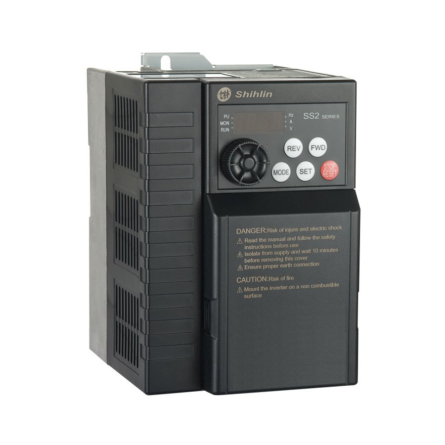
Page 12: Mechanical Dimensions
Introduction of Shihlin Inverter Introduction of Inverter 3.3 Mechanical Dimensions 3.3.1 Frame A 2×R2.5 DANGER: Risk of injure and electric shock Read the manual and follow the safety instructions before use Isolate from supply and wait 10 minutes before removing this cover Ensure proper earth connection CAUTION: Risk of fire... - Page 13 Introduction of Shihlin Inverter Introduction of Inverter 3.3.2 Frame B 43.5 2×R2.5 DANGER: Risk of injure and electric shock Read the manual and follow the safety instructions before use Isolate from supply and wait 10 minutes before removing this cover Ensure proper earth connection CAUTION: Risk of fire...
-
Page 14: Name Of Each Part
Introduction of Shihlin Inverter Introduction of Inverter 3.4 Name of Each Part 3.4.1 Nameplate and model Model Suitable motor :0.4KW Rated input Rated output (Rated output current 、 Rated output voltage 、 Rated output frequency) Software version Serial NO. 3.4.2 Names of the components mounting hole BASEBOARD LED screen... - Page 15 Introduction of Shihlin Inverter Introduction of Inverter the main circuit 2. The enlarged figure of terminal block is as follows:...
-
Page 16: Installation And Wiring
Introduction of Shihlin Inverter Introduction of Inverter 3.5 Installation and Wiring 3.5.1 Transport Take the pedestal when carrying and don’t only take the cover or any part of the inverter, otherwise it may drop down. 3.5.2 Stockpile This product before installing must be placed in the packaging. If it is not in use, change the frequency to meet the company's warranty scope and future maintenance. - Page 17 Introduction of Shihlin Inverter Introduction of Inverter Commonly signal wire (weak) and power wire (heavy) are in control cabinet, for the inverter, power wire is divided into input line and output line. Signal wire is easily interfered by power wire, so that causing the misoperation of the device.
- Page 18 Introduction of Shihlin Inverter Introduction of Inverter 3.5.4 Installation notice 1. 1. Please install in an upright direction. 2. Clear the surroundings when installing. 3. The ambient temperature shall not exceed the 4. Install inverters in a protection case correctly. permissible value.
- Page 19 Introduction of Shihlin Inverter Introduction of Inverter Orbit determination installation: 1. Orbit determination installation 2. Orbit determination removes 3. Orbit determination installation side by side...
- Page 20 Introduction of Shihlin Inverter Introduction of Inverter Installation with screws: 2-M4×8 Note: 1. Please choose the screw size M4. 2. Carry out the installation, wire arrangement, dismounting and maintenance by qualified electrical professional personnel. 3. Follow the installation notice. In case the installation notice has not been fully complied with and damage of the inverter or dangerous accidence thus be resulted in, our company will not undertake any legal responsibility.
- Page 21 Introduction of Shihlin Inverter Introduction of Inverter 3.5.5 System wire arrangement...
- Page 22 Introduction of Shihlin Inverter Introduction of Inverter 3.5.6 Terminal wire arrangement ===== Note: ============================================================== 1. For the usage of the external thermal relay, please refer to P.80~P.84, P.86 in Chapter 5. 2. Make sure not to short circuit the PC and SD. 3.
- Page 23 Introduction of Shihlin Inverter Introduction of Inverter Note: 1. For multi-function control terminals, please refer to P.80~P.84, P.86, and for multi-function output terminals, please refer to P.40 in Chapter 5. 2. For SS2-TYPE series inverters, the multi-function control terminals have both the sink input mode and the source input mode.
- Page 24 Introduction of Shihlin Inverter Introduction of Inverter If the source input mode is selected, the function of the multi-function control; terminal is active when it is shorted with PC or connected with the external PLC. At this mode, the current flows into the corresponding terminal when it is ‘on’.
- Page 25 Introduction of Shihlin Inverter Introduction of Inverter Note: 1. For SS2-TYPE series of inverters, brake resistor is not included. For information related to braking resistor, please refer to 3.6.3. 2. For information related to regenerative voltage, please refer to P.30 in Chapter 5. 3.
- Page 26 Introduction of Shihlin Inverter Introduction of Inverter Control terminals Terminal Function Terminal Type Remarks and Function Description Name Name Optional Optional These terminals are multi-function control terminals Optional (SINK/SOURCE mode switchable). For detailed descriptions, please refer to P.80~P.84, P.86 in Optional Chapter 5.
- Page 27 Introduction of Shihlin Inverter Introduction of Inverter 3.5.7 Wiring precautions Main circuit wiring: 1. Do not connect the power supply wires to the inverter output terminals U/T1-V/T2-W/T3 that are designed for connecting motors; otherwise, the inverter may be damaged. 2. Please do not mount filtering capacitors, surge absorbers and electromagnetic contactors at the output end of the inverter.
- Page 28 Introduction of Shihlin Inverter Introduction of Inverter 5. Wiring installation First insert slotted screwdriver with terminal blocks, pressing terminal blocks down, and then insert the electric wires. 6. Wiring demounting First insert slotted screwdriver with terminal blocks, and pressing terminal blocks down, and then pull out the wire.
-
Page 29: Selection Of Peripheral Equipments
Introduction of Shihlin Inverter Introduction of Inverter 3.6 Selection of Peripheral Equipments 3.6.1 No-fuse switch Power Source Applicable NFB/MCCB Applicable MC Inverter Type Motor Capacity Capacity Type (Shihlin) Type (Shihlin) SS2-021-0.4K 220V 0.5HP 1.5kVA BM30SN3P5A S-P11 SS2-021-0.75K 220V 1HP 2.5kVA BM30SN3P10A S-P11 SS2-021-1.5K... - Page 30 Introduction of Shihlin Inverter Introduction of Inverter 3.6.2 Power cable specification/pressing connection terminals specification Power Cable Specification Pressing connection terminal (PVC cables standard) specification (used by power cables) Power supply terminal Loading terminal Inverter Type (R/L1- S/L2- T/L3) (U/T1-V/T2-W/T3) Power supply Loading Crimping Tightening...
- Page 31 Introduction of Shihlin Inverter Introduction of Inverter 3.6.3 Brake resistors Inverter Type Brake Resistor Specification Inverter Type Brake Resistor Specification SS2-021-0.4K 100W 220Ω SS2-023-3.7K 400W 40Ω SS2-021-0.75K 150W 120Ω SS2-043-0.4K 80W 1000Ω SS2-021-1.5K 300W 60Ω SS2-043-0.75K 100W 800Ω SS2-021-2.2K 300W 60Ω...
- Page 32 Introduction of Shihlin Inverter Introduction of Inverter 3.6.5 Zero-phase reactor Motor Capacity Recommended Wire Inverter Type Qty. Wiring Method Size (mm 0.75 0.5-5.5 220V Diagram A Single- phase 3.5-5.5 0.75 0.5-5.5 220V Diagram A Three- phase 3.5-5.5 0.75 0.5-5.5 440V Diagram A Three-phase 3.5-5.5...
- Page 33 Introduction of Shihlin Inverter Introduction of Inverter 3.6.6 Input/output reactor Input AC Line Reactor 220V,50/60Hz,Three-phase Rated Amps of 2% Impedance Reactor Types 4% Impedance Reactor Types Inverter ACL-0005-EISC-E3M8 ACL-0005-EISC-E5M6 0.75 ACL-0005-EISC-E3M8 ACL-0005-EISC-E5M6 ACL-0010-EISC-E1M5 ACL-0010-EISC-E2M8 ACL-0015-EISC-E1M0 ACL-0015-EISC-E1M9 17.5 ACL-0020-EISC-EM75 ACL-0020-EISC-E1M4 440V,50/60Hz,Three-phase Rated Amps of 2% Impedance Reactor Types 4% Impedance Reactor Types...
- Page 34 Introduction of Shihlin Inverter Introduction of Inverter 220V,50/60Hz,Three-phase Rated Amps of 1% Impedance Reactor Types 2% Impedance Reactor Types Inverter OCL-0005-EISC-E1M4 OCL-0005-EISC-E2M8 0.75 OCL-0005-EISC-E1M4 OCL-0005-EISC-E2M8 OCL-0010-EISC-EM70 OCL-0010-EISC- E1M4 OCL -0015-EISC-EM47 OCL -0015-EISC-EM93 17.5 OCL -0020-EISC-EM35 OCL -0020-EISC-EM70 440V,50/60Hz,Three-phase Rated Amps of 1% Impedance Reactor Types 2% Impedance Reactor Types Inverter...
-
Page 35: Primary Operation
Primary Operation Primary Operation 4. Primary Operation 4.1 Operation Modes of the Inverter ● The operation modes are related to the reference source of the target frequency and the signal source of the motor starting. Shihlin SS2-TYPE inverter has a total of 9 kinds of operation modes, namely, PU mode, JOG mode, external mode, communication mode, combined mode 1, combined mode 2, combined mode 3, combined mode 4 and combined mode 5. - Page 36 Primary Operation Primary Operation Related Operation Reference Source of Target Signal Source of Motor Values Remarks Parameters Mode Frequency Starting Combined mode 1 operation panel External terminals ( ) External voltage/current Combined signal, combination of Press the key mode 2 multi-speed stage levels (...
- Page 37 Primary Operation Primary Operation 4.1.1 The flow chart for transferring operation modes with operation panel Note: 1. At the PU mode, the indicating lamp in the operation panel will be lit up. 2. At the external mode, the display screen will display 3.
- Page 38 Primary Operation Primary Operation Note: 1. For detailed operating flow at monitoring mode, please refer to Section 4.1.3. 2. For detailed operating flow at frequency setting mode, please refer to Section 4.1.4. 3. For detailed operating flow at parameter setting mode, please refer to Section 4.1.5. 4.
- Page 39 Primary Operation Primary Operation 4.1.5 Operating flow chart for the parameter setting mode with operation panel The third bit flashes The second bit flashes The first bit flashes Enter the next Read new set value Read previous set value setting mode Set value written and it flashes Note: At the parameter setting mode, both the indicating lamp of...
-
Page 40: Basic Operation Procedures For Different Modes
Primary Operation Primary Operation 4.2 Basic Operation Procedures for Different Modes 4.2.1 Basic operation procedures for the PU mode (P.79=0 or 1 ) Steps Description • Change the operation mode to PU mode, and the indicating lamp of will be lit up. Note: 1. - Page 41 Primary Operation Primary Operation Steps Description • Turn on STF or STR To run the motor. • At this time, the indicating lamp of will flicker, indicating that the motor is running. Note: 1. Please refer to P.78 and multi-function terminal P.80~P.84, P.86 in Chapter 5 for advanced setting for starting terminals STF and STR.
- Page 42 Primary Operation Primary Operation 4.2.5 Basic operation procedure for combined mode 1 ( , P.79=4 ) Steps Description • At the combined mode 1, the indicating lamp of will flicker. Note: Please refer to Section 4.1 for selecting and switching the operation modes, •...
- Page 43 Primary Operation Primary Operation 4.2.7 Basic operation procedures for combined mode 3 ( , P.79=6) ● Target frequency is determined by communication. hen M0, M1, M2 and REX are ‘On’, the target frequency will be determined by the combination of multi-speed stage levels (Please refer to P.4~P.6, P.80~P.84, P.86).
-
Page 44: Operation
Primary Operation Primary Operation 4.3 Operation 4.3.1 Checking and preparation before operation Examine the following aspects before the operation: 1. Check the wiring. Make sure that the AC motor driver output terminals (U/T1-V/T2-W/T3) are not connected to the power and the grounding terminals are well grounded. 2. - Page 45 Primary Operation Primary Operation 2. Pick up a switch between STF and SD or STR and SD. 3. Pick up a potentiometer among 2-5-10 or provide 0~5V DC between 2 and 5. 4. Adjust the potentiometer to a minimum value between or 0 and 5V DC (under 1V). 5.
-
Page 46: Parameter Description
Parameter Description Parameter Description 5. Parameter Description (1) Adjusting the output torque of motor (current) 5.1 Torque Boost (P.0, P.46) V/F ........................45 5.11 Stall Prevention (P.22, P.23, P.66) ....................... 56 5.40 Slip Compensation Coefficient (P.89) V/F ..................108 5.47 Zero-speed Function (P.151~P.152) V/F .................... - Page 47 Parameter Description Parameter Description 5.29 Zero Current Detection (P.62, P.63) ......................97 5.37 Multi-function Terminals Function Selection (P.80~P.84, P.86) ............... 102 5.38 Multi-Function Control-Terminal Input Positive/Negative Logic (P.87)..........107 5.39 Multi-Function Output Terminal Positive/Negative Logic(P.88) ............. 108 5.49 External Terminals Filter Adjusting Function (P.157) ................115 5.67 Maintenance Alarm Function (P.261) .......................
- Page 48 Parameter Description Parameter Description (16) The selection of the running mode and the operation site 5.17 Communication Running and Speed Command(P.35) ................79 5.36 Operation Mode Selection (P.79) ......................101 5.50 External Terminal Power Enable Function (P.158) ................... 116 (17) The communicational running and setting 5.16 Communication Function (P.32, P.33, P.36, P.48~P.53, P.153~P.154) ............
-
Page 49: Torque Boost (P.0, P.46) V/F
Parameter Description Parameter Description 5.1 Torque Boost (P.0, P.46) P.0 “Torque boost” P.46 “The second torque boost” ● For an inverter controlled by the V/F mode, the starting torque is usually inadequate when starting the motor because the output voltage of the inverter is inadequate. In this case, improve the output voltage by setting up a proper torque boost (P.0) to obtain a better starting torque. -
Page 50: Range Of The Output Frequency
Parameter Description Parameter Description 5.2 Range of the Output Frequency (P.1, P.2, P.18) P.1 “Maximum frequency” P.2 “Minimum frequency” P.18 “High-speed maximum frequency” ● The upper limit and the lower limit of the output frequency can be restricted. Parameter Factory Setting Setting Range Remarks 120Hz... -
Page 51: Base Frequency And Base Frequency Voltage
Parameter Description Parameter Description 5.3 Base Frequency and Base Frequency Voltage (P.3, P.19, P.47) P.3 “Base frequency” P.19 “Base frequency voltage” P.47 “The second base frequency” ● The maximum output voltage of the inverter is referred to as “Base frequency voltage”. ●... -
Page 52: Multi-Speed
Parameter Description Parameter Description 5.4 Multi-speed (P.4~P.6, P.24~P.27, P.142~P.149) P.4 “Speed 1(high speed)” P.5 “Speed 2(medium speed)” P.6 “Speed 3 (low speed)” P.24~P.27 “Speed 4 to 7” P.142~P.149 “Speed 8 to 15” Parameter Factory Setting Setting Range Remarks 60Hz 0~650Hz 30Hz 0~650Hz 10Hz... -
Page 53: Acceleration/Deceleration Time
Parameter Description Parameter Description • Provided that the values of P.24~P.27 and P.142~P.149 are all defaulted, the ‘3-speed operation’ is active. In this case, the target frequency can be set as follows (the priority for the terminals is RL > RH): >... - Page 54 Parameter Description Parameter Description Parameter Factory Setting Setting Range Remarks 5s(3.7KW and below) 0~360s When P.21=0 10s(5.5KW) 0~3600s When P.21=1 5s(3.7KW and below) 0~360s When P.21=0 10s(5.5KW) 0~3600s When P.21=1 50Hz When P.189=1 1~650Hz 60Hz When P.189=0 Minimum setting increment:0.01s 0, 1 Minimum setting increment:0.1s 0~360s...
-
Page 55: Electronic Thermal Relay Capacity
Parameter Description Parameter Description 5.6 Electronic Thermal Relay Capacity (P.9) P.9 “Electronic thermal relay capacity” ● To simulate a thermal relay to prevent the motor from overheating, the electronic thermal relay employs a built-in program. Parameter Factory Setting Setting Range Remarks 0~500A <Setting>... -
Page 56: Starting Frequency
Parameter Description Parameter Description <Setting> • The stop signal (please refer to Chapter 4 for the primary operation) will cause a gradual decrease of the output frequency of the inverter. In case the output frequency reaches the DC injection brake operation frequency (P.10), the DC injection brake will be activated. -
Page 57: Load Pattern Selection
Parameter Description Parameter Description 5.9 Load Pattern Selection (P.14, P.98, P.99, P.162~P.169) P.14 “Load pattern selection” P.167 “Output voltage 4 of middle P.98 “Middle frequency 1” frequency” P.99 “Output voltage 1 of middle P.168 “Middle frequency 5” frequency” P.169 “Output voltage 5 of middle P.162 “Middle frequency 2”... - Page 58 Parameter Description Parameter Description <Setting> • If P.14=4, P.19=220V, P.98=5Hz and P.99=10%, the output voltage equals to P.99×P.19=10%×220V=22V when the inverter is run at 5Hz. • P.46 The Second Torque Boost is valid if RT is on. P.14=0 P.14=1 Applicable to constant torque loads Applicable to variable torque loads (conveyor belt, etc.) (fans, pumps, etc.)
- Page 59 Parameter Description Parameter Description P.14=6,7,8 P.14=9,10 P. 19 Output frequency P. 3 When P.14=6, A is 8.7%; when P.14=7, A is When P.14=9, A is 20.0%; when P.14=10, A is 10.4%; when P.14=8, A is 12.0%. 25.0%. P.14=11,12,13 When P.14=11, A is 9.3%; when P.14=12, A is 12.7%;...
-
Page 60: Jog Mode
Parameter Description Parameter Description 5.10 JOG Mode (P.15, P.16) P.15 “JOG frequency” P.16 “JOG acceleration/deceleration time” ● At the JOG mode, the output frequency is the set value of P.15, and the acceleration/deceleration time is the set value of P.16. Parameter Factory Setting Setting Range... -
Page 61: Output Frequency Filter Constant
Parameter Description Parameter Description Parameter Factory Setting Setting Range Remarks 200% 0~250% When P.23=9999, stall prevention 9999 0~200%, 9999 operation level is the set value of P.22. 50Hz When P.189=1 0~650Hz 60Hz When P.189=0 <Setting> • During the period of starting a motor or increasing the output frequency, the output current of the inverter will increase. -
Page 62: Acceleration/Deceleration Curve Selection
Parameter Description Parameter Description 5.13 Acceleration/deceleration Curve Selection (P.29, P.255~P.258) P.29 “Acceleration/deceleration curve P.258 “S pattern time at the end of selection” Deceleration” P.255 “S pattern time at the beginning of Acceleration” P.256 “S pattern time at the end of Acceleration”... - Page 63 Parameter Description Parameter Description The equation for the ascending S-shape curve between 0 and P.3 is: The equation for the ascending S-shape curve above P.3 is: t: Time f: Output frequency Note: This pattern is applicable to the mainframes of working machines. •...
- Page 64 Parameter Description Parameter Description • When P.29=3, “S pattern acceleration /deceleration curve 3” The parameters P.255, P.256, P.257 and P.258 are used to start the inverter gradually without impact. And varying degrees of S pattern acceleration/deceleration curve are adjusted by the values.
-
Page 65: Regenerative Brake
Parameter Description Parameter Description 5.14 Regenerative Brake (P.30, P.70) P.30 “Regenerative brake function selection” P.70 “Special regenerative brake duty” ● Changing the output frequency from high to low will cause the motor speed to be greater than the output frequency of the inverter due to load inertia and thereby inducing the generator effect. In this case, a high voltage will exist between the main-circuit terminals +/P and -/N and damage the inverter. -
Page 66: Communication Function
Parameter Description Parameter Description 5.16 Communication Function (P.32, P.33,P.34, P.36, P.48~P.53, P.153~P.154) P.32 “Serial communication Baud rate selection” P.33 “Communication protocol selection” P.34 “Communication EEPROM writing selection” P.36 “Inverter station number” P.48 “Data length” P.49 “STOP bit length” P.50 “Parity check selection” P.51 “CR &... - Page 67 Parameter Description Parameter Description Factory Parameter Setting Range Remarks Parameter Setting Only CR CR and LF 0~10 (Note 2) Conduct communication overtime test 0~999.8s according to the set value 9999 0~999.8s, 9999 9999: No communication overtime test 9999 (Note 3) Warn and call to stop 0, 1 No warning and keep running...
- Page 68 Parameter Description Parameter Description Steps for different communication type with or without data format: Operation Operation Write Read Out Description Reset Monitoring Command Frequency Parameter Parameter Computer sends out ① communication request to inverter Inverter Data ② Processing time Data No error responded (request...
- Page 69 Parameter Description Parameter Description ③ Data transmission from the computer to inverter; inverter’s data responses Write data ● Information Number Format Stop Character Station Number (Data no error) Error Code Stop Character Station Number (Data error) Readout data ● Information Number Format Stop Station...
- Page 70 Parameter Description Parameter Description included. *4) Unit: 0 denotes that the unit is 1; 1 denotes that the unit is 0.1; 2 denotes that the unit is 0.01; 3 denotes that the unit is 0.001. *5) Error Code: Error Error Item Communication error exception content Code Parity check: What the inverter has received is different from the initial...
- Page 71 Parameter Description Parameter Description Station Number Command Code Data Waiting Time Sum Check H0000 H30 H30 H46 H41 H30 H30 H30 H30 H44 H37 Step2. The inverter responds to the computer using format C after receiving and processing the data: Station Number H30 H30 Example 3.
- Page 72 Parameter Description Parameter Description 1) Deduct 100 from 195 and get 95. 1) The minimum unit of P.195 is 0.01, therefore the Convert 95 to hexadecimal H5F. product of 50 and 100 is 5000. Add H5F to H80 and get HDF. 2) Convert 5000 to hexadecimal H1388.
- Page 73 Parameter Description Parameter Description (2). Normal response After receiving the query from the computer, the inverter performs the requested function from the computer and return to the normal function. (3). Error response If the inverter receives an invalid function code, address, or data, it will send feedback to the computer.
- Page 74 Parameter Description Parameter Description Algorithm of LRC checksum: LRC check is relatively simple. It is at the ASCII mode for detecting messages except the beginning of the colon field and the end of the carriage return line number. It only needs to transmit the data of each byte stack, and if the result is greater than hexadecimal H100, after removal of the excess (such as: the results obtained for the hexadecimal H136, only to take H36) can be reversed then plus 1.
- Page 75 Parameter Description Parameter Description (2). Write data (H06) Address Function Initial Address Write Data Mode Start Check ASCII 2char 2char 4char 4char 2char 0D 0A >=10ms 1byte 1byte 2byte 2byte 2byte >=10ms Normal response Address Function Initial Address Write Data Mode Start Check...
- Page 76 Parameter Description Parameter Description Setting of the query information Information Content *1) Address Set the address for the information to be sent to, not able to radio communications(0 invalid) *2)Function code H08 *3)Subroutine H0000 code *4) Data If the data is 2 byte, it can be set arbitrarily. Set range from H0000 to HFFFF. (4).
- Page 77 Parameter Description Parameter Description Message Content *1) Address Set the address for the information to be sent to. *2) Function code Function code+H80 *3) Error code Set the code from the following table. List of error codes: Resource Code Meaning Remarks The inverter can not handle the code from the query Invalid function...
- Page 78 Parameter Description Parameter Description Step 2. The inverter responds to the computer after receiving and processing the data, Mode Start Address Function Initial Address Write Data Check ASCII H31H30 0D 0A >=10ms 8D 0A >=10ms Example 2.Read computer communication P.195: Step 1.
- Page 79 Parameter Description Parameter Description Step 2. After receiving and processing the data, the inverter sends feedback to the computer. Number of Read Mode Start Address Function Read Data Check Data ASCII H30 H31 H30 H33 H31 H38 …24×1 char 2char 0D 0A >=10ms …24×1 byte...
- Page 80 Parameter Description Parameter Description Shihlin Modbus Modbus Item Protocol Information Content and Functions Code Address Code H0000~H00FF b8~b15:reserved b7:Alarm occurrence b6:Frequency detection b5:Parameters to default values end. Inverter State H1001 b4:Overload b3:Frequency achieved b2:Reverse rotation b1:Forward rotation b0:Operation EEPR H1009 frequen H0000~HFDE8 H1002...
- Page 81 Parameter Description Parameter Description Shihlin Modbus Modbus Item Protocol Information Content and Functions Code Address Code Operati EEPR H1009 H06/H10 frequen H0000~HFDE8: 0~650HZ H1002 write in H5A5A H1104 Inverter H9966 H1103 parameter and See parameter recovery H06/H10 H9696 H1106 error code description table H55AA H1105...
- Page 82 Parameter Description Parameter Description Shihlin Modbus Information Content and Functions Modbus Protocol Address Item Code Code Parameter read out H00~H63 P.0~P.499; for the range and decimal H0000 point, please refer to the parameter list. Every parameter modbus address is the H01F3 band parameter...
- Page 83 Parameter Description Parameter Description ● The table of the special monitor code Information Content Unit H0000 Monitor the external terminal input port state. Note1 H0001 Monitor the external terminal output port state. Note2 H0002 Monitor the voltage which can be input across terminal 2-5. 0.01V H0003 Monitor the voltage/current which can be input across terminal 4-5.
-
Page 84: Speed Display
Parameter Description Parameter Description 5.18 Speed Display (P.37, P.259) P.37 “Speed display” P.259 “Speed unit selection” ● At the output frequency monitoring mode, the screen will display the corresponding mechanical speed. Parameter Factory Setting Setting Range Remarks Output frequency 0~5000.0r/min 0 r/min 0.1~5000.0r/min P.259=1 0~9999 r/min... -
Page 85: Voltage Signal Selection And Target Frequency
Parameter Description Parameter Description 5.19 Voltage Signal Selection and Target Frequency (P.38, P.73, P.139~P.141) P.38 “The maximum operation frequency (the target frequency is set by the input signal of terminal 2-5)” P.73 “Voltage signal selection” P.139 “Voltage signal bias” P.140 “Voltage signal gain” P.141 “Voltage signal bias direction and rotational direction setup”... - Page 86 Parameter Description Parameter Description Here are some examples: Example 1: This is the most used setting. When the inverter is at the external mode, the combined mode 2 or the combined mode 4, the frequency is set by terminal 2-5. Example 2: This example shows the effect of changing the bias.
- Page 87 Parameter Description Parameter Description Example 4: This example shows a potentiometer range between 0V and 5 V. Instead of adjusting gain as the example below, the user can set P.38 to 120Hz or P.73 to 0 to achieve the same result.
- Page 88 Parameter Description Parameter Description Example 7: In this example, the input is programmed to run a motor in both forward and reverse directions. The motor will idle when the potentiometer position is at the mid-point of the scale. Using the settings in this example to disable the external FWD and REV controls. Max output frequency 60Hz Forward direction...
-
Page 89: The Input Signal Across Terminal 4-5 And The Target Frequency
Parameter Description Parameter Description 5.20 The Input Signal across Terminal 4-5 and the Target Frequency (P.17, P.39) P.17 “Input signals across terminal 4-5 selection” P.39 “The maximum operation frequency (the target frequency is set by the input signal of terminal 4-5)” ●... -
Page 90: Multi-Function Output (P.40, P.64, P.74, P.85, P.120 And
Parameter Description Parameter Description 5.21 Multi-function Output (P.40, P.64, P.74, P.85, P.120 and P.187) P.40 “Multi-function output terminal pattern” P.64 “Pulse output selection” P.74 “10X output selection” P.85 “Function selection for multi-function relay” P.120 “Output signal delay time” P.187 “FM calibration parameter” Parameter Factory Setting Setting Range Remarks... - Page 91 Parameter Description Parameter Description Parameter function PO2 (Periodical detection): At the programmed operation mode, PO2 signal will be output at the end of each cycle. PO3 (Pause detection): At the programmed operation mode, PO3 signal will be output when the inverter pauses. BP (Inverter output): Switch between the inverter operation and commercial power-supply operation function.
- Page 92 Parameter Description Parameter Description • When P.64=1 and P74=0, the function of external terminal SO is FM function. The user can insert an electricity meter (current load: 1mA) or a frequency counter between terminal SO and SE to display the output frequency or the output currency of the inverter. •...
-
Page 93: Up-To-Frequency Sensitivity
Parameter Description Parameter Description • When P.74=5 and temporary running frequency is at 20Hz, we can detect output impulse wave between terminal SO and SE as follows: Note: 1. The multi-function output terminal is SO, When P.40=0 (the default value), it means ‘RUN’. When a different value is set, the corresponding function will change according to what is shown in the above table. -
Page 94: Output Frequency Detection
Parameter Description Parameter Description Note: In this paragraph, SU is the function name of the multi-function output terminal. Please refer to P.40 for function selection and features. About wiring, please refer to Section 3.5.6. 5.23 Output Frequency Detection (P.42, P.43) P.42 “Output frequency detection for forward rotation”... -
Page 95: Am Terminal
Parameter Description Parameter Description Parameter Factory Setting Setting Range Remarks 0~650Hz 9999 0~650Hz, 9999 9999: same as P.42 setting <Setting> • If P.42=30 and P.43=20, then a signal (FU) is output when the forward rotation output frequency exceeds 30Hz or when the reverse rotation output frequency exceeds 20Hz. •... -
Page 96: Restart Function (P.57, P.58, P.150) V/F
Parameter Description Parameter Description • When P.54=0, a voltage of 10V is output at terminal AM if the output frequency of the inverter is the set value of P.55. • When P.54=1, a voltage of 10V is output at terminal AM if the output current of the inverter is the set value of P.56. - Page 97 Parameter Description Parameter Description <Setting> • When the motor is running, the output voltage will not be constant once the driving power is interrupted. When the power is recovered, the inverter will not restart automatically if P.57=9999. If P.57=0.1~5, the motor will coast for a while (the set value of P.57), and then the inverter will restart the motor automatically.
-
Page 98: The Choice Of Locking Operation Keyboard Knob Setting
Parameter Description Parameter Description 5.26 The Choice of Locking Operation Keyboard Knob Setting (P.59) P.59” The choice of locking operation keyboard knob setting” Factor Paramet Setting Range Remarks Settin 0,1,10,11,100,101,110,111,200,201,210,211,1000,1001,1010, 1011,1100,1101,1110, 1111,1200,1201,1210,1211 • P.59 is set by the digits, and there are 4 digits in total. The meaning of each digit is as follows: P.59 = 0 0, the default value, reserved 0, the jog dial has no set function... -
Page 99: Remote Control Function Selection
Parameter Description Parameter Description 5.28 Remote Control Function Selection (P.61) P.61 “Remote setting function selection” ● If the operation box is located away from the control box, contact signals can be used to perform the continuous variable-speed operation without using analog signals at the external mode, the PU mode, the combined mode 1 or the combined mode 5. - Page 100 Parameter Description Parameter Description 2. At the remote setting, the output frequency of the inverter is: Target Frequency set by external terminals: Frequency set by RH/RM operation+external set frequency other than multi-speeds Target Frequency set by operation panel: PU set frequency + external set frequency other than multi-speeds •...
-
Page 101: Zero Current Detection
Parameter Description Parameter Description 5.29 Zero Current Detection (P.62, P.63) Related parameters P.62 “Zero current detection level” P.40 “Multi-function output P.63 “Zero current detection time” terminal pattern” P.85 “Function selection for multi-function relay” Parameter Factory Setting Setting Range Remarks 0~200%, 9999 9999: Function invalid 0.5s 0.05~60s, 9999... -
Page 102: Brake Selection
Parameter Description Parameter Description executed. A second alarm occurs successively within P.68 5 seconds is defined as continuous alarms. × The occurrence of a continuous alarm that is more frequent than the pre-defined upper limit indicates a significant malfunction. In this case, special measures should be taken manually and retry will not be executed any more. -
Page 103: Carrier Frequency
Parameter Description Parameter Description STOP pressing , and the motor will be racing. RESET • When P.71=1, it is now beeline brake. The output of the inverter will follow the STOP acceleration/deceleration curve after pressing RESET 5.32 Carrier Frequency (P.72) P.72 “Carrier frequency”... -
Page 104: Stop Or Reset Function Selection
Parameter Description Parameter Description Note: The optimum carrier frequency shall be eight times greater than the target frequency. 5.33 Stop or Reset Function Selection (P.75) P.75 “Stop or reset function selection” Parameter Factory Setting Setting Range Remarks 0, 1 <Setting> •... -
Page 105: Parameters Write Protection
Parameter Description Parameter Description 5.34 Parameters Write Protection (P.77) P.77 “Parameters write protection” Parameter Factory Setting Setting Range Remarks 0~2,4 <Setting> • If P.77=0, all parameters except P.90、P.188、P.289、P.291 can be written when the motor stops. When the motor runs, only P.4~P.6, P.24~P.27, P.54~P.56, P.77, P.131~P.138, P.142~P.149, P.161, P.190~P.199, P.223~P.225,P.230, P.232, P.288 and P.290 can be written. -
Page 106: Multi-Function Terminals Function Selection
Parameter Description Parameter Description Factory Setting Parameter Remarks Setting Range Only the combined mode 3 is valid. Only the combined mode 4 is valid. Only the combined mode 5 is valid. Please refer to Section 4.1 for details. 5.37 Multi-function Terminals Function Selection (P.80~P.84, P.86) P.80~P.84, P.86 “Multi-function terminals function selection”... - Page 107 Parameter Description Parameter Description Para- Factory Setting Terminal Value Function Name Function Description Remarks meter Setting Range When RT is on, the Please refer to characteristics are the same P.44 as the second function. 0~41 At the external mode, the target frequency is set by 43~45 P.15 and the acceleration/...
- Page 108 Parameter Description Parameter Description Para- Termi Factory Setting Value Function Name Function Description Remarks meter Setting Range At the external mode, programmed operation mode is chosen when 0~40 PO is on. , 43~45 When the alarms RES_E occur, external Reset became effective At the external mode, manually operation...
- Page 109 Parameter Description Parameter Description Para- Factory Setting Terminal Value Function Name Function Description Remarks meter Setting Range When the signal is valid, the source of 0~40 The second frequency frequency is SEC_FRE source setting enable decided 43~45 according to P.97 setting value.
- Page 110 Parameter Description Parameter Description (3) Three-wire control mode 2 (with self maintaining function):K1: STOP signal, normally closed. If it is open, the inverter will stop. K2: RNU signal, normally open, and the pulse signal are active. (4) Three-wire control mode2 (with self maintaining function):K1: STOP signal, normally close. If K1 is opened, the inverter will be stopped.
-
Page 111: Multi-Function Control-Terminal Input Positive/Negative Logic
Parameter Description Parameter Description This function is only for terminal. Near the lowest frequency or maximum frequency, output frequency precision which relative to the input signal will reduce; avoid the use of requiring a tight frequency control. 5.38 Multi-Function Control-Terminal Input Positive/Negative Logic (P.87) P.87 “Multi-Function Control-Terminal Input Positive/Negative Logic”... -
Page 112: Multi-Function Output Terminal Positive/Negative Logic
Parameter Description Parameter Description 5.39 Multi-Function Output Terminal Positive/Negative Logic(P.88) P.88 Multi-function output terminal positive/negative logic(P.88) ” “ ● The function is bits-setting, if the bit is 1, it means that the act of multi-function output terminal is negative logic; otherwise, it means that the act is positive logic. Parameters Factory Setting Setting Range... -
Page 113: Frequency Jump
Parameter Description Parameter Description The applicable motor capacity is as following table: Value (value of the two Value (value of the two capacity (kw) capacity (kw) low-order bits of P.90) low-order bits of P.90) 0.75 5.42 Frequency Jump (P.91~P.96) P.91~P.96 “Frequency jump” ●... -
Page 114: Programmed Operation Mode
Parameter Description Parameter Description 5.43 The Second Frequency Source(P.97) P.97 “The second frequency source” ●When multi-function control terminal selects the second frequency source setting enable which is valid, the frequency source is decided according to the P.97 setting value. And in this condition, it is impossible to change the operation mode. - Page 115 Parameter Description Parameter Description Parameter Factory Setting Setting Range Remarks The running time minimum increment is 1 minute. 0, 1 The running time minimum increment is 1 second. 101~108 0~6000s 0~600s When P.21=0 111~118 0~6000s When P.21=1 Parameter Factory Setting Setting Range Remarks 0: Cycle function invalid;...
- Page 116 Parameter Description Parameter Description • When the value of P.122 is 1~8, it is the initialization section of the cycle running. For example: When P.122=3, the inverter will run circularly from the third section to the eighth section after it finishes the running from the first section to the eighth section. When P.123=0, the acceleration time is determined by P.7, and the deceleration time is determined by P.8.
-
Page 117: Operation Panel Monitoring Selection
Parameter Description Parameter Description 5.45 Operation Panel Monitoring Selection (P.110) P.110 “Operation panel monitoring selection” Factory Setting Parameter Remarks Setting Range When the inverter starts, the operation panel enters the monitoring mode automatically, and the screen displays the output frequency. When the inverter starts, the screen of the operation panel displays the target frequency. -
Page 118: Zero-Speed Function (P.151~P.152) V/F
Parameter Description Parameter Description • The diagram is as follows: 5.47 Zero-speed Function (P.151~P.152) P.151 “Zero-speed control function selection” P.152 “Voltage instruction at zero-speed control” ● The user must set the value of P.13 zero when using this function. Parameter Factory Setting Setting Range Remarks There are no output at zero speed... -
Page 119: External Terminals Filter Adjusting Function
Parameter Description Parameter Description alarm (set the value to 12), the inverter will send out OL2 signal; If the multi-function output terminal SO-SE (P.40) or the multi-function relay ABC (P.85) are set as over load alarm (set the value to 3), only when P.260=1, will inverter send out OL signal. -
Page 120: External Terminal Power Enable Function
Parameter Description Parameter Description 5.50 External Terminal Power Enable Function (P.158) P.158 “External terminal power enable” Parameter Factory Setting Setting Range • If P.158=1, select the external terminal power enabling function. At this situation, if the multi-function terminal function is STF, STR, RUN or MPO and the opposite terminal is connected before the power is on, then the inverter will not run. -
Page 121: Pid Control
Parameter Description Parameter Description Factory Setting Parameter Remarks Setting Range The current feedback pressure of the constant pressure system. The current operation frequency. The current electronic thermal accumulation rate. The value of the input signal across terminal 2-5 (V). The value of the input signal across terminal 4-5 (mA/V). The output power(kW) Reserved 0~13,... - Page 122 Parameter Description Parameter Description Please pay attention to the Gain setting during the process of PID Gain setting for it is possible that the output current can not be limited absolutely. ● Under PID control, the output frequency is also limited between the maximum frequency and the minimum frequency.
- Page 123 Parameter Description Parameter Description Factory Setting Parameter Remarks Setting Range 0~100% 0~255s 0~100% 40Hz 0~120Hz P.189=1 When the deviation value accumulated with the integral 50 Hz 0~120Hz time, an upper limit for deviation accumulation should 60Hz P.189=0 be set. When the feedback pressure satisfies the deviation value for stopping the machine and the set time (in seconds) for stopping 0.5Hz 0~10Hz...
- Page 124 Parameter Description Parameter Description 2. When the feedback signal need to be revised by the user: Please adjust the feedback signal to a certain value and then calculate the proportion of the value to the feedback range, then write the proportion value into P.223. After that, adjust the feedback signal to a new value and then calculate the proportion of the value to the feedback range, then write the proportion value into P.224.
- Page 125 Parameter Description Parameter Description • If P.178=0, the values of P.179, P.180 and P.181 are invalid. If the value of P.178 is not 0, PID sleep function is selected. When the absolute value of feedback value subtract the target feedback is lower than the sleep detect deviation and continue sleep detect duration time P.179, the output frequency will be diminished gradually by the inverter.
-
Page 126: Terminal Disconnection Handling
Parameter Description Parameter Description (2)Target and feedback do not become equal ---Decrease Integration time (K =P.173) become equal after unstable vibration ---Increase Integration time (K =P.173) (3)Even after increasing K , response is still slow ---Increase D-gain (K =P.174) It is still unstable ---Decrease D-gain (K =P.174) Note: When external 4-5 analog signal is given as pressure, please refer to the parameter P.17;... -
Page 127: Firmware Version
Parameter Description Parameter Description <Setting> • By external analog signal input terminals on the function of setting frequency multiplier effects. • If many inverters operation proportionally, take advantage of this function on the instructions of the master inverter to the salve inverter for fine-tuning more effective. •... -
Page 128: Factory Setting Function
Parameter Description Parameter Description 5.57 Factory Setting Function (P.189) P.189 “Factory setting function” Parameter Factory Setting Setting Range Remarks Apply to the 60Hz system 0, 1 Apply to the 50Hz system ● The user can select 50Hz or 60Hz frequency system as factory setting according to power supply frequency and motor default frequency. -
Page 129: Input Signal Across Terminal 2-5
Parameter Description Parameter Description 5.58 Input Signal across Terminal 2-5 (P.192~P.195) P.192 “2-5 terminal minimum input voltage” P.193 “2-5 terminal maximum input voltage” P.194 “Frequency corresponds to the minimum input voltage of terminal 2-5” P.195 “Frequency corresponds to the maximum input voltage of terminal 2-5” Parameter Factory Setting Setting Range... -
Page 130: Input Signal Across Terminal 4-5
Parameter Description Parameter Description 5.59 Input Signal across Terminal 4-5 (P.196~P.199) P.196 “Frequency corresponds to the minimum input current/voltage across terminal 4-5” P.197 “Frequency corresponds to the maximum input current/voltage across terminal 4-5 P.198 “Minimum input current/voltage across terminal 4-5” P.199 “Maximum input current/voltage across terminal 4-5”... -
Page 131: The Paver Function
Parameter Description Parameter Description 5.60 The Paver Function (P.226~P.228) P.226 “The paver function selection” P.227 “The limit time of positive rotation” P.228 “The limit time of reverse rotation” Factory Setting Parameter Remarks Setting Range 0, 1 The paver function is valid when 1 is set and invalid when 0 is set. The inverter will decelerate and stop when the inverter keep 0~3600s positive running for more than the setting time of P.227. -
Page 132: Backlash Compensation And Acceleration/Deceleration Interrupted For Waiting Function
Parameter Description Parameter Description • To avoid a series of dangerous conditions caused by the broken travel switch, the one-way running time which is the limit time of positive and reverse rotation. The two travel switches are not allowed to close in the meantime, or the system will stop. The diagram of operation flow 5.61 Backlash Compensation and Acceleration/Deceleration Interrupted for Waiting Function (P.229~P.233) - Page 133 Parameter Description Parameter Description increase or regenerative status. To avoid backlash, temporarily stop the acceleration/deceleration. Set the acceleration/deceleration stopping frequency and time in P.229 to P.233. Note: When setting up backlash compensation, acceleration /deceleration time only in part time longer. ●Acceleration/deceleration interrupted for waiting function If P.229=2 and start the acceleration/deceleration interrupted for waiting function, when accelerate to the frequency setted by P.230, it will keep the frequency for some time setted by P.231, and then...
-
Page 134: Triangular Wave Function (P.234~P.239) V/F
Parameter Description Parameter Description 5.62 Triangular Wave Function (P.234~P.239) P.234 “Triangular wave function selection” P.235 “Maximum amplitude” P.236 “Amplitude compensation for deceleration” P.237 “Amplitude compensation for acceleration” P.238 “Amplitude acceleration time” P.239 “Amplitude deceleration time” Parameter Factory Setting Setting Range Remarks 0~25% 0~50%... -
Page 135: Auxiliary Frequency Function
Parameter Description Parameter Description 5.63 Auxiliary Frequency Function (P.240) P.240 “Auxiliary frequency function selection” Parameter Factory Setting Setting Range Remarks <Setting> • When the value of P.240 is 0, auxiliary frequency function is not selected. • When the value of P.240 is 1, operation frequency = basic frequency + auxiliary frequency (2-5), •... -
Page 136: Options For Stopping The Cooling Fan
Parameter Description Parameter Description 5.65 Options for Stopping the Cooling Fan (P.245) P.245 “Cooling fan operation selection” Parameter Factory setting Setting range Remarks <Setting> • When P.245=0, the fan will be turned on by the RUN signal. The fan will be turned off 30 seconds after the inverter stops. -
Page 137: Commercial Power Supply Frequency Operation Function (P.247~P.250) V/F
Parameter Description Parameter Description 5.66 Commercial Power Supply Frequency Operation Function (P.247~P.250) P.247 “MC switchover interlock time” P.248 “Start waiting time” P.249 “Automatic switchover frequency from inverter to commercial power supply frequency” P.250 “Automatic switchover frequency range from commercial power supply to inverter”... - Page 138 Parameter Description Parameter Description Please pay attention to the capacity of the output terminals. The terminals are used according to the different settings for P.40 and P.85 (output terminal function selection).When the output terminal function selects 10, connect the relay driving the commercial power-supply operation. When the output terminal function selects 9, connect the relay driving the inverter operation.
- Page 139 Parameter Description Parameter Description 2. Action sequences with the automatic switchover sequence (P.249≠9999, P.250=9999). 3. Action sequences with the automatic switchover sequence series (P.249≠9999, P.250 ≠ 9999). During the automatic switchover, A: P.247 MC Switchover interlocking time; B: P.248 starting waiting time;...
-
Page 140: Maintenance Alarm Function
Parameter Description Parameter Description 5.67 Maintenance Alarm Function (P.261) P.261 “Maintenance Alarm Time” ● When Multi-function output terminal (P.40, P.85) equals 18, maintenance alarm is detecting. It means that when the inverter runs for the days that reach the parameter P.261 set value of maintenance alarm time, the multi-function terminal SO-SE or multi-function relay will send out signal. -
Page 141: Short Circuit Protection Function
Parameter Description Parameter Description 5.69 Short Circuit Protection Function (P.287) P.287 “Short circuit protection function selection” Parameter Factory setting Setting range Remarks <Setting> • Set P.287 to 0 to cancel the output end short-circuits protection function. • When P.287 is set to 1, if the output end is short, the operation panel will display the “SCP” abnormal alarm and the inverter will stop the output. -
Page 142: Accumulative Motor Operation Time Function
Parameter Description Parameter Description If both P.288 and P.290 are 0, P.289 and P.291 will be displayed as 0. Both P.289 and P.291 are read-only parameters. Abnormal code corresponded alarm condition: Abnormal Alarm Abnormal Alarm Abnormal Alarm Abnormal Alarm Number Code Number Code... -
Page 143: Motor Control Mode (P.300 And
Parameter Description Parameter Description successful. Use P.295 to set the password. Enter the initial password into P.294 to decrypt the parameter password and to modify or to set up various parameters. • P.295 is the parameter for setting up the password. The password has to be greater than 1. Once the password setup is completed, P.295 will display 1. - Page 144 Parameter Description Parameter Description • Procedures for motor parameter auto-tuning are presented below: • If you need real sensorless vector control, you should set P.300 to 3. Note: 1.The motor capacity has to be at the same level or one level below of the level of the capacity of the inverter. 2.
-
Page 145: Motor Parameter
Parameter Description Parameter Description 5.74 Motor Parameter (P.302~P.309) P.302 “Motor rated power” P.306 “Motor rated current” P.303 “Motor poles” P.307 “Motor rated rotation speed” P.304 “Motor rated voltage” P.308 “Motor excitation current” P.305 “Motor rated frequency” P.309 “Stator resistance” Parameter Factory setting Setting range Remarks... -
Page 146: Sliding Compensation Gain
Parameter Description Parameter Description 5.75 Sliding Compensation Gain (P.320) P320” Sliding compensation gain” Parameter Factory setting Setting range Remarks 0~200% < > Setting ● P320 is used to set sliding compensation gain coefficient. The bigger the value is set, the bigger the sliding compensation is. -
Page 147: Alarm History Clear
Parameter Description Parameter Description Note: 1. If the version of the inverter is updated, pick inverter parameters of the lower version inverter among inverters of different versions for parameter copying. 2. Parameters cannot be copied between inverters of different series. 3. -
Page 148: Restoration Of The Parameters To The Default Values (P.998 And
Parameter Description Parameter Description 5.80 Restoration of the Parameters to the Default Values (P.998 and P.999) P.998 “Restoring all parameters to default values” P.999 “Restoring some parameters to default values” ● Once P.998 is read-out (after the read-out, the screen will display ) and rewritten-in, all the parameters will be restored to the default values except P.21, P.188, P.189, P.292 and P.293. -
Page 149: Inspection And Maintenance
Inspection and Maintenance Inspection and Maintenance 6. Inspection and Maintenance In order to avoid the malfunction and security problems resulting from aging of the devices which is caused by environmental factors such as temperature, oil fog, dust, vibration, humidity and etc., ‘daily inspection’... -
Page 150: Regular Replacement For Some Components
Inspection and Maintenance Inspection and Maintenance 6.3 Regular Replacement for Some Components The corresponding Items period for Description replacement For the axle of a fan, the standard lifetime is about 10~35 Cooling fan 2 years thousand hours. With reference to the time of 24 hours one day, it is sure that the fan should be replaced every 2 years. -
Page 151: Igbt Module Test
Inspection and Maintenance Inspection and Maintenance 6.6 IGBT Module Test Before check, first dismount the external wires for the main-circuit terminals. Then, set your multi-meter to the ohm-testing position. Positive Negative Normal Positive Negative Normal voltage voltage result voltage voltage result R/L1 Conducting... -
Page 152: Appendix 1 Parameter List
Appendix 1 Parameter list Parameter List Appendix 1 Parameter list Parameter Minimum User setting Reference Name Setting range Default value number setting unit value page Torque boost 0~30% 0.1% (Note) Maximum frequency 0~120Hz 0.01Hz 120Hz Minimum frequency 0~120Hz 0.01Hz 50Hz/60Hz Base frequency 0~650Hz 0.01Hz... - Page 153 Appendix 1 Parameter list Parameter List Parameter Minimum User setting Reference Name Setting range Default value number setting unit value page P.19 Base frequency voltage 0~1000V, 9999 0.1V 9999 Acceleration/deceleration 50Hz/60Hz P.20 1~650Hz 0.01Hz reference frequency (Note) Acceleration/deceleration P.21 time increments Stall prevention operation P.22 0~250%...
- Page 154 Appendix 1 Parameter list Parameter List Parameter Minimum User setting Reference Name Setting range Default value number setting unit value page The maximum operation frequency (the target 50Hz/60Hz P.38 frequency is set by the 1~650Hz 0.01Hz (Note) input signal of terminal 2-5) The maximum operation frequency (the target...
- Page 155 Appendix 1 Parameter list Parameter List User Parameter Minimum Referenc Name Setting range Default value setting number setting unit e page value Number of communication P.52 0~10 reties Communication check time P.53 0~999.8s, 9999 0.1s 9999 interval AM terminal function P.54 selection 50Hz/60Hz...
- Page 156 Appendix 1 Parameter list Parameter List User Parameter Minimum Reference Name Setting range Default value setting number setting unit page value Retry accumulation time P.69 at alarm Special regenerative brake P.70 0~30% 0.1% duty Idling braking and linear P.71 0, 1 braking selection P.72 Carrier frequency...
- Page 157 Appendix 1 Parameter list Parameter List User Parameter Minimum Reference Name Setting range Default value setting number setting unit page value Multi-Function Control P.87 -Terminal Input 0~63 P107 Positive/Negative Logic Multi-function output P.88 terminal positive/negative P108 logic Slip compensation P.89 0~10 P108 coefficient...
- Page 158 Appendix 1 Parameter list Parameter List Parameter Minimum User setting Reference Name Setting range Default value number setting unit value page Runtime of section 5 in P.105 0~6000s 0.1s P110 programmed operation mode Runtime of section 6 in P.106 0~6000s 0.1s P110 programmed operation mode...
- Page 159 Appendix 1 Parameter list Parameter List Parameter Minimum User setting Reference Name Setting range Default value number setting unit value page Acceleration/deceleration P.123 0, 1 P110 time setting selection P.131 Frequency of section 1 0~650Hz 0.01Hz P110 P.132 Frequency of section 2 0~650Hz 0.01Hz P110...
- Page 160 Appendix 1 Parameter list Parameter List Parameter Minimum User setting Reference Name Setting range Default value number setting unit value page Modbus communication data P.154 format P.155 Over torque detection level 0~200% 0.1% P114 P.156 Over torque detection time 0~60s 0.1s P114 External terminals filter...
- Page 161 Appendix 1 Parameter list Parameter List Parameter Minimum User setting Reference Name Setting range Default value number setting unit value page P.175 Abnormal deviation level 0~100% 0.1% P117 P.176 Exception duration time 0~600s 0.1s P117 P.177 Exception handling mode 0, 1,2 P117 P.178 Sleep detects deviation...
- Page 162 Appendix 1 Parameter list Parameter List Parameter Minimum User setting Reference Name Setting range Default value number setting unit value page Frequency corresponds to the P.196 minimum input current/voltage 0~60Hz 0.01Hz P126 across terminal 4-5 Frequency corresponds to the 50Hz/60Hz P.197 maximum input current /voltage 0~650Hz...
- Page 163 Appendix 1 Parameter list Parameter List Parameter Minimum User setting Reference Name Setting range Default value number setting unit value page Amplitude compensation for P.236 0~50% 0.1% P130 deceleration Amplitude compensation for P.237 0~50% 0.1% P130 acceleration 0~360s P.238 Amplitude acceleration time 0.01 s/0.1s 10 s P130...
- Page 164 Appendix 1 Parameter list Parameter List User Parameter Minimum Reference Name Setting range Default value setting number setting unit page value S pattern time at the end of P.258 0~25s,9999 9999 0.01s/0.1s deceleration P.259 Speed unit selection 0, 1 P.260 Over torque detection selection 0, 1 P114...
- Page 165 Appendix 1 Parameter list Parameter List Parameter Setting Minimum User setting Reference Name Default value number range setting unit value page P.308 Motor excitation current 0~500A 0.01 A Horsepower-based P141 P.309 Stator resistance 0~99.98Ω 1Ω Horsepower-based P141 P.320 Sliding compensation gain 0~200% P142 Torque compensation filter...
-
Page 166: Appendix 2 Alarm Code List
Appendix 2 Alarm Code List Alarm Code Appendix 2 Alarm Code List Screen Code Cause Troubleshooting Display 1. Under-voltage for power supply 1. Provide a normal power supply 2. The RES is ‘on’ 2. Shut off RES 3. Bad connection between 3. - Page 167 Appendix 2 Alarm Code List Alarm Code Code Screen Display Cause Troubleshooting Over-voltage Over-voltage between Terminal Please refer to OV1, OV2. during P and Terminal N deceleration Avoid the inverter long timely The IGBT The IGBT module thermal operating under overload module is accumulating relay acts condition...
- Page 168 Appendix 2 Alarm Code List Alarm Code Code Screen Display Cause Troubleshooting 1. Exchange a larger capacity inverter and motor. 2. Check the value which setting 1. The capacitor of inverter of PID feel-back signal Gain, and motor is not enough. setting the value again 2.
-
Page 169: Appendix 3 Warning Code List
Appendix 3 Warning Code List Warning Code Appendix 3 Warning Code List Code Screen Display Cause Troubleshooting When the output current is larger than Stall prevention 1. Check if the values of operation level, the three lights P.22, P.23, and P.66 on the left side of the screen are proper. -
Page 170: Appendix 4 Troubles And Solutions
Appendix 4 Troubles and Solutions Troubles and Solutions Appendix 4 Troubles and Solutions Troubles Check points • Check whether the power supply voltage between Terminals R/L1, S/L2 and T/L3 is normal. Main circuit • Check whether the Power light is on. •... -
Page 171: Appendix 5 Optional Equipment
Appendix 5 Optional Equipment Optional Equipment Appendix 5 Optional Equipment Operation panel, operation panel installation dimensions and transmission cable: 1. DU06 operation panel 42 . 40 00 7 2. 0 000 Description on the ordering code: Model Name LNKDU06 DU06 operation panel 2. - Page 172 Appendix 5 Optional Equipment Optional Equipment 4. Snap-fit installation of DU06: <Snap-fit installation: panel cutting dimension drawing> 68.6 Suitable for 2mm Suitable for 1.2mm panel thickness panel thickness Cutout Area Cutout Area 5. CBL: Transmission cable used with the above operation panel Description on the ordering code: Model Name...
-
Page 173: Appendix 6 European Specification Compatibility Description
Appendix 6 European Specification Compatibility Description Specification Description Appendix 6 European Specification Compatibility Description This inverter qualifies the CE label. Specifications: Low Voltage Directive 2014/35/EU & Electromagnetic Compatibility Directive 2014/30/EU. 1. Electromagnetic compatibility command (EMC): (1). EMC compatibility description: For system integration, inverter is not a functionally independent device unit. It is usually a unit in the control box. - Page 174 Appendix 6 European Specification Compatibility Description Specification Description CE Certification Statement...
- Page 175 Appendix 6 European Specification Compatibility Description Specification Description...
-
Page 176: Revision Record
Revision Record Revision Record Revision Record Edition of the Published Date Revision Content Manual December,2011 V1.00 First Edition V1.01 1. Unifying names of some parameters October, 2012 (Applicable for V0.30 2. Amending some mistakes of the instruction manual or above firmware) Addition 1.
Need help?
Do you have a question about the SS2 Series and is the answer not in the manual?
Questions and answers