
Related Manuals for Amsco 400 Series


Summary of Contents for Amsco 400 Series
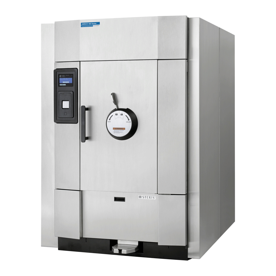
- Page 1 OPERATOR MANUAL AMSCO ® 400 Series Medium Steam Sterilizers 26"x 37.5" (660 x 953 mm) • Prevacuum Rev. AC 129394068...
- Page 3 Indications for Use ® The AMSCO 400 Series Medium Steam Sterilizer is designed for sterilization of heat- and moisture-stable materials used in healthcare facilities. The sterilizer is available in a prevacuum configuration designed for sterilization of heat and moisture-stable materials. The Prevacuum sterilizer is equipped with Prevacuum, Gravity, Leak Test and Dart (Bowie-Dick) cycles.
- Page 4 The AMSCO 400 Series Prevacuum Medium Steam Sterilizers 26 x 37.5" (660 x 953mm) are equipped with the following factory programmed sterilization cycles and cycle values (Table Table 1. Factory Default Cycles for AMSCO 400 Series 36 H, 48 H, 60 H, 36 SL, 48 SL and 60 SL Sterilizers Sterilize Sterilize...
- Page 5 Maximum Loads by Sterilizer Chamber Size Table 3. Liquid Cycle Only: Number Wrapped Fabric Model Number Chamber Size of 1000 mL Instrument Packs Trays Containers for Full Load 36 H, 36 SL 26 x 37.5 x 36" (660 x 953 x 914 mm) 48 H, 48 SL 26 x 37.5 x 48"...
- Page 6 Advisory This sterilizer is specifically designed to only process goods using the cycles as specified in this manual. If there is any doubt about a specific material or product, contact the manufacturer of that product for the recommended sterilization technique. A summary of the safety precautions to be observed when operating and servicing this equipment can be found in S 1 of this manual.
-
Page 7: Table Of Contents
TABLE OF CONTENTS Section Number Description Page Safety Precautions ........................1-1 Symbols and Labels ........................2-1 Installation Verification ......................... 3-1 Installation Checklist ..........................3-1 3.1.1 Service Clearance ........................3-1 3.1.2 Plumbing Services........................3-1 3.1.3 Electrical Service ........................3-2 3.1.4 Sterilizer Final Check ......................3-2 3.1.5 Cycle Operation........................ - Page 8 TABLE OF CONTENTS Section Number Description Page 5.11 Emergency Door Opening Procedure....................5-13 5.12 Emergency Stop Switch........................5-15 5.12.1 Emergency Stop Key......................5-16 5.12.2 Emergency Stop Guard ......................5-16 5.12.3 Emergency Stop Label ......................5-16 Sterilizer Operation ........................6-1 Before Operating the Sterilizer......................6-1 Preparing Loads for Sterilization Cycles ....................
- Page 9 TABLE OF CONTENTS Section Number Description Page 7.5.9 Date Format ......................... 7-26 7.5.10 Duplicate Print ........................7-27 Leaving Change Values........................7-28 Routine Maintenance........................8-1 Preventive Maintenance ........................8-1 Printer Maintenance..........................8-2 8.2.1 Check Printer Paper Supply ....................8-2 8.2.2 Check Printer Ink Cartridge ..................... 8-5 Routine Chamber Maintenance ......................
- Page 10 TABLE OF CONTENTS Section Number Description Page Sensor Alarms ........................... 9-16 9.4.1 Water In Chamber ......................... 9-16 9.4.2 Too Long In Jacket Charge ....................9-16 9.4.3 Too Long To Seal Door ......................9-17 9.4.4 Too Long To Unseal Door ..................... 9-18 9.4.5 Chamber Pressure Transducer Failure .................
- Page 11 Descrption Page Figure 4-1. Vented Closures ..........................4-6 Figure 5-1. AMSCO 400 Series Medium Sterilizer Control Components.............. 5-1 Figure 5-2. Location of Sterilizer Utility Controls ....................5-2 Figure 5-3. Utility Supply Valves and Standby Screen ..................5-3 Figure 5-4. Typical Out-Of-Cycle and In-Cycle Displays..................5-4 Figure 5-5.
- Page 12 Figure 10-3. Location of Seal Lot Data and Reference indicators..............10-4 Figure 10-4. Steam Trap ............................. 10-6 Figure 10-5. Internal Pilot-Operated Solenoid Valve................... 10-7 Figure 10-6. Piping Schematic – AMSCO 400 Series Medium Steam Sterilizer ..........10-11 P129394-068 Operator Manual...
- Page 13 Descrption Page LIST OF TABLES Table 1. Factory Default Cycles.AMSCO 400 Series 36 H, 48 H, 60 H, 36 SL, 48 SL and 60 SL Sterilizers .. 0-ii Table 2. Test Cycles............................0-ii Table 3. Maximum Loads by Sterilizer Chamber Size .................. 0-iii Table 4.
- Page 14 LIST OF FIGURES Descrption Page P129394-068 Operator Manual Techniques of Sterilization...
-
Page 15: Safety Precautions
SAFETY PRECAUTIONS ® The following Safety Precautions must be observed when operating or servicing this AMSCO 400 Series Medium Steam Sterilizer. WARNING indicates the potential for personal injury and CAUTION indicates the potential for damage to equipment. For emphasis, certain Safety Precautions are repeated throughout the manual. It is important to review all Safety Precautions before operating or servicing the unit. - Page 16 WARNING – BURN HAZARD: When sterilizing liquids, to prevent personal injury or property damage resulting from bursting bottles and hot fluid, you must observe the following procedures: • Use Liquid cycle only; no other cycle is safe for processing liquids. •...
- Page 17 WARNING – PERSONAL INJURY HAZARD AND/OR EQUIPMENT DAMAGE HAZARD: Regularly scheduled preventive maintenance is required for safe and reliable operation of this equipment. Contact your STERIS service representative to schedule preventive maintenance. When closing the chamber door, keep hands and arms out of the door opening and make sure opening is clear of obstructions.
- Page 18 Insufficient service clearance will make repairs more difficult and time-consuming. Piping sized too small may cause water hammer, resulting in damage to the sterilizer. After installation, it is mandatory to brace piping at the drain funnel so that it will not move vertically. Make sure door opening is clear of any obstruction before closing the door(s).
-
Page 19: Symbols And Labels
SYMBOLS AND LABELS ® The following symbols appear on AMSCO 400 Series Medium Steam Sterilizers and are provided here for reference. Table 2-1. Symbol Definitions Symbol Definition Symbol Definition Serial number of unit Transfer of heat, (located on sterilizer’s data... -
Page 20: Table 2-2. Label Definitions
Table 2-1. Symbol Definitions (Continued) Symbol Definition Symbol Definition Electric Shock Hazard, High Emergency Stop Button Voltage Slipping Hazard Table 2-2. Label Definitions Label Definition IMPORTANT Please read the Equipment Manual to get the best understanding and to help ensure the best performance of this equipment, which has been thoroughly inspected, tested and adjusted by factory-trained personnel. - Page 21 Table 2-2. Label Definitions (Continued) Label Definition WARNING The performance of the sterilizer is validated as a system including components defined by STERIS in the Operator Manual and Service Manual for the sterilizer. Substitution of unauthorized components can potentially lead to personal injury, damage or premature failure of the product and result in a unit configuration that is inconsistent with the validated product.
- Page 22 Table 2-2. Label Definitions (Continued) Label Definition Part Number: 055605-150 ELECTRICAL SHOCK Purpose: Indicates concerns for HAZARD electric shock hazards PELIGRO CHOQUE ELECTRICO Location: On front panel (and rear panel when present) CHOC ÉLECTRIQUE DANGER See: 6, S ECTION TERILIZER PERATION Part Number: 055605-143 HOT SURFACE HAZARD...
-
Page 23: Installation Verification
INSTALLATION VERIFICATION An Equipment Drawing showing utility and space requirements was supplied with the sterilizer. Clearance space shown on the drawing is necessary for ease of installation and to assure proper operation and maintenance. Uncrating and Installation Instructions were also furnished with the sterilizer. -
Page 24: Electrical Service
❑ Electric single-phase service to the unit must be as specified on 3.1.3 Electrical Service the Equipment Drawing and on the Machine Data Plate. ❑ Electric single-phase service requires a clearly marked disconnect with lockout-tagout capability located near the sterilizer. ❑... -
Page 25: Technical Specifications
3.2 Technical Specifications 3.2.1 Overall Size W x L x H 36" Sterilizer: Hinged Door— 44 x 58 x 75 " (1118 x 1473 x 1911mm) Sliding Door— 70 x 59 x 75 " (1778 x 1498 x 1911mm) 48" Sterilizer: Hinged Door—... -
Page 26: Utility Requirements
Electric: 3.2.3 Utility Requirements Controls: 120 V, 2 A, 1-phase Vacuum Pump: 208/240 V, 6 A, 3-phase, or 480 V, 3 A, 3-phase Asia: 400 V +/- 10%, 60Hz, 3 A, 3-phase Water: Pressure: 20 to 50 psig (1.4 to 3.5 bar) Temperature: 70°F (21°C) maximum Consumption:15 gpm (57 lpm), peak ... -
Page 27: Techniques Of Sterilization
® NOTE: Contact STERIS for information on specific biological indicators recommended for use with this sterilizer. Table 4-1. AMSCO 400 Series Prevacuum Medium Steam Sterilizer Cycles – 36H, 36SL, 48H, 48SL, 60H, 60SL Recommended Load Sterilize Sterilize... -
Page 28: Control Measures For Verifying Sterilization Process
Table 4-1. AMSCO 400 Series Prevacuum Medium Steam Sterilizer Cycles – 36H, 36SL, 48H, 48SL, 60H, 60SL Recommended Load Sterilize Sterilize Validation Cycles: Refer to Table 3 (page iii) Temp. Time Time Standard Recommended Quantities Gravity Cycle 250°F 30 Minutes 30 Minutes Double-wrapped instrument trays. -
Page 29: Testing For Prevacuum Efficiency
4.2.2 Testing for Prevacuum In the case of these tests, following exposure in a prevacuum Efficiency sterilizing cycle, the pack is opened, the indicator examined, and conclusions are drawn as to the pattern of residual air, if any, that WARNING – STERILITY remained in the pack during the sterilizing cycle. -
Page 30: Vacuum Leak Test
4.5 Recommendations Process all goods using prevacuum cycles. The AMSCO 400 for the Sterilization Series sterilizer is not a gravity displacement sterilizer. Run gravity cycles only when qualified personnel have evaluated the loads and Process determined the efficacy of a gravity cycle. -
Page 31: Techniques Of Sterilization For Liquid Cycle
4.6 Techniques of Important: It is inappropriate for a healthcare facility to sterilize liquids for direct patient contact. Sterilization for Liquid Cycle Refer to Table 4-2 for recommended Liquid cycle parameters. The recommended times indicated in Table 4-2 assume the use of WARNING –... -
Page 32: Recommendations For Sterilizing Liquids
4.7 Recommendations Important: Please read the following paragraphs before sterilizing any liquids in your sterilizer. It is inappropriate for a healthcare facility for Sterilizing Liquids to sterilize liquids for direct patient contact. WARNING – EXPLOSION Borosilicate glass is required because it is a superior glass capable HAZARD: This sterilizer is of resisting thermal shock. -
Page 33: Component Identification
Pull Handle Lower Access Panel Hinged-Door Model AMSCO 400 Series Sterilizer Control Panel Touch Screen Printer Emergency Stop Switch (Keyed) Lower Access Panel Horizontal-Sliding Door Model Figure 5-1. AMSCO ® 400 Series Medium Sterilizer Control Components Component Identification Operator Manual P129394-068... -
Page 34: General
5.1 General Use this manual to become familiar with control locations and functions before operating the sterilizer (refer to Figure 5-1 Figure 5-3). The controls for this sterilizer are contained within the control touch screen. Control touch pads appear on the screen as needed during each operation. -
Page 35: Figure 5-3. Utility Supply Valves And Standby Screen
Steam Supply Valve Above Chamber (see Figure 5-1) Closed STATUS . . STANDBY TIME . . . 10:20:00 AM DATE . . . 2/20/94 Open Open Closed Closed Standby Screen Water Supply Valve Below Chamber (see Figure 5-1) Figure 5-3. Utility Supply Valves and Standby Screen •... -
Page 36: Control Displays
5.3 Control Control displays can be divided into two categories, those occurring when the sterilizer is “out-of-cycle” and those occurring when the Displays sterilizer is “in-cycle.” Typical out-of-cycle and in-cycle displays are shown in Figure 5-4 • Out-of-cycle displays are used to start cycles, or set up and adjust sterilizer operation. -
Page 37: Alarm Displays
5.4 Alarm Displays Alarm displays tell operators and technicians when the sterilizer is experiencing an abnormal condition. Alarm conditions can be caused by failure of utility supplies or sterilizer components.S ECTION 9, T , details the steps an operator can take to solve ROUBLESHOOTING most alarm conditions. -
Page 38: Operating End And Non-Operating End Control Panels
5.5 Operating End and A sterilizer equipped with two doors will also be equipped with two control panels. The control panel at the loading door of the sterilizer Non-Operating End is referred to as the “operating end control” (OE control); the control Control Panels panel located at the unloading door is referred to as the “non- operating end control”... -
Page 39: Cycle Selection Touch-Screen Pads
6, S ECTION TERILIZER PERATION AMSCO 400 Series Medium Steam Sterilizer control can be programmed to retain values for up to 12 separate cycles. User- defined cycle names can be entered for cycles 1 and 2 on the cycle selection screen. -
Page 40: Values Touch-Screen Pads
5.6.1 Values Touch-Screen The values touch-screen pads are accessed through the MENU Pads screen by pressing CHANGE CYCLE VALUES (refer to Figure 5-8). These pads are used for changing the operating values used in cycles, changing the cycles displayed on the cycle selection menus and for changing the operating settings of the sterilizer. -
Page 41: Abort Touch-Screen Pad
5.6.2 Abort Touch-Screen The Abort touch-screen pad is used to end a cycle before it finishes normally. A cycle only needs to be aborted if an abnormal condition or a control problem develops during the cycle. Pressing Abort causes the sterilizer chamber to depressurize (if pressurized), or Air Break (if in vacuum);... -
Page 42: Printer
5.7 Printer Refer to Figure 5-1 Printer records all cycle data on 2-1/4" (57 mm) wide single-ply paper. See 8, R for paper changing ECTION OUTINE AINTENANCE procedure. Printer functions controlled by touch-screen pads are as follows: • Paper Feed – Press to feed out paper from the roll stored inside the control. -
Page 43: Figure 5-10. Typical Printout
Cycle Type Cycle Start Time & Date Cycle Count Total Operator I.D. Machine Number & Serial Number Sterilize Temperature Control Overdrive Temperature Sterilize Time Dry Time Status Print Codes: Additional Status Print Codes: Conditioning F = Alarm (Failure) • Charge L = Leak Test (Vacuum or Hold) •... -
Page 44: Horizontal-Sliding Door Operation
5.9 Horizontal-Sliding Press door control push button (OPEN DOOR or CLOSE DOOR) to operate the horizontal-sliding door. Door Operation Important: Keep chamber door closed when sterilizer is not in use. 5.10 Hinged-Door 1. Unlock door by moving door lock control toward the right (refer Figure 5-11). -
Page 45: Emergency Door Opening Procedure
5.11 Emergency Door This procedure should only be used when pressure remains in the sterilizer chamber, and the door cannot be opened normally Opening Procedure because the sterilizer has lost either electric or water utilities. This emergency door opening procedure can be used to retrieve a load in the chamber. -
Page 46: Figure 5-13. Operate Lock Release Lever
6. Open door. Hinged-door units: Open lower access panel, pull down lock release lever located at lower left corner of door while moving door lock handle to the unlocked position (see Figure 5-13). Sliding-door units: Once door seal has been compressed, push door in normal direction of travel to open. -
Page 47: Emergency Stop Switch
5.12 Emergency Stop An emergency stop switch (Figure 5-14) is a safety feature designed to shut the sterilizer down completely in an emergency situation. Switch Pressing the emergency stop switch disconnects power to the door and valves, causing the door to stop and all valves to close. Emergency Stop Label Emergency... -
Page 48: Emergency Stop Key
The emergency stop switch should be pressed only in an emergency situation such as • Safety mechanism fails to stop door when an obstruction is present • Steam enters the chamber when the door is open NOTE: An alarm is generated when the emergency stop switch is pressed. -
Page 49: Sterilizer Operation
STERILIZER OPERATION 6.1 Before Operating Operate sterilizer by referring to the appropriate cycle description in this section. The information in through are general the Sterilizer ECTIONS instructions that apply to all cycle operations. 1. Press ON touch-screen pad on the sterilizer control display. WARNING –... -
Page 50: Figure 6-1. Utility Supply Valves And Basic Sterilizer Controls
STATUS . . STANDBY TIME . . . 10:20:00 AM DATE . . . 2/20/94 Closed Touch ON button to Advance to Open Cycle Selection Screen Steam Supply Valve Above Chamber (see Figure 5-1) Standby Screen STATUS. . DOOR CLOSED TEMP. -
Page 51: Preparing Loads For Sterilization Cycles
Sterilization Cycles ® The AMSCO 400 Series Medium Steam Sterilizer chamber holds commonly used wrapped or unwrapped instruments and equipment. 1. Wrappers may be made of 100% cotton, 140 thread count, two- ply fabric, and must be laundered; alternatively, use commercially available, non-woven disposable wrappers. -
Page 52: Unloading The Sterilizer
6.4 Unloading the At the end of a cycle, when end-of-cycle tone sounds and display shows the complete screen (below), open the chamber door. Sterilizer WARNING – BURN HAZARD: STATUS . .COMPLETE 00:00:00 » Sterilizer and shelves will be TEMP . -
Page 53: Loading Cart And Transfer Carriage Instructions: Loading
6.5 Loading Cart and 1. Open sterilizer door. Transfer Carriage 2. Verify that loading car is securely fastened to the transfer Instructions: Loading carriage. 3. Align the front end of the transfer carriage with the end of the sterilizer. (See Figure 6-2.) 4. -
Page 54: Loading Car Instructions: Unloading
11. Close chamber door. 12. Sterilizer is now ready to run a cycle. Proceed to cycle descriptions found later in this section of the manual. 6.6 Loading Car 1. Open chamber door. Instructions: 2. Move transfer carriage forward until transfer carriage aligns with Unloading guide assembly (at floor). -
Page 55: Prevacuum Sterilizer Cycles
Middle Shelf Bottom Shelf Figure 6-3. Sterilizer Chamber Equipped with Rack and Shelves 6.8 Prevacuum AMSCO 400 Series Prevacuum Medium Steam Sterilizers are shipped with the factory-set cycles. Cycle descriptions are given in Sterilizer Cycles 6.9, through 6.12. Refer to... -
Page 56: Table 6-1. Factory-Set Prevacuum Cycles
Table 6-1. Factory-Set Prevacuum Cycles The AMSCO 400 Series Prevacuum Medium Steam Sterilizer is equipped with the following factory programmed prevacuum sterilization cycles and cycle values. Sterilize Sterilize Validation Cycles Temp. Time Time Recommended Load Standard Prevac Cycle 270°F ST-8:2008 Double-wrapped instrument trays. -
Page 57: Prevac Cycles
6.9 Prevac Cycles Prevac cycles, 270°F (132°C), are used for sterilizing double- wrapped instrument trays or fabric packs. Prevac cycles, 275°F (135°C), are used for sterilizing double-wrapped instrument trays only. 1. Before running this cycle refer to 6.1, B ECTION EFORE PERATING WARNING –... -
Page 58: Figure 6-5. Typical Prevacuum Cycle Printouts
270°F (132°C) Prevac, Full Load, Fabric Packs Cycle Printout Figure 6-5. Typical Prevacuum Cycle Printouts 6-10 P129394-068 Operator Manual Sterilizer Operation... - Page 59 6-11 Sterilizer Operation Operator Manual P129394-068...
-
Page 60: Table 6-2. Factory-Set Gravity Cycles And Cycle Values
Table 6-2. Factory-Set Gravity Cycles and Cycle Values The AMSCO 400 Series Prevacuum Medium Steam Sterilizer is equipped with the following factory programmed gravity sterilization cycles and cycle values. Sterilize Sterilize Validation Cycles Temp. Time Time Recommended Load Standard Gravity Cycle 250°F... -
Page 61: Gravity Cycles
6.10 Gravity Cycles The Gravity cycle is used for sterilizing double-wrapped instrument trays and fabric packs. WARNING – BURN HAZARD: 1. Refer to 6.1, B ECTION EFORE PERATING THE TERILIZER ON PAGE before running this cycle. • Sterilizer, rack/shelves and loading equipment will be hot 2. -
Page 62: Figure 6-7. Typical Gravity Cycle Printout
270°F (132°C) Gravity, Full Load Instrument Trays Cycle Printout Figure 6-7. Typical Gravity Cycle Printout 6-14 P129394-068 Operator Manual Sterilizer Operation... - Page 63 6-15 Sterilizer Operation Operator Manual P129394-068...
-
Page 64: Table 6-3. Factory-Set Optional Liquid Cycle And Cycle Values
Table 6-3. Factory-Set Optional Liquid Cycle and Cycle Values The AMSCO 400 Series Medium Steam Sterilizer is equipped with the following optional factory programmed liquid sterilization cycle and cycle values. Sterilize Recommended Load Validation Cycles Sterilize Temp. Time Time (by Chamber Size) Standard 250°F... -
Page 65: Liquid Cycle
6.11 Liquid Cycle This cycle is used for sterilizing liquids in vented closures. 1. Refer to 6.1, B ECTION EFORE PERATING THE TERILIZER ON PAGE WARNING – EXPLOSION before running this cycle. HAZARD: This sterilizer is not 2. See instructions for using the loading car/transfer carriage or designed to process flammable compounds. -
Page 66: Figure 6-9. Typical Printout Of A Liquid Cycle
Figure 6-9. Typical Printout of a Liquid Cycle 6-18 P129394-068 Operator Manual Sterilizer Operation... - Page 67 6-19 Sterilizer Operation Operator Manual P129394-068...
-
Page 68: Test Cycles
6.12 Test Cycles Test cycles are factory programmed on prevacuum sterilizers. These cycles are used to verify the sterilizer is functioning at optimum capability. Table 6-4. Test Cycles Test Cycles for Sterilize Validation All Units Temp. Sterilize Time Time Recommended Load Standard Dart (Bowie-Dick) 270°F (132°C) -
Page 69: Bowie-Dick Test Cycle
6.12.1 Bowie-Dick Test Cycle This cycle is used to conduct a Dart (Bowie-Dick) test (or “air- removal” test) on sterilizers that use prevacuum cycles. This test is only applicable to sterilizers that use prevacuum cycles. For SFPP sterilizers, if the SFPP cycle is used exclusively, there is no need to run a daily air-removal test. - Page 70 printed every minute. Chamber is controlled at set point plus overdrive. FAST EXHAUST – Start of exhaust is printed and chamber is WARNING – BURN HAZARD: exhausted to 4 psig (0.28 bar). » Sterilizer, rack/shelves and DRY – Start of dry is printed and display counts down dry time loading equipment will be remaining.
-
Page 71: Figure 6-11. Dart (Bowie-Dick) Test Cycle Printout
Daily Air Removal Test (Dart) Cycle Printout Figure 6-11. Dart (Bowie-Dick) Test Cycle Printout 6-23 Sterilizer Operation Operator Manual P129394-068... -
Page 72: Vacuum Leak Test
6.12.2 Vacuum Leak Test This cycle is used for testing vacuum integrity of the sterilizer and piping. A Vacuum Leak Test cycle should be run on the sterilizer at least WARNING – BURN HAZARD: once each week. It should be one of the first cycles run for the day, »... -
Page 73: Figure 6-12. Typical Printout Of A Leak Test Cycle
Leak Test Cycle Printout Figure 6-12. Typical Printout of a Leak Test Cycle 6-25 Sterilizer Operation Operator Manual P129394-068... -
Page 74: Aborting Cycles
6.13 Aborting Cycles It may be necessary to end a processing cycle, possibly because the wrong cycle was selected or the sterilizer begins functioning incorrectly. A cycle can be aborted at any time by pressing the ABORT touch-screen pad. 1. Touch the ABORT touch-screen pad. WARNING –... -
Page 75: Cycle Graphs
6.14 Cycle Graphs These cycle graphs provide a visual representation of AMSCO 400 Series Medium Steam Sterilizer cycles and their phases. Pulses Indicates Key Cycle Transition Points Printed During Cycle Time *NOTE: 270°F (132°C) prevac cycle runs four conditioning vacuum pulses. 275°F (135°C) prevac runs three conditioning vacuum pulses. -
Page 76: Figure 6-15. Cycle Graph - Leak Test
Indicates Key Cycle Transition Points Printed During Cycle Time Figure 6-15. Cycle Graph – Leak Test Figure 6-16. Cycle Graph – Steam Flush Pressure Pulse (SFPP) Cycles 6-28 P129394-068 Operator Manual Sterilizer Operation... -
Page 77: Figure 6-17. Cycle Graph - Liquid Cycle
Conditioning Sterilize Slow Exhaust Purge Charge Indicates Key Cycle Transition Points Printed During Cycle Time Figure 6-17. Cycle Graph – Liquid Cycle 6-29 Sterilizer Operation Operator Manual P129394-068... - Page 78 6-30 P129394-068 Operator Manual Sterilizer Operation...
-
Page 79: Cycle And Control Value Programming
NOTE: Although AMSCO 400 Series Medium Steam Sterilizers are factory-set to operate using Fahrenheit temperature units, the sterilizer can be reprogrammed to display and print using Celsius temperature units. -
Page 80: Change Cycle Values
NOTE: Although AMSCO 400 Series Medium Sterilizers are factory- set to operate using Fahrenheit temperature units, the sterilizer can be reprogrammed to display and print using Celsius temperature units. 7.2 Change Cycle Values 7.2.1 Overview Refer to Figure 7-1 through 7-3. - Page 81 NAME TEMP STER SELECT NEW CYCLE NAME OR SELECT ANOTHER ITEM TO CHANGE PREVAC GRAVITY LIQUID NONE EXIT Cycle values (sterilize temperature and time, and dry time are adjustable within the limits shown in Table 7-1. • TEMP: For changing sterilize exposure temperature within the ranges shown.
-
Page 82: Table 7-1. Adjustment Ranges For Cycle Values
Table 7-1. Adjustment Ranges for Cycle Values Cycle Type Sterilize Temperature Dry Time Sterilize Time 270°F (132°C) Prevac 4 - 99 minutes 270 - 274°F (132 - 134°C) 1 - 99 minutes 275°F (135°C) Prevac 3 - 99 minutes 275°F (135°C) 250°F (121°C) Gravity 30 - 99 minutes 250 or 269°F (121 - 131°C) -
Page 83: Step-By-Step Flowchart
7.2.3 Step-by-Step Flowchart IMPORTANT: Applicable cycles have been validated to satisfy the requirements outlined in Table 1 (page ii). If cycle parameters (sterilize time, dry time, temperature) other than those listed are required, it is the responsibility of the healthcare facility to consult and follow the device manufacturer’s written instructions. - Page 84 7-2, below, is a continuation of the flow chart in 7-1. IGURE IGURE Comments: Important: Pressing EXIT causes the sterilizer to leave Change Values, saving any changes made to the point where EXIT was pressed. A printout of cycle values and the cycle count is provided by pressing PRINT...
- Page 85 Comments: Select Value • Press NAME touchpad to change cycle type • Press TEMP touchpad change sterilization exposure temperature. • Press STER touchpad to change Sterilization Exposure Time • Press DRY touchpad to change Drying Time TEMP, STER or DRY values can be entered or changed using the numeric touchpads.
-
Page 86: Entering Custom Cycle Names
7.3 Entering Custom Cycle Names EXAMPLE: CUSTOM NAMES are used to add descriptive text to the cycle selection buttons. • CLEAR button erases all text entered. • <- and -> buttons move the cursor position left or right. Figure 7-4. Enter or Change Custom Cycle Names P129394-068 Operator Manual Cycle and Control Value Programming... -
Page 87: Change Time And Date
7.4 Change Time and Set time and date the sterilizer uses for all display and printout messages. Date NOTE: Change Time and Date feature cannot be locked out under the Access Code feature. The current time and date appears on the Off/Standby (screen #0) and Status (screen #1) screens. - Page 88 TIME DATE ENTER TIME OR SELECT "DATE" TO SET ENTER TIME OR SELECT "DATE" TO SET TIME = 00:00 TIME = 00:00 EXIT <- -> c. Once the correct time has been entered, press EXIT to save setting, return to MENU screen to start clock. d.
- Page 89 TIME DATE ENTER TIME OR SELECT "DATE" TO SET ENTER TIME OR SELECT "DATE" TO SET TIME = 00:00 DATE = 00/00/00 (WEDNESDAY) EXIT <- -> c. Once the correct date has been entered, press EXIT to return to screen #1. NOTE: The day of the week is automatically calculated by the control.
-
Page 90: Change Machine Setup
7.5 Change Machine All changes are made to displayed settings using touch screens. No mechanical adjustments to the sterilizer are necessary. Setup Generally, the Setup options are used to change the way the sterilizer operates. The control has an Access Code Security feature. If the Access Code is enabled, all or some of these options can be secured or “locked out”... -
Page 91: Access Code
7.5.1 Access Code This setup option is used to control access to the adjustment functions of the sterilizer control. • When the Access Code is ON, a four-digit code must be entered before changing any locked-out functions. • Functions are selected for lock out by supervisor or operator. 1. - Page 92 SELECT GENERAL ACCESS CODE OPTION SELECT CODE REQUIRED TO SET CODE VALUE CODE CODE REQUIRED EXIT REQUIRED • CODE REQUIRED. Press CODE REQUIRED touchpad. The display advances to screen #35. This screen prompts for the entry of a four-digit code. a.
-
Page 93: Lockout
4. If the Access Code is already enabled and ACCESS CODE touchpad is pressed at the Change Machine Setup screen (#20), the display advances to screen #37 and the control prompts the user to enter the Access Code. a. Enter Code using the touchpads at the right of the screen. b. - Page 94 2. Press LOCKOUT touchpad on the Setup menu screen (#20). The display changes to show the Enter Access Code screen (#37). SELECT MACHINE SETUP TO REVIEW OR CHANGE LOCKOUT ACCESS UTILITIES LANGUAGE CODE CONTROL MACHINE TIME PRINT FOR- AUDIBLE NUMBER FORMAT SIGNALS UNITS...
-
Page 95: Utilities Control
a. Press the touchpad(s) for the cycles you want to lock out. The lock graphic in the corner of the pad changes to reflect the lockout status. SELECT CYCLE TO LOCKOUT PREVAC PREVAC PREVAC PREVAC 273F 273F 273F 273F PREVAC PREVAC PREVAC PREVAC... - Page 96 SELECT MACHINE SETUP TO REVIEW OR CHANGE LOCKOUT ACCESS UTILITIES LANGUAGE CODE CONTROL MACHINE TIME PRINT AUDIBLE NUMBER FORMAT FORMAT SIGNALS UNITS DATE DUPLICATE EXIT FORMAT PRINT Screen displayed in Auto Utility Shutdown. If the sterilizer is processing a cycle when the utility shut down time arrives, the cycle completes before the sterilizer shuts itself off.
- Page 97 • AUTOMATIC UTILITIES CONTROL. Press this to advance to screen #34. SHUTDOWN RESTART TIME TIME MONDAY 00:00 00:00 TUESDAY 00:00 00:00 WEDNESDAY 00:00 00:00 THURSDAY 00:00 00:00 FRIDAY 00:00 00:00 SATURDAY 00:00 00:00 SUNDAY 00:00 00:00 SELECT DAY TO CHANGE, THEN ENTER AUTOMATIC UTILITIES SHUTDOWN, AUTOMATIC UTILITIES CONTROL TIMES, OR, SELECT PRINT TIMES TO PRINT ALL AUTOMATIC UTILITIES CONTROL TIMES...
- Page 98 3. Once the start up and shut off times have been selected, press EXIT to return to the Change Machine Setup screen (#20). See the following example to program automatic utilities control: Example: The sterilizer is to be used five days a week (Monday through Friday), with a daily start up time of 07:00 and a shut down time of 18:30.
-
Page 99: Machine Number
7.5.4 Machine Number This set up is used to enter an identifying, two-character code into the sterilizer control. This code can be letters, numbers or a combination of both. The Machine Number code is printed out in the header for each cycle, allowing for processed goods to be traced back to a specific sterilizer when needed. -
Page 100: Print Format
2. At screen #20, press TIME FORMAT touchpad. The display advances to screen #30. SELECT TIME FORMAT AM/PM 24 HOUR EXIT 3. Select the appropriate time format by pressing one of the two touchpads in the lower half of the display. •... - Page 101 2. Press PRINT FORMAT touchpad on the Change Machine Setup screen (#20); the display advances to screen #29. SELECT PRINT FORMAT FULL CONDENSED EXIT 3. Select the appropriate print format by pressing one of the two touchpads in the lower half of the display. •...
-
Page 102: Figure 7-5. Sample Full And Condensed Printouts
Condensed Printout (Typical) Full Printout (Typical) Figure 7-5. Sample Full and Condensed Printouts 7-24 P129394-068 Operator Manual Cycle and Control Value Programming... -
Page 103: Audible Signals
7.5.7 Audible Signals This setup option allows the operator to adjust selected audible signals heard at the sterilizer control. Three signals can be adjusted. Touchpad and end of cycle signals can be adjusted to one of three volume levels or turned off. Only the volume level of the Alarm signal can be adjusted. -
Page 104: Units
7.5.8 Units This feature is used to select or change the units the sterilizer uses when displaying and printing chamber temperature and pressure. This function allows selection of either Fahrenheit or Celsius units for displaying and printing temperature. Pressure units can be changed between psig/inHg, mbar or psia. -
Page 105: Duplicate Print
SELECT DATE FORMAT = DAY = MONTH = 3 LETTER ABBREVIATION FOR MONTH = YEAR M-D-Y D-M-Y Y-M-D EXIT MON-D-Y D-MON-Y Y-MON-D • Y-M-D – Year-Month-Day • MON-D-Y – Month-Day-Year* • D-MON-Y – Day-Month-Year* • Y-MON-D – Year-Month-Day* * When selecting the format touchpads in the bottom row, MON = 3 letter abbreviation of the month. -
Page 106: Leaving Change Values
SELECT AUTOMATIC DUPLICATE PRINT STATUS DUPLICATE PRINT DUPLICATE EXIT PRINT 3. At screen #27, select the appropriate print option by pressing one of the touchpads in the lower half of the display. • DUPLICATE PRINT – The sterilizer provides a second printout of the last previous cycle after the cycle completes. -
Page 107: Routine Maintenance
Important: Follow all safety procedures including Lockout/Tagout. warranty is void if components are used that ® Inspection Frequency: The AMSCO 400 Medium Steam Sterilizer are not approved. DO NOT must be inspected by a qualified service technician at least twice... -
Page 108: Printer Maintenance
8.2 Printer Frequency: Inspect printer every day and perform maintenance as needed. Maintenance 8.2.1 Check Printer Paper Frequency: Inspect the printer paper roll every day. Supply Replace the printer paper roll whenever a colored stripe is visible on one or both edges of the printout paper. If the paper roll must be changed, follow the steps below: 1. -
Page 109: Figure 8-3. Tear Printer Paper
2. Tear paper between take-up spool and printer. Refer to Figure 8-3. Figure 8-3. Tear Printer Paper 3. Remove take-up spool from drive by inserting fingers in cavity and lifting slightly to pull spool out. 4. Remove used paper from spindle. 5. -
Page 110: Figure 8-5. Insert Paper Behind Printer Ink Cartridge
7. Insert end of paper into printer roller mechanism just behind ink cartridge. Feed Paper Into Roller Mechanism Figure 8-5. Insert Paper Behind Printer Ink Cartridge 8. Press paper feed button on printer until paper advances through printer mechanism and ink cartridge, exiting through front. Advance Paper by Pressing Paper Feed Button... -
Page 111: Check Printer Ink Cartridge
Reinstall take-up spool in bracket. Manually roll up slack paper. Insert Take Up Spool in Bracket Figure 8-8. Reinstall Take-Up Spool Close printer door. 8.2.2 Check Printer Ink Frequency: Check printout each day looking for any fading in print Cartridge density. -
Page 112: Figure 8-10. Slip Cartridge Onto Printer Paper
3. Slip cartridge off end of paper, slip new cartridge over paper in the same way as before, making sure paper slides between ink cartridge and ink ribbon. Printer Ink Cartridge Printer Paper Figure 8-10. Slip Cartridge Onto Printer Paper 4. -
Page 113: Routine Chamber Maintenance
8.3 Routine Chamber Maintenance 8.3.1 Clean Chamber Drain Recommended Frequency: The chamber drain strainer must be cleaned at least once a day, preferably after the final cycle of the day Strainer has been run. (The strainer will be wet and easiest to clean at this time.) 1. -
Page 114: Flush Chamber Drain
8.3.2 Flush Chamber Drain Drain Cleaning Frequency: • If liquids such as microbiology media are processed in the sterilizer on a regular basis, the chamber drain should be cleaned once a week. • The drain should also be cleaned following chamber cleaning to remove any debris resulting from the cleaning process. -
Page 115: Clean Chamber
For instructions on cleaning the chamber and for associated safety considerations, refer to the following Technical Bulletin, available directly from your STERIS representative. AMSCO Steam Sterilizer Cleaning Procedure (M2826) Routine Maintenance Operator Manual P129394-068... - Page 116 8-10 P129394-068 Operator Manual Routine Maintenance...
-
Page 117: Troubleshooting
TROUBLESHOOTING 9.1 General This section lists and describes all possible alarm conditions which ® may occur when operating the AMSCO 400 Series Medium Steam Sterilizer. If a problem occurs that is not described in this section, please call WARNING – PERSONAL STERIS Corporation. -
Page 118: Typical Alarm Printout
* ALARM ##/##/## PRESSURE IN CHAMBER F 10:07:23A 61.7C 2.34P Full Print Format Shown Figure 9-2. Typical Alarm Printout 9.1.2 Typical Alarm Printout When an alarm occurs the printer automatically generates a printout, typically listing alarm name, time alarm occurred, current chamber status and any associated sensor temperature. -
Page 119: Too Long In Exhaust
Alarm Description Screen with Operator Instructions STATUS . . ALARM! 9.2.2 Too Long In Occurs if chamber TOO LONG IN EXHAUST does not exhaust to Exhaust CHAMBER: 00.0 F 0.0 psig 4 psig within the allotted time. STERILIZER WILL: • AUTOMATICALLY TRY TO COMPETE CYCLE •... -
Page 120: Too Long In Air Break
Alarm Description Screen with Instructions Service STATUS . . SERVICE INFORMATION: Too Long In Evacuation NOTE: This alarm has TOO LONG IN EVACUATION (Continued) two service help -> CHAMBER DID NOT REACH REQUIRED VACUUM LEVEL WITHIN ALLOTTED TIME screens. CAUSES AND CORRECTIONS: 1. -
Page 121: Under Sterilize Temperature
Alarm Description Screen with Instructions Service STATUS . . SERVICE INFORMATION: Too Long In Air Break TOO LONG IN AIR BREAK (Continued) -> CHAMBER DID NOT AIR BREAK VACUUM TO 1 PSIG WITHIN ALLOTTED TIME CAUSES AND CORRECTIONS: 1. AIR INLET FILTER PLUGGED ->... -
Page 122: Over Sterilize Temperature
Alarm Description Screen with Operator Instructions STATUS . . ALARM! 9.2.6 Over Sterilize Occurs if chamber OVER STERILIZE TEMPERATURE temperature exceeds Temperature CHAMBER: 00.0 F 0.0 psig the maximum sterilize temperature (Control STERILIZER WILL: temp. + over temp. • AUTOMATICALLY CONTINUE CYCLE NOTE: control value). -
Page 123: Door Unsealed
Alarm Description Screen with Operator Instructions STATUS . . ALARM! 9.2.7 Door Unsealed Occurs if steam DOOR UNSEALED pressure in door seal CHAMBER: 00.0 F 0.0 psig drops below 5 psig. STERILIZER WILL: • AUTOMATICALLY ABORT CYCLE • EXHAUST OR AIR BREAK CHAMBER TO ATMOSPHERIC PRESSURE OPERAT0R INSTRUCTIONS: 1. -
Page 124: Exhaust Rate Too Fast
Alarm Description Screen with Service Instructions STATUS . . SERVICE INFORMATION: Chamber Pressure/ PRESSURE/TEMPERATURE FAILURE Temperature Failure -> PRESSURE OR TEMPERATURE OUTSIDE (Continued) NORMAL STEAM RANGE CAUSES AND CORRECTIONS: 1. CONTROL OUT OF CALIBRATION -> RECALIBRATE (CONTACT QUALIFIED SERVICE PERSON) 2. -
Page 125: Exhaust Rate Too Slow
Alarm Description Screen with Operator Instructions STATUS . . ALARM! 9.2.10 Exhaust Rate Occurs if liquid cycle EXHAUST RATE TOO SLOW exhaust rate is too slow. Too Slow CHAMBER: 00.0 F 0.0 psig STERILIZER WILL: • AUTOMATICALLY TRY TO COMPLETE CYCLE •... -
Page 126: Out-Of-Cycle Alarms
9.3 Out-of-Cycle The following alarm screens will appear only when the sterilizer is Alarms not processing a cycle. Alarm Description Screen with Operator Instructions STATUS . . ALARM! 9.3.1 Too Long To Occurs if door switch TOO LONG TO CLOSE DOOR does not make contact Close Door CHAMBER:... -
Page 127: Too Long To Open Door
Alarm Description Screen with Operator Instructions 9.3.2 Too Long To Occurs if door switch STATUS . . ALARM! does not open within the Open Door TOO LONG TO OPEN DOOR allotted time. CHAMBER: 00.0 F 0.0 psig STERILIZER WILL: • REMAIN IN ALARM CONDITION UNTIL DOOR IS OPENED OPERAT0R INSTRUCTIONS:... -
Page 128: Waste Temperature Probe Failure
Alarm Description Screen with Instructions Service Pressure In STATUS . . SERVICE INFORMATION: Chamber (Continued) PRESSURE IN CHAMBER -> 2 PSIG PRESSURE SENSED IN CHAMBER WHEN NOT IN CYCLE CAUSES AND CORRECTIONS: 1. SOLENOID VALVE MALFUNCTION -> REPAIR S02 2. CONTROL OUT OF CALIBRATION ->... -
Page 129: Atmospheric Pressure Alarm
Alarm Description Screen with Operator Instructions 9.3.5 Atmospheric Occurs if atmospheric STATUS . . ALARM! pressure is greater than Pressure Alarm ATMOSPHERIC PRESSURE ALARM 1 psi from the calibrated CHAMBER: 00.0 F 0.0 psig atmospheric pressure. ALTITUDE SETTING: 0 TO 1000 FEET OPERAT0R INSTRUCTIONS: 1. -
Page 130: Relay #1 Failure
Alarm Description Screen with Service Instructions Input/Output Board #1 STATUS . . . SERVICE INFORMATION: I/O COMMUNICATION FAILURE Communication -> THE CONTROL BOARD FAILS TO COMMUNICATE TO Failure (Continued) BOARD #1, #2 OR #3 IN CONTROL BOX. CAUSES AND CORRECTIONS: 1. -
Page 131: Ram Failure
Alarm Description Screen with Operator Instructions 9.3.9 RAM Failure Occurs if the Random STATUS . . ALARM! Access memory on the RAM FAILURE main control circuit CHAMBER: 00.0 F 0.0 psig board fails. STERILIZER WILL: • AUTOMATICALLY ABORT CYCLE OPERAT0R INSTRUCTIONS: 1. -
Page 132: Sensor Alarms
9.4 Sensor Alarms The following alarm screens appear (under alarm conditions) if the sterilizer is energized. The sensors are continually monitored whenever the sterilizer is in or out of cycle. Alarm Description Screen with Operator Instructions STATUS . . ALARM! 9.4.1 Water In Occurs if excess water WATER IN CHAMBER... -
Page 133: Too Long To Seal Door
Alarm Description Screen with Service Instructions Too Long In Jacket STATUS . . SERVICE INFORMATION: Charge (Continued) TOO LONG IN JACKET CHARGE -> JACKET DID NOT REACH REQUIRED TEMPERATURE WITHIN ALLOTTED TIME CAUSES AND CORRECTIONS: 1. STEAM PRESSURE LESS THEN 50 PSIG ->... -
Page 134: Too Long To Unseal Door
Alarm Description Screen with Operator Instructions STATUS . . ALARM! 9.4.4 Too Long To Occurs if door seal TOO LONG TO UNSEAL DOOR pressure does not drop Unseal Door CHAMBER: 00.0 F 0.0 psig below 5 psig within allotted time. STERILIZER WILL: •... -
Page 135: Chamber Temperature Probe Failure
Alarm Description Screen with Instructions Service STATUS . . SERVICE INFORMATION: Chamber Pressure CHAMBER PRESSURE TRANSDUCER FAIL- Transducer Failure (Continued) -> TRANSDUCER, CP, OUTPUT VOLTAGE IS OUTSIDE NORMAL RANGE CAUSES AND CORRECTIONS: 1. LOOSE CONNECTION IN TRANSDUCER WIRING -> REPAIR 2. -
Page 136: Jacket Temperature Probe Failure
Alarm Description Screen with Operator Instructions 9.4.7 Jacket Occurs if jacket STATUS . . ALARM! temperature reading is Temperature Probe JACKET TEMPERATURE PROBE FAILURE outside the normal Failure CHAMBER: 00.0 F 0.0 psig range. STERILIZER WILL: • AUTOMATICALLY ABORT CYCLE OPERAT0R INSTRUCTIONS: 1. - Page 137 Alarm Description Screen with Service Instructions Door Switch Failure (Continued) STATUS . . SERVICE INFORMATION: DOOR SWITCH FAILURE -> DOOR SWITCH OPEN WHILE SEAL SWITCH CLOSED CAUSES AND CORRECTIONS: 1. DOOR SWITCH MALFUNCTION -> CHECK LS1 (LS2) CONNECTIONS -> READJUST LS1 (LS2) ->...
-
Page 138: Door Seal A Switch Malfunction
Alarm Description Screen with Operator Instructions 9.4.9 Door Seal A Occurs if switched STATUS . . ALARM! neutral relay, Switch Malfunction DOOR A SEAL SWITCH MALFUNCTION associated with door CHAMBER: 00.0 F 0.0 psig seal A, closed switch fails. STERILIZER WILL: •... -
Page 139: Board Overtemp Failure
Alarm Description Screen with Operator Instructions 9.4.10 Board Occurs if the STATUS . . ALARM! temperature of the main Overtemp Failure BOARD OVERTEMP FAILURE control circuit board CHAMBER: 00.0 F 0.0 psig exceeds acceptable environmental STERILIZER WILL: conditions. • AUTOMATICALLY ABORT CYCLE OPERAT0R INSTRUCTIONS: 1. - Page 140 9-24 P129394-068 Operator Manual Troubleshooting...
-
Page 141: Service Procedures
SERVICE PROCEDURES 10.1 General The material in this section is provided to allow for servicing components of the sterilizer most likely to need attention. These procedures are more advanced than cleaning and replacing expendables (such as printer paper and door seals). These procedures should always be performed by an experienced, trained service technician. -
Page 142: Clean Strainers
10.3 Clean The strainers should be opened for cleaning after initial start-up and at least twice a year thereafter (refer to preventative maintenance Strainers schedule in Table 8-1). Accumulation of sediment and rust will reduce pressure and flow. In extreme conditions, complete blockage may occur. -
Page 143: Figure 10-1. Serviceable Piping Components
Door Seal Switch (OE) Steam to Jacket Assembly Steam to Steam to Seal Chamber Assembly Assembly Door Seal Switch (NOE) Safety Valve Chamber Drain Pump Seal/ Cooling Water Assembly Water Inlet Vacuum Pump/ Jacket Drain Funnel Heat Exchanger Drain and Cap Mixing Tank Figure 10-1. -
Page 144: Figure 10-2. Remove Door Seal
Chamber Opening Door Use flat tool with rounded edges (such as a non- serrated table knife) to pry and twist one section of the seal partially from the groove. Seal Hinged Door Model Shown Figure 10-2. Remove Door Seal Reference Indicators, Enlarged Location of... -
Page 145: Door Seal Replacement Procedure
10.4 Door Seal Refer to Figures 10-2 and 10-3. Replacement This procedure should be performed by a qualified service Procedure technician. If door seal requires replacement, perform the following: 1. Allow sterilizer chamber and end frame to cool to room temperature. -
Page 146: Steam Trap Replacement
10.5 Steam Trap Refer to Figure 10-4. Replacement Disassembly 1. Using a suitable wrench, unscrew and remove the cap and WARNING – BURN HAZARD: bellows assembly. Allow sterilizer and accessories to cool to room 2. Remove seat from body using a hex socket wrench. temperature before 3. -
Page 147: Safety Valve Test
Housing Solenoid Coil Stationary Core Connector Prongs Shading Coil Bleed Core Tube Orifice Moveable Diaphragm Core Spring Body OUTLET INLET OUTLET INLET Pilot Orifice Figure 10-5. Internal Pilot-Operated Solenoid Valve. 10.8 Safety Valve Test The safety valves are to be tested periodically (refer to Preventive Maintenance Schedules in Table 8-1 at the beginning of... -
Page 148: Recommended Spare Parts
10.9 Recommended To order replacement parts and/or supply products, proceed as follows: Spare Parts Refer to Figure 10-6 to cross reference spare parts with equipment piping schematic. 1. Include the description and part/order number as listed in Table 10-1. Replacement Parts. - Page 149 Table 10-1. Replacement Parts ® AMSCO 400 Series Medium Steam Sterilizer Schematic Schematic Designation Description ........Part Number Designation Description Part Number SWITCH, Level, Chamber Flooded ...... 093927-069 • KIT, Repair ............764076-001 CHECK VALVE, Filtered Air........056402-067 • COIL..............764323-942 • KIT, Repair, CK1..........764331-561 S38 (NC) SOLENOID VALVE, Seal Retraction (NOE) ..093910-479...
-
Page 150: Waste Products Disposal
Description Part Number CONTROL DISPLAY, O. E./N.O.E........141215-585/586 • MODULE, Color LCD .........146665-386 • PC BOARD, Color LCD Interface.......146665-376 • POWER SUPPLY, Color LCD ......136812-930 • SPEAKER ASSEMBLY........093922-916 • MOTOR, Take Up, Color LCD......136812-931 • SPOOL, Take Up..........093918-058 • PRINTER ............146676-169 •... -
Page 151: Figure 10-6. Piping Schematic - Amsco 400 Series Medium Steam Sterilizer
Figure 10-6. Piping Schematic – AMSCO 400 Series Medium Steam Sterilizer 10-11 Service Procedures Operator Manual P129394-068... - Page 152 10-12 P129394-068 Operator Manual Service Procedures...
Need help?
Do you have a question about the 400 Series and is the answer not in the manual?
Questions and answers