
Related Manuals for NEC ZA-SA3500G


Summary of Contents for NEC ZA-SA3500G
- Page 1 Model Name ZA-SA3500G SA3500G Function Manual edition October 2018 NEC Platforms, Ltd. *Explained based on the target firmware Ver. 5.0.10...
-
Page 2: Table Of Contents
Contents Contents ................................ 2 1. Introduction ..............................8 1.1. Limitations and Disclaimer ........................8 1.2. Notes Concerning Radio Waves ......................10 1.3. Notes on Export ........................... 10 1.4. About the Software Used in this Product ....................11 1.5. License for Maintenance Upgrade Function ....................11 1.6. - Page 3 3.3.9. Web Guard (WG) .......................... 53 3.3.10. URL Filter (UF) ........................... 56 3.3.11. URL Keyword Filter(KF) ......................61 3.3.12. Application Guard(APG) ......................64 3.3.13. Security Log ..........................65 3.3.14. Mail Notification ..........................66 3.3.15. PATLITE ............................72 3.3.16. Statistics ............................. 73 3.3.17.
- Page 4 3.6.8. NAPT ............................97 3.6.9. PPPoE ............................98 3.6.10. DHCP Client ..........................99 3.6.11. DHCP Server ..........................101 3.6.12. Proxy DNSv4 ..........................102 3.6.13. Cloud Service Connection ......................103 3.6.14. IPsec ............................104 3.7. Wireless LAN Function ........................111 3.7.1. Wireless LAN ..........................111 3.7.2.
- Page 5 5.6.10. Access Web Setting ........................158 5.6.11. Time Setting ..........................160 5.6.12. Save and Restore Settings ......................162 5.6.13. Factory Default ........................... 163 5.6.14. Firmware Update ........................164 5.6.15. Restart ............................168 5.6.16. Maintenance Mode ........................169 5.6.17. Switch to Router Mode ........................ 170 5.7.
- Page 6 5.8.6. Web Guard (WG) .......................... 256 5.8.7. URL Filter (UF) ..........................259 5.8.8. URL Keyword Filter (KF) ........................ 265 5.8.9. Application Guard (APG) ........................ 267 5.8.10. Mail Notification .......................... 270 5.8.11. Advanced Settings ........................275 5.8.12. Basic RADIUS Function ........................ 277 5.9.
- Page 7 7.1.6. Security/Scan Function Not Working ....................344 7.1.7. Firmware Cannot Be Updated ......................344 7.1.8. Stop Security/Scan Functions ......................345 7.1.9. Operation to be Done When Setting Values are Changed ..............345 7.1.10. Operation to be Done before Turning Off this Product ..............345 7.1.11.
-
Page 8: Introduction
Setting Examples Glossary 10. Contact Information 3. NEC Platforms, Ltd. assumes no responsibility whatsoever for call charges and provider connection charge losses, etc. generated due to the use of this product and setting mistakes. 1.1. Limitations and Disclaimer All rights reserved. No part of this manual may be copied or reproduced without prior permission. - Page 9 OTES ON WIRELESS The standard values of wireless LAN are the maximum theoretical values when communication is carried out with other devices with the same configuration as this product. The standard values may not indicate the actual data transfer rate. The interconnectivity of this product with third-party products is not guaranteed.
-
Page 10: Notes Concerning Radio Waves
1.2. Notes Concerning Radio Waves This product has received technical standards conformity certification. When using the IEEE802.11b, IEEE802.11g and IEEE802.11n (2.4GHz) communication, the 2.4GHz frequency band is used. In this frequency band, industrial equipment such as microwave ovens, scientific, and other medical equipment, other homogenous wireless stations, local wireless stations for mobile identification that requires license used in factory production lines, specific low powered wireless stations and amateur wireless stations (assumed hereafter as “Other wireless stations“), etc., that do not require licensing are operated. -
Page 11: About The Software Used In This Product
Maintenance version upgrade function automatically updates through the Internet when there is an important change in the software of this product. “Important Update” means that NEC Platforms, Ltd. (Hereinafter assumed as “Our company“) will provide the software version upgrade to provide functions of this product (for example, to improve security problems, etc.) when it is determined to be required. -
Page 12: License Concerning The Security/Scan Function
1.6. License concerning the Security/Scan Function Check before using this product. When this product is used, it is assumed that the license for this function has been acquired. To detect a threat, the security/scan function is processed through the Internet as follows. Automatic update of signature (file definition of virus information, etc.) used by security/scan function ... - Page 13 Damages of this function We, under any circumstance, do not assume any responsibility on the damages that may be incurred by this function. Scope of Warranty For this function, we verified the functional operation of this product and our server, and this is guaranteed. We do not assume any responsibility on the warranty of equipment, customer's data, guaranteed performance of operation, and the function due to the operating environment of the customer when this function is used.
-
Page 14: Software License Agreement
1.8. Software License Agreement NEC Platforms Ltd. (hereinafter referred as “the Company“) allows the customer to use the software (hereinafter referred as “this software“) installed in our SA3500G (hereinafter assumed as “this product“) and the related document (hereinafter assumed as “this document“) (Collectively, software and this document is referred to as the “licensed product“) based on the software license agreement (hereinafter assumed as “this contract“). - Page 15 “commercial computer software documentation“ as such terms are used in 48 C.F.R. 12.212. Consistent with 48 C.F.R. 12.212 and 48 C.F.R. 227.7202-1 through 227.7202-4, NEC Platforms provides the Software to U.S. Government End Users only pursuant to the terms and conditions therein.
-
Page 16: Environmental Of This Product
1.9. Environmental of this Product RoHS Directive Compliance: RoHS (Restriction of Hazardous Substances) The directive is a European Parliament and Council Directive about the restriction of the use of hazardous substances [Lead, Mercury, Cadmium, Hexavalent chromium, Polybrominated biphenyls (PBB), and Polybrominated diphenyl ethers (PBDE)] of electrical and electronic devices. -
Page 17: Safety Instructions
1.11. Safety Instructions This Safety Instructions show items that must be followed to prevent danger to the customer or any person and damage to property. The meaning of the display and symbols are as follows. Read the contents to understand it well. XPLANATION OF LERT SYMBOLS IN THIS MANUAL The meaning of the display and symbols used are as follows. - Page 18 between the power plug and the outlet, and dust accumulation can cause fire. N THESE CASES Do not use this product if it gives off smoke or has an abnormal odor. Otherwise, a fire or electric shock may occur. Remove the AC power cord from the outlet immediately. Contact us after making sure that this product stops giving off smoke.
- Page 19 Caution NSTALLATION LOCATION Do not place this product in an area exposed to direct sunlight, or in a very hot place, for example near a heat generating appliance such as a stove or a heater. Otherwise, the internal parts of this product may heat up, and a fire may occur.
-
Page 20: Preventing Damage To This Product
1.12. Preventing Damage to this Product Follow these instructions to retain performance and prevent malfunction of this product. NSTALLATION PLACE Do not place this product in any of the following locations: A place affected by vibration; A place where volatile chemicals are filled or where chemicals are close by; ... -
Page 21: Precaution For Data And Wireless Lan Security
We, NEC Platforms, Ltd., do not take responsibility for any damage caused by a security problem occurring because of a lack of a security measure or an unavoidable issue with the wireless LAN specifications. -
Page 22: About The Product
2. About the Product This product is a security appliance that protects the network from various cyber-attack threats. By just installing this product at the entrance of the network, it combines multiple functions to prevent employees from accidentally accessing dangerous sites, prevent unauthorized access from the Internet, detect/cleanse viruses included in files attached to mails sent or received or downloaded files from the Web. -
Page 23: Features
2.2. Features Easy installation In bridge mode, this device can be easily set up without changing an existing internal network configuration. Since setting this product can be done with a simple GUI using a Web browser, it can be set and operated even with neither special knowledge of the network nor knowledge concerning the security equipment in bridge mode. -
Page 24: Product Specification
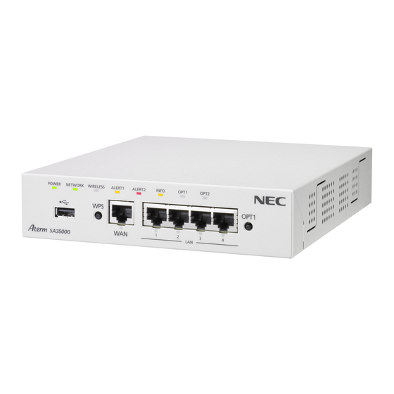
2.3. Product Specification 2.3.1. Product Exterior [Perspective view] [Bottom view (When the stand is installed)] About the Product|... - Page 25 [Front view] ALERT2 lamp INFO lamp ALERT1 lamp OPT1 lamp WIRELESS lamp OPT2 lamp NETWORK lamp OPT1 switch USB port WPS switch LAN port/LAN port status indicator WAN port/WAN port status indicator lamp Antenna connector *Not support Anti-theft hook [Back view] AC adapter connector OPT2 switch RESET switch...
-
Page 26: Basic Specifications
2.3.2. Basic Specifications [Hardware Main Specifications] Item Specification Remarks Physical 8 PIN modular jacks (RJ-45) UTP cable (at least CAT5e) interface interface Number of 1 port ports Type 1000BASE-T/100BASE-TX (IEEE802.3ab/IEEE802.3u) Auto MDI/MDI-X Physical 8 PIN modular jacks (RJ-45) UTP cable (at least interface interface CAT5e) - Page 27 Corresponding laws and Lead Free regulations and quality RoHS support standards Antenna connectors are not supported. ・ [Firmware Main Specifications] Item Specification Remarks NAPT session Up to 30,000 sessions Refer to Section 3.6.7 for the management function description. Number of PPPoE sessions 1 session Refer to Section 3.6.8 for the function description.
-
Page 28: Lamp Indicator
2.3.3. Lamp Indicator Display Name Lamp Indication Function Remarks Illuminating in green Power is on. Normal state Do not turn off this product. Switches to another status indicator after Blinking in orange While writing into memory blinking orange for a certain period of time. - Page 29 Security/scan function license Illuminating in red has expired. 60 days until the license expiration of the Blinking in red security/scan function will be cut. Security/scan function can be used. Illuminating in State where firmware can be orange upgraded. Restarts after normal termination. Blinking in orange Ongoing firmware upgrade.
- Page 30 WAN port link is established. Illuminating in green WAN port is transmitting and Blinking in green receiving data. WAN port link is not established. Illuminating in green LAN port link is established. LAN port is transmitting and Blinking in green receiving data.
-
Page 31: Device Label
2.3.4. Device Label ■Sample Product Type : ZA-SA3500G/1B |About the Product... -
Page 32: Components
2.4. Components Check that all components are complete. ■ Components □ SA3500G □ Stand □ Ethernet cable (Straight,about 2m) □ AC adapter □ AC power cord □ Terms and Conditions □ Rubber footing (4 pieces) □ Stand screw(1 piece) Always use the included AC adapter and power cord on this product. Moreover, do not use the AC adapter on other products. -
Page 33: Function Specification
3. Function Specification The functional overview of this product is as follows. Function Description Security/scan Function Firewall (FW), Antivirus (AV), Intrusion Prevention System (IPS), Web Guard (WG), URL Filter (UF), URL Keyword Filter (KF), Application Guard (APG) Logs and statistical information related to Security/Scan Function ... - Page 34 The differences in the corresponding functions by the firmware version are as follows: Firmware Version 5.0.10 Corresponding Operational Mode Bridge Router Security/Scan Function Firewall (FW) ○ ○ Antivirus (AV) ○ ○ Antivirus extended ○ ○ scan Intrusion Prevention ○ ○ System (IPS) Web Guard(WG)...
- Page 35 Setup Values Restart ○ ○ Time Setting ○ ○ IPv4 Packet Filtering ○ ○ MAC Address Filtering ○ ○ ping ○ ○ traceroute ○ ○ Self-diagnosis ○ ○ Maintenance Function ○ ○ Packet dump ○ ○ Bridge Function DNS Resolver Function ○...
-
Page 36: Protocol Stack
3.1. Protocol Stack The image of the protocol stack of this product is as follows. This product classifies packets to be detected by the security/scan function and packets not to be detected on the input interface. 3.1.1. Bridge Mode [Detected packets of security/scan function] IPv4/IPv6 Scan Function IPv4/IPv6... -
Page 37: Router Mode
3.1.2. Router Mode [When WAN IP is fixed or set at DHCP] Scan function IPv4 IPv4 IPv4 IEEE802.1 Bridge IEEE802.1 Bridge IEEE802.3(MAC) IEEE802.3(MAC) IEEE802.3(MAC) IEEE802.11(MAC) IEEE802.3(MAC) IEEE802.11(MAC) Air-PHY Air-PHY Node SA3500G Node [When PPPoE is used] Scan function IPv4 IPv4 IPv4 IEEE802.1 Bridge IEEE802.1 Bridge... -
Page 38: Installable Network
3.2. Installable Network The following network environment is necessary when using this product. This product must be able to communicate over the Internet. ・IPv4 address is required for this product. ・This product requires the following communication. Allow sending/receiving of traffic of this product to its host. -
Page 39: Bridge Mode
3.2.1. Bridge Mode Availability column:○…No limitation ○*…With some limitations (* Refer to the Supplementary Explanation column) ×…Not supported Network Availability Supplementary Explanation A router (A broadband router or home ○ gateway is included) is set up. An IPv6 network only. ×... -
Page 40: Router Mode
3.2.2. Router Mode Availability column:○…No limitation ○*…With some limitations (* Refer to the Supplementary Explanation column) ×…Not supported Network Availability Supplementary Explanation IPv4 network ○ Mixed IPv4/IPv6 network ○* This product does not support IPv6 packets. An IPv6 network only ×... -
Page 41: Security/Scan Function
3.3. Security/Scan Function 3.3.1. Security/Scan Function Overview This product offers the following security/scan functions. Security/Scan Function Abbreviation Detection Type Description Firewall Access control DoS attack detection, SPI Antivirus *1 Threat detection Detection and removal of virus (data rewriting). Intrusion Prevention System Threat detection Prevention of network attacks. -
Page 42: Disclaimer
3.3.3. Disclaimer This product decreases security risks. NEC does not guarantee the elimination of all of the security risks. Due to the characteristics of this product, the following events might occur. This product regularly updates the signature (information on the virus definition, etc.). The signature, in order to ... - Page 43 [Operation after activation is executed] When it is started for the first time, the activation operation is necessary for using the security/scan function of this product. Activation means “The use of this product starts in the agreement with the terms of use of this product“. Product Server ☞...
- Page 44 [Operation at normal startup] When this product starts, the license is confirmed. When the response of the completion confirmation is received from the server, the security/scan function of this product is enabled. The bridging/routing function of this product does not operate until the security/scan function is enabled.
-
Page 45: License Expiration Operation
3.3.5. License Expiration Operation The operation when the security license of this product expires is as follows. [Operation when license expires] When the license expires, the bridge/router function of this product is invalidated. *In case packet forwarding is performed when security function is disabled, change the settings referred in Section 5.8.2. - Page 46 [Additional License (1 year) license extension] For one-year, five-year, six-year licensed products, "SA3500g Additional License (1 year)" (Part number: ZA-SA/LA1) is available separately to extend the license for one year (365 days), including basic maintenance. The license extension period for this product is up to seven years, including the initial license period from the start date of use. To extend the license for this product, make a purchase before the license expires.
-
Page 47: Firewall
3.3.6. Firewall (FW) Detects unauthorized access, such as DoS attacks, and discards the unauthorized access packets. This product intercepts unauthorized access from the outside by Stateful Packet Inspection (SPI) function. The Stateful Packet Inspection is a function that dynamically reads data packets that passes the firewall, judges the content, and opens/closes the port. -
Page 48: Antivirus
3.3.7. Antivirus (AV) A function that rewrites the program and render it harmless when a virus or dangerous code is detected. User Network SA3500G Cleans the virus It monitors web browsing, received emails and communication of other applications and checks whether a virus exists in the downloaded or uploaded file. - Page 49 [File type to be detected] File detected by signature: ・exe, dll, com, elf, scr, js Files to be detected by the database server we manage when extended scanning is enabled: ・doc (doc(x), ppt(x), xls(x), msi), pdf, bat, cmd, com, vbs, wsf, js *When extended scanning is enabled, com and js is detected by both signature and database server.
- Page 50 [How to stop the security function] When a normal file is erroneously detected as a threat, stop the function temporarily using the following method. Stopping the operation of the security function increases security risk. Therefore, stop the function after confirming your risks and responsibility.
-
Page 51: Intrusion Prevention System
3.3.8. Intrusion Prevention System (IPS) This detects anomalies such as attack codes in traffic and blocks traffic where anomalies are detected. Prevention Internet User Network SA3500G It can prevent attacks by detecting pattern and matching pre-registered intrusion methods and prevents communication when an attack to the network that cannot be detected by a firewall is recognized. - Page 52 [How to stop the security function] When a normal access is erroneously detected as a threat, stop the function temporarily using the following method. Stopping the operation of the security function increases security risk. Therefore, stop the function after confirming your risks and responsibility.
-
Page 53: Contents
3.3.9. Web Guard (WG) This guards against dangerous web sites such as phishing sites and browsing that may cause virus infections. Prevention Internet User Network SA3500G [Detection contents] It detects traffic to dangerous websites, and blocks access to the concerned website. Type of Traffic Description HTTP traffic... - Page 54 [Behavior of operation and notification when threat is detected] Block setting Operation during detection How to notify during detection How to cancel detection state Access to concerned website is ・ALERT1 lamp *1 ・Orange ALERT1 lamp light is blocked. blinking orange (60 seconds) cancelled by any of the following ->Orange lights up methods.
- Page 55 [Check URL range] For HTTP traffic, it refers to both the host and path parts of the URL. For HTTPS traffic, it refers only to the host part of URL. (Do not refer to the path part.) From this difference, the detection result is the same when the host part is the same even if the path part is different for HTTPS traffic, while the result may be different for different paths even if the host part is the same traffic for HTTP.
-
Page 56: Url Filter
3.3.10. URL Filter (UF) Viewing is limited by specifying the website category prepared beforehand. As a result, access to harmful sites and non-business related sites are blocked. Known site(URL) Block according to the category Internet User Network SA3500G During web browsing, access to known site (URL) is intercepted based on the website category. It is set beforehand which category is to be blocked. - Page 57 HTTPS Port number to be detected : 443 HTTP detection method : GET, POST *May not be able to detect HTTP1.0. [Setting individual permission] Specific website access not included in the threat detection can be set. [Behavior of operation and notification when threat is detected] ...
- Page 58 Log only setting Operation during detection How to notify during detection How to cancel detection state Log output only Log in the security log - (It is necessary to view it in Web setting.) [How to stop the security function] When a normal website is erroneously detected as a threat, stop the function temporarily using the following method.
- Page 59 Individual Category Individual Category Supplementary Description Pornography Selected automatically when the “Adult site category“ is blocked. Nudity and Potentially Adult Content Selected automatically when the “Adult site category“ is blocked. Gambling and Lottery Selected automatically when the “Adult site category“ is blocked. Alcohol and Tobacco Selected automatically when the “Adult site category“...
- Page 60 Malware Selected automatically when the “Dangerous site category“ is blocked. Black Hat SEO Sites Selected automatically when the “Dangerous site category“ is blocked. Malicious APP Selected automatically when the “Dangerous site category“ is blocked. Advertisements and Pop-Ups Portals and Search Engines Transportation Real Estate Finance and Insurance...
-
Page 61: Url Keyword Filter(Kf
3.3.11. URL Keyword Filter(KF) By registering a specific string beforehand, access to the website of the URL that contains the corresponding string is blocked. If there is a URL for which access needs to be prohibited, use this function to set the URL to prohibit access. Set the character string in the Web setting. - Page 62 <When keyword is matched> This product sends a message to the terminal to indicate that an access to the website containing any keyword is detected. *Since SSL handshake has failed, the traffic to the corresponding website is blocked for HTTPS. [Allowed keywords] Characters that can be used: ASCII code from 0x21-0x7e, multibyte characters (excluding“...
- Page 63 [How to stop unintended detection] How to stop Remarks Stop by using either of the following methods. ● Delete the keyword set at “Keyword List“ with the “Delete“ button from “URL Keyword Filter setup“. (Refer to Section 5.8.8) ● Remove the check on “Enable Keyword Filter“ from “URL Keyword Filter setup“...
-
Page 64: Application Guard(Apg
3.3.12. Application Guard(APG) This restricts the use of application that many unspecified number of individuals can exchange information such as file sharing, software and video sharing application, messenger application, etc. This prevents the spread of virus and information leakage from the other party and malicious party who are do not have security measures. Restricted use of application and traffic is set at Web setting. -
Page 65: Security Log
3.3.13. Security Log The detection status of this product's security/scan function can be confirmed in the log messages. These log messages can be saved in computers. [Content of log message] Detection date Name of function (FW, AV, IPS, WG, UF, KF, APG) ... -
Page 66: Mail Notification
3.3.14. Mail Notification This function informs through email when threat detection has occurred. Moreover, monthly statistics can be sent as monthly report to the administrator. Refer to Section 5.8.11 for the setting method. (1) [Email notification setting] Administrator: admin@example.com User 1: user-b@example.com / PC-B (2)Threat detection Internet... - Page 67 [Notification recipients] There are two types of notification recipients. Notification Setting Contents Description Number of Allowed Recipient User Registrations Administrator Administrator’s email Notifies the registered email addresses when all address events set to “Notify“ have occurred. User Combination of terminal Notifies the registered email in the concerned information (MAC terminal when threat is detected in the packet...
- Page 68 ・Firmware update is available ・License expiration date ・URL filtering and application guard access information [Operation when sending of email fails] When sending fails, it resends up to three times (after 10 minutes, 30 minutes, 70 minutes) and then the process ...
- Page 69 Time:yyyy/mm/dd hh:mm:ss Comment on device Device: IP address/MAC/Comment management screen X-Forwarded-For: IP address setting item Threat SA3500G Blocking Report Blocked the following threat. ・Comment: detection (IPS) Type: IPS Comment on attacker IP: IP address device Details: msg management Time:yyyy/mm/dd hh:mm:ss screen setting item Device: IP address/MAC/Comment X-Forwarded-For: IP address...
- Page 70 [Email notification content parameter] Parameter Contents Notification Condition X-Forwarded-For The value of the X-Forwarded- If the protocol contains X-Forwarded-For or X-Tinyproxy For header or X-Tinyproxy headers in HTTP and HTTP headers. If the X-Forwarded- header contained in the HTTP For header and the X-Tinyproxy header are included at header the same time, the value of the header that is listed earlier is listed.
- Page 71 Monthly Report Subject SA3500G Monthly Report Text 2018/10 Report [Device Information] xxxx-xxxx-xxxx-xxxx [Statistics] AV:0/100 IPS:0/100 WG:0/100 UF:50/100 KF:20/100 APG:10/100 Access information <The UF category (Top 5 categories) > No Category Access count Historical average Number of blocks -- -------------------------------- ---------- ---------- ---------- News, Media...
-
Page 72: Patlite
3.3.15. PATLITE This function has the ability to turn on a PATLITE device when threat is detected. PATLITE device that can communicate with this product blinks for 5 minutes* when threat is detected. PATLITE is optional. * Red lights up. Red lights up in case of a five color display PATLITE. -
Page 73: Statistics
3.3.16. Statistics The detection status of this product's security/scan function can be confirmed through statistical information. [Statistical information contents] The number of packets intercepted and scanned items of each FW/AV/IPS/WG/UF/KF/APG function. When logging only the operation setting at the threat detection of each function of AV/IPS/WG/UF/KF/APG, the ... -
Page 74: Threat Detection
Until then, statistical information is saved in memory depending on the timing of device restart by Web setting operation. *In case of a power outage and power cutoff, statistical information that was not saved in memory is lost. [Web setting operation] Statistical information can be viewed daily, weekly, and monthly at Web setting. -
Page 75: Device Manager
3.3.18. Device Manager [Functions] Automatically detects LAN terminal information and displays it on the device management screen. (Maximum 100 units) Information to be displayed are MAC address, IP address, related information such as OS, wired/wireless classification of the detected terminal. Wired is a terminal connected to the LAN port of this product, and wireless refers to the terminal belonging to this product by wireless LAN. -
Page 76: Device Map
3.3.19. Device Map Through this product’s Web setting, the terminals connected to a wired LAN port and a wireless LAN can be visually confirmed. The devices connected to the LAN connected to this product can be checked. Use this in order to visually check the network configuration centered on this product. -
Page 77: Simple Radius Function
3.3.20. Simple RADIUS Function By enabling this function, the LAN terminal connected to the company network can be authenticated. Only the authorized LAN terminal to the internal network can be connected by registering the account information of the LAN terminal in the authentication database of this product. Unauthorized connection to the internal network can be firmly prevented by using it in together with the MAC address filtering function. -
Page 78: Maintenance Function
3.4. Maintenance Function This section explains the network function used by this product and the necessary information update for this product's security/scan function and firmware update, etc. 3.4.1. Firmware update operation There are three ways to update the firmware of this product. 1. - Page 79 [Note] The following diagram describes the firmware update procedure, as well as checking the availability of the latest firmware. Product Server Power supply ON Check when device starts After a random period, it checks if there is a new IP setup firmware from the acquired IP address.
-
Page 80: Initialization Of Setting Values
3.4.2. Initialization of Setting Values [Items to initialize] Initializing this product will return the following into their default factory settings. Information set at Web setting (Login password at Web setting is included). Updated signature during operation (list of dangerous websites, etc.). ... -
Page 81: Saving Information On A Computer
3.4.3. Saving Information on a Computer Information of this product can be saved in a computer through Web setting or in a USB device. [Information that can be saved] Setting values set at Web setting (Saved at the “Save and restore setting values” screen of the Web setting. Refer to Section 5.6.12) Log message and statistical information of security/scan function ... -
Page 82: Restart
3.4.4. Restart This product restarts when one of the following occurs. When directly restarted at Web setting. When directly initialized at Web setting and RESET switch. When setting is restored at Web setting. When the operating mode is changed at Web setting. ... - Page 83 [NTP periodic update] The transmission timing of NTP packet is as follows. Product NTP Server Device startup System start complete IP address Random period of 60 seconds Every 24 hours When communication with the NTP server fails due to no response from NTP server because of a network failure, etc., it is retransmitted in the following manner.
-
Page 84: Http Proxy Server
3.4.6. HTTP Proxy Server When the customer's network connects to the Internet through HTTP proxy server, set also the HTTP proxy server used in this product. For the update of the security/scan function and firmware update of this product, this product itself uses the Internet to communicate. -
Page 85: Event Log
3.4.11. Event Log The event log is a function to display the setting change log and the communication log of this product. Necessary information for troubleshooting can be gathered during maintenance. Event log can be saved on a computer. For the details, refer to Section 6.1.10. -
Page 86: Logout Function
3.4.12. Logout Function By performing logout, administrators can prevent operations by third parties while they are away. The automatic logout time can be changed. For the setting method, refer to Section 5.6.10. [Logout timing] When the "Logout" button is clicked at the top right of the [TOP] screen. ... -
Page 87: Snmp
3.4.13. SNMP This product is equipped with SNMP (Simple Network Management Protocol) as a network management protocol, and an SNMP manager that can retrieve this product's MIB information. It also sends the trap information to the SNMP manager when an event occurs. [Note] Settings of this product cannot be changed from the SNMP manager. - Page 88 [SNMP specifications] Item Contents Remarks SNMP version SNMPv1/SNMPv2c Access restriction Can be set Maximum of three SNMP managers can be set Trap destination Can be set Maximum of three SNMP managers can be set setting Monitoring 0:cold-start Up to 60 minutes of delay can be set in the menu “Delay possible trap time setting during SNMP trap transmission.”...
-
Page 89: Home Ip Location Function
3.4.14. Home IP Location Function Home IP location function is a function that enables accessing this product from the Internet using a home IP location name. This function is enabled in the following cases: • Set in router mode (Initial value: “Bridge mode”). •... -
Page 90: Bridge Mode Function
3.5. Bridge Mode Function The bridge function of this product operates as a transparent bridge. However, the packets to be detected by the security/scan function does not apply to this. [Note] This product differentiates the uplink and downlink interfaces unlike usual bridge devices. Connect the WAN port of this product to the Internet and the LAN port to the local area. -
Page 91: Ip Address
3.5.2. IP Address This product's IP address is as follows. Interface IP Address Remarks WAN/LAN Set by using either of the following An IPv4 address that can access the Internet is methods. needed for the update and control of the Fixed setting (Through Web setting) security/scan function of this product. -
Page 92: Ipv4 Packet Filtering
3.5.4. IPv4 Packet Filtering [Filtering point] Filtering points of this product's IP packet filtering function are as follows. ・When IPv4 packet is received at WAN interface. ・When IPv4 packet is sent at WAN interface. ・When IPv4 packet is received at LAN/wireless LAN interface. ・When IPv4 packet is sent at LAN/wireless LAN interface. -
Page 93: Mac Address Filtering
3.5.5. MAC Address Filtering This function enables communication only with the LAN terminal to which the MAC address is registered. With this, communications from the LAN terminal that has no registered MAC address can be blocked. LAN terminal refers to a terminal connected to a wired LAN interface and a wireless LAN interface. Up to 60 MAC addresses can be registered in this product each for wired LAN and wireless LAN. -
Page 94: Dns Resolver
3.5.7. DNS Resolver [Operating interface] WAN interface LAN interface [Basic specifications] Works with IPv4. IP address of the DNS server is managed up to 2 addresses. IP address of the DNS server is set using the following methods. ・At Web setting ・The IPV4 address acquired by DHCP is set. -
Page 95: Router Mode Function
3.6. Router Mode Function This product is an IPv4 router. [Note] As compared to a common router device, this product can distinguish its uplink and downlink interfaces. Connect the WAN port of this product to the Internet and the LAN port to the local area. 3.6.1. -
Page 96: Ipv4 Static Routing Function
3.6.3. IPv4 Static Routing Function [Operating interface] WAN interface and LAN/wireless LAN interface [Basic specifications] This product routes between WAN interface and LAN/wireless LAN interface. PPPoE interface specification and IPsec1 interface specification can be done as gateway specification method. *IPsec1 can be set when IPsec operation mode is route based. This product supports IPv4 static routing. -
Page 97: Napt
3.6.8. NAPT [Operating interface] WAN interface and LAN/wireless LAN interface [Basic specification] NAPT method of this product is Port-Restricted cone NAT. [NAPT session management] Up to 30,000 NAPT sessions are managed. When the number of managed NAPT sessions exceeds the maximum value, the old NAPT session is deleted ... -
Page 98: Pppoe
3.6.9. PPPoE [Operating interface] WAN interface [Basic specifications] One PPPoE session can be established. PPPoE function is based on RFC2516. PPP function is based on RFC1661. IPCP function is based on RFC1332. Authentication protocol supports PAP/CHAP. It is based on RFC1334. ... -
Page 99: Dhcp Client
3.6.10. DHCP Client [Operating interface] WAN interface [Basic specifications] It is based on RFC2131 and RFC2132. Moreover, it supports the DHCP relay function. Supported messages are as follows. Packet Direction DHCP Message Send DISCOVER, REQUEST, RELEASE, DECLINE Receive OFFER, ACK When the ACK message from DHCP server is received, ARP checks duplication of the distribution IP address. - Page 100 Transmission timing of REQUEST message is as follows. REQUEST Transmission Description Timing When OFFER is received Resends when there is no ACK received 3 seconds after transmitting. Resending is repeated twice, and if there is still no response after 20 seconds, processing is redone from DISCOVER.
-
Page 101: Dhcp Server
3.6.11. DHCP Server [Operating interface] LAN/wireless LAN interface [Basic specifications] It is based on RFC2131 and RFC2132. It does not support DHCP relay function. Supported messages are as follows. Packet Direction DHCP Message Send OFFER, ACK Receive DISCOVER, REQUEST, RELEASE, DECLINE Contents of the transmitted OFFER and ACK messages are as follows. -
Page 102: Proxy Dnsv4
3.6.12. Proxy DNSv4 [Basic specifications] Works with IPv4. Works only at router mode. The DNS client operates at the uplink interface (WAN) and the DNS server operates at the downlink interface (LAN/wireless LAN). When the DNS query packet is received from the terminal connected to the LAN/wireless LAN interface, it is sent to the DNS server. -
Page 103: Cloud Service Connection
3.6.13. Cloud Service Connection This product can connect to Amazon Web Service (AWS) and Microsoft Azure cloud service. Using cloud service connection, cloud services such as data sharing between head office and branch offices/branches can be used. The figure below shows the image of setting this product at the headquarters and branch office and connecting the cloud service. -
Page 104: Ipsec
3.6.14. IPsec This product supports IPsec communication. IPsec stands for IP security protocol, and it is used for Internet-VPN with a protocol for encrypting IP packets for secure communication. Main features are the encryption and authentication functions. Encryption guarantees confidentiality by means of data encryption. Authentication can detect peer’s authentication and alteration of packets. - Page 105 ■IKEv2 [IKEv2 overview] IKEv2 features will be outlined for those using IKEv1. IKEv2 is not compatible with IKEv1 and the terms used are different. ISAKMP-SA, IPsec-SA equivalent functions are KE-SA and Child-SA respectively. Hash algorithm is equivalent to authentication algorithm and a pseudo-random number algorithm. ...
- Page 106 Rekey Connection Type Rekey Method On-demand Perform rekey when encrypted communication using the generated SA Enable connection exists. On-demand Perform rekey regardless of the presence of the encrypted communication No Rekey connection using the generated SA. Continuous Perform rekey when there is encrypted communication using the Always connection generated SA.
- Page 107 [IKE extension] IKE SA deletion Prior to deleting the IKE SA, a DELETE message (DELETE PAYLOAD) is sent to the other end, and the IKE SA paired with the other end can be deleted. INITIAL-CONTACT During the start of IKE Phase1, it is used to notify that it is the first IPsec connection with the other system. The receiver of INITIAL-CONTACT may consider that the IPsec connection with the sender is lost, and delete its IPsec SA with the sender.
- Page 108 Source address specification Fixed setting Peer Manual deletion IKE SA deletion IKE SA deletion when “delete payload” is received “delete payload” transmission when IKE SA is deleted Continuous connection Continuous connection without traffic Rekey extension of IPsec SA/IKE SA Rekey with traffic IKEv1 On-demand connection There is traffic, but...
- Page 109 Source address specification Fixed setting Peer Manual deletion IKE SA deletion IKE SA deletion when “delete payload” is received “delete payload: transmission when IKE SA is deleted Continuous connection Continuous connection without traffic Rekey extension of IPsec SA/IKE SA Rekey with traffic On-demand connection There is traffic, but rekey is not done...
- Page 110 TCP MSS rewriting Fixed, AUTO Anti-replay defense Possible IPsec applying ACL setting (IP filter) Static, Dynamic Simultaneous operation of external connection is NAT/NAPT concurrent operation allowed by NAT/NAPT and IPsec. Others VPN pass-through One session (static NAPT method) [Note] The static routing and IPsec remote ID setting priority are as follows. When remote ID of IKE Phase2 is registered, a static route is automatically registered.
-
Page 111: Wireless Lan Function
3.7. Wireless LAN Function This product operates as an access point. This product supports IEEE802.11b/g/n (2.4GHz band). The antenna includes a built-in antenna. 3.7.1. Wireless LAN Wireless main function list is shown below. Function Details Remarks Multi SSID SSID x2 ESS-ID stealth Enable/Disable switch Wireless channel... - Page 112 ■ For IEEE802.11g 9ch (2.452GHz) 1ch (2.412GHz) 5ch (2.432GHz) 13ch (2.472GHz) ↓ ↓ ↓ ↓ Frequency 20MHz There are two ways to specify the channel be used by this product. Method Range of CH Selection At the start of the operation of this product's wireless LAN The channel between 1ch~11ch with good function, the surrounding access point is detected, and the signal condition is automatically selected.
- Page 113 [Network Isolation] The network isolation function restricts access to terminals connected to each network (SSID1/SSID2) of multiple SSIDs and terminals connected with wires and separates them from other networks connected to this product. The WAN side will not be isolated. Network isolation can be used in the router mode.
-
Page 114: Wps
3.7.2. WPS WPS-PBC (Wi-Fi Protected Setup-Push Button Configuration) is supported. Use the WPS switch on the front of this product to automatically configure the wireless LAN terminal compatible with WPS-PBC and Wi-Fi. The WPS function can be enabled/disabled through Web setting. The WPS function cannot be used under the following conditions. -
Page 115: Usb Device Function
3.8. USB Device Function The contents of this section are common specifications in bridge mode and router mode. By connecting a USB device to the USB port, settings values can be stored on the device periodically, save the settings on the Web setting, and restore the settings. Please refer to sections 3.8.1 and 3.8.2 for the procedure. -
Page 116: Save Setting Values
3.8.1. Save Setting Values If the USB storage that meets the above conditions is connected to the USB port, the setting values are saved at the following instances. A file will be saved together with a backup. When the save button is clicked ... -
Page 117: Restore Setting Values
3.8.2. Restore Setting Values This product will restore the setting value from the USB storage connected to a USB port and restarts when the following conditions are satisfied: [Restore condition] Device startup after initialization Files are saved under the USB storage (SA3500G_config.bin or SA3500G_config.bin.bak). ... -
Page 118: Other Functions
3.9. Other Functions The contents in this section are specifications common to bridge and router modes. 3.9.1. Traffic Forwarding Restrictions When all of the following requirements are met, this product operates in bridge or router mode. (Reference: Section 3.3.4) When activation has succeeded ... -
Page 119: Installation
4. Installation 4.1. Installation This section describes the installation requirements of the product. 4.1.1. Environmental Condition Operating conditions are as follows. Temperature: 0~40℃ Humidity: 10~90% (without condensation) 4.1.2. Installation Place Read the following warnings and precautions before setting. Section 1.12 Safety Instructions ... -
Page 120: Installation Procedure
4.1.3. Installation Procedure [Unpacking procedure] 1. Unpack. 2. Check that the components are complete. ・Refer to Section 2.4 for the components. 3. Check that the components are not damaged. 4. Check that the content of the device label in the product's main body matches the content in the packaging box's label. -
Page 121: Using The Anti-Theft Hook
4.2. Using the Anti-theft Hook An anti-theft hook is a key installation hole for theft prevention. This product is protected from theft by installing commercially available security wire. *The security wire may not fit the hook depending on the shape of its key. Note the shape of the key in selecting the security wire. -
Page 122: Connection Of Cables
4.3. Connection of Cables Connect the cables according to the image below. Depending on the customer environment, the installation location of SA3500G may differ. Connection examples are on Section 8.1. When connecting devices such as router/broadband modem to SA3500G WAN port, it is important for the device to allow the required TCP/UDP packets from SA3500G to pass through. -
Page 123: Setting/Setting Confirmation
5. Setting/Setting Confirmation This product is set at Web setting. [Setting screen of this product] The setting screen of this product is roughly divided into three parts. Network setting ・Bridge mode ・Router mode Security/scan function setting Settings related to configuration management function ... -
Page 124: Account
5.1. Account The login account for Web setting is as follows. Type Description Password User account Web screen that the customer usually accesses admin No initial value (User will set) Setting/Setting Confirmation|... -
Page 125: Setting Flow At Initial Startup
5.2. Setting Flow at Initial Startup The following operations are necessary during initial startup of the device. Mode selection (Wizard operation) ・Bridge mode (Refer to Section 5.2.1) ・Router mode (Refer to Section 5.2.2) Activation operation (Refer to Section 5.2.3) ... - Page 126 6. STEP2: Set the administrator password One-byte characters 0-9, a-z, and A-Z, - (hyphen) and _ (underscore) can be used for the password. Password can have 1-64 characters. *The administrator password is the login password at the Web setting of this product. *The set password is saved in memory by clicking the “Apply”...
- Page 127 ■When IPoE is selected (automatic acquisition) ■When IPoE (manual setting) is selected |Setting/Setting Confirmation...
- Page 128 8. STEP4:Other settings. Set the appropriate content in accordance with your security policy. Check if packet forwarding is allowed even when the security/scan function is disabled. The initial value is unchecked. The security/scanning function may be disabled, such as when the security license for this product expires. In that case, put a check for packet forwarding.
- Page 129 9. The Web setting login screen of this product will open, enter user name and password. User name:admin Password: Password set according to procedure 6 (STEP2) |Setting/Setting Confirmation...
- Page 130 10. When the above procedures are completed, it will move to the TOP screen. Activation If this is displayed in the screen, the following can be considered. ・Activation is incomplete (first time only) ・License check is incomplete after device startup. ...
-
Page 131: Router Mode Operation
5.2.2. Router Mode Operation Set according to the following procedures. 1. Connect the cables to this product. (Refer to Section 4.5) 2. Set the IP address of the computer to set this product to 169.254.xxx.xxx/16. (xxx is an arbitrary integer from 1 - 254. Set the IP address except 169.254.254.11.) 3. - Page 132 6. STEP2: Administrator password is set. One-byte characters 0-9, a-z, and A-Z, - (hyphen) and _ (underscore) can be used for the password. Password can have 1-64 characters. *The administrator password is the login password at the Web setting of this product. *The set password is saved in memory by clicking the “Apply”...
- Page 133 ■When selecting IPoE (automatic acquisition) ■When IPoE (manual setting) is selected |Setting/Setting Confirmation...
- Page 134 ■When selecting PPPoE 8. STEP4:Other settings. Set the appropriate content in accordance with your security policy. Check if packet forwarding is allowed even when the security/scan function is disabled. The initial value is unchecked. The security/scanning feature may be disabled, such as when the security license for this product expires. In that case, put a check for packet forwarding.
- Page 135 10. After completing the above procedure, user will be redirected to TOP screen. If this is displayed in the screen, the following can be considered. ・Activation is incomplete (first time only) ・License check is incomplete after device startup. 11. Set the network of this product. (Refer to Section 5.7) Activation 12.
-
Page 136: Activation
5.2.3. Activation Activation operation is necessary in order to use the security/scan function of this product. [Implementation timing] Only at initial startup Set this product and operate according to the following when internet communication is available (NETWORK lamp turns green or orange). [Advance preparation] Make sure that this product is able to communicate with the Internet. - Page 137 [Note] The license use start date is the date of successful activation or 31 days after delivery of this product, whichever is earlier. Activation cannot be canceled after activation is successful. |Setting/Setting Confirmation...
-
Page 138: Setup Screen Configuration
5.3. Setup Screen Configuration The setting procedure of this product is as follows. Login screen TOP page Network topology Maintenance function Security function setting setting setting *The contents displayed on the screen vary depending on the operation mode. Refer to the following sections for the “Maintenance” screen structure. Bridge mode Section 5.6.1 Router mode... -
Page 139: Login
5.4. Login This section describes the login procedure when accessing this product. 1. Connect a computer to the LAN port of this product. 2. For bridge mode, set the computer's IP address to 169.254.xxx.xxx/16 (*1), then access http://169.254.254.11/ on a web browser. (*1) xxx is an arbitrary integer from 1-254. - Page 140 4. TOP page opens. [Note] When the computer's IP address is changed, return it to its original setting after the completion of the setting of this product. By default, the login screen cannot be accessed from the WAN port. If access is required, permission can be set ...
-
Page 141: Save Settings
5.5. Save Settings There is a “Save” button in both Security and Maintenance screens. Either of the “Save” button in either screen saves all the settings in the memory. When the USB storage is connected to the USB port, the setting contents are also saved in the USB storage. Save Button Description Status... - Page 142 [Maintenance screen] If the “Save” button is blinking orange, it indicates that there is a setting item not saved in memory. *The setting values set in the Security screen are also saved in memory. Save Button *The figure above is an example of the screen in bridge mode. Location of the Save button is the same in router mode.
-
Page 143: Maintenance Setting (Bridge Mode)
5.6. Maintenance Setting (Bridge Mode) View settings and information other than the security/scan function of this product. 1. Click [Maintenance] from the TOP page. Click 2. [Maintenance] setup screen opens. Setting/information window Save Button Navigation Panel |Setting/Setting Confirmation... -
Page 144: Maintenance Screen Structure
5.6.1. Maintenance Screen Structure The maintenance setting screen structure for bridge mode is as follows. Item Description Required Operation/ Remarks Maintenance (Bridge mode) Bridge and maintenance setting Basic Setup Network setting of this product Connection Setup Switch to router mode *This product needs to be restarted when switched. - Page 145 Information Product version and operating status display Device Status Product information (device ID, serial number, MAC address, and version information) Operation mode Wireless LAN information IP address of product Device Information Wi-Fi Information ARP table MIB Information SNMP MIB information Event Log Operation log of this product Diagnostics...
-
Page 146: Product Ip Address Setting
5.6.2. Product IP Address Setting Be sure to implement if the product’s IP address is not acquired from the DHCP client function. In order to use the security/scan function of this product, a management IPv4 address that can access the internet is necessary. - Page 147 Setting Item Value Remarks Initial Value DHCP Client • Checked: IP address of this product is Enabled Function acquired in the DHCP client function. • Unchecked: Set the IP address of this product on this setting screen. IPv4 Address/ Input the IPv4 address and netmask for The IPv4 address is set as the Not set Netmask...
-
Page 148: Wireless Lan Setup
https://[domain name]:[port number]/ The number of characters that can be inputted is 256. Set the proxy server with HTTP when accessing the Web setting via HTTP. Set the proxy server with HTTPS when accessing the Web setting via HTTPS. 5.6.3. Wireless LAN Setup The network isolation cannot be used in bridge mode. -
Page 149: Ipv4 Static Routing
5.6.5. IPv4 Static Routing Up to 50 static routing entries can be added. 1. Open the [TOP]-[Maintenance]-[Network]-[IPv4 Static Routing] screen. 2. Click “Edit” to see the screen below. 3. Set the routing entry information. 4. Click the “Apply” button. 5. Click the “Save” button. Setting Item Value Remarks... -
Page 150: Packet Filter Entry Setup
5.6.6. Packet Filter Entry Setup Passing and discarding of packets that meet specific conditions can be set. This function is common to bridge and router mode. It differs only in that there is no target interface selection in bridge mode. 1. - Page 151 Setting Item Value Remarks Initial Value IPv4 Packet Filter Up to 50 entries can be set Entry Edit for each filter point. Entry No. Input the entry number Set IPv4 packet filter entry 1 in the initial state. Though editing and deleting is allowed, it is recommended to use it as it is.
-
Page 152: Mac Address Filtering Setup
5.6.7. MAC Address Filtering Setup This is a function to connect with this product for specific LAN terminals only. Up to 60 entries can be registered each for wired LAN and wireless LAN. Select the target type and press the "Select" button to switch the MAC address entry screen. ■Wired LAN MAC address filtering screen 1. - Page 153 Setting Item Value Remarks Initial Value MAC Address Filtering Select Interface • Wired LAN: Select this to set MAC Wired Type address filtering for the wired LAN interface. • Wireless LAN: Select this to set MAC address filtering to the wireless LAN interface.
- Page 154 3. Click "Edit" to enter the edit screen and add the wireless MAC address to be connected. 4. Check the SSID that enables MAC address filtering function. 5. Click the "Apply" button. 6. Click the "Save" Value Remarks Initial Value button.
- Page 155 ■MAC address filtering entry edit screen This is the entry edit screen for wireless LAN. The entry edit screen for wired LAN is also the same. 1. Enter the MAC address of the LAN terminal to be connected. Select from the MAC address list with access history by clicking the "Display Access History" button. 2.
-
Page 156: Ethernet Port Setting
5.6.8. Ethernet Port Setting The communication mode and WAN and LAN port media type and flow control can be set in this product. The initial value is automatic setting (Auto Negotiation). Use it when fixed setting is necessary in environment to be used by customers. -
Page 157: Snmp Agent Setting
MDI/MDI-X Select MDI /MDI-X mode from the following. The configurable items of Automatic - Auto MDI WAN port and LAN ports - MDI 1-4 are the same. Set - MDI-X according to customer environment. Flow control Checked: when using flow control The configurable items of Disabled Unchecked: when not using flow control... -
Page 158: Access Web Setting
5.6.10. Access Web Setting It is recommended to periodically change the password to access Web setting. Set (change) the administrator password when logging in to this product and the logout time. 1. Open the [TOP]-[Maintenance]-[Maintenance]-[Access Web Setting]. 2. Change the administrator password. 3. - Page 159 Confirm New Input the same character string set The characters that can be used are Not set Password as “new password“. one-byte characters 0-9, a-z, and A- Z, - (hyphen) and _ (underscore).The number of characters that can be inputted is 1- Logout Setting Timeout Time Enter the time from last Web...
-
Page 160: Time Setting
5.6.11. Time Setting The time of this product is acquired from the NTP server. Refer to this section when an NTP server is specified. One NTP server information can be set. When this product restarts, time information is not saved (time information is reset). ... - Page 161 Setting Items Value Remarks Initial Value Automatic Time Setting Automatic Time • Disable: when not using NTP When an NTP server is not used, Specify NTP Server Setup Function server the time of this product is set to Name • Specify NTP Server Name: when the time entered in the current using NTP server time field.
-
Page 162: Save And Restore Settings
5.6.12. Save and Restore Settings Setting values set on the Web setting can be saved to a computer. Saved setting values can be restored to this product. [Save Setup Value] 1. Open [TOP]-[Maintenance]-[Maintenance]-[Config File]. 2. Click “Save to File” to save the setting values. [Restore Setup Value] 1. -
Page 163: Factory Default
5.6.13. Factory Default Setting values can be returned to its initial state through the Web setting. 1. Open [TOP]-[Maintenance]-[Maintenance]-[Factory Default]. 2. Click the “Initialization” button. 3. Click the “OK” button in the popup message window. 4. This product restarts automatically. [Note] Activation contents do not return to its initial state. -
Page 164: Firmware Update
5.6.14. Firmware Update The firmware of this product can be updated in the following methods. Set the firmware update method according to customer operation policy on this product. Update Method Description The firmware is updated by This product regularly accesses the management server, and confirms the using the maintenance availability of a new firmware. - Page 165 [Firmware Update (1)] When "Information" is selected as the update method 1. The INFO lamp lights up orange when a new firmware is available. 2. Press the OPT2 switch for at least two seconds. 3. The INFO lamp blinks orange when firmware update starts. Release OPT2 switch when the light blinks orange.
- Page 166 [Firmware Update (3)] When "Time Specified Update" is selected as the update method 1. Open [TOP]-[Maintenance]-[Maintenance]. 2. In the "Update Method", set the time for automatic update in the Time Specified Update. 3. Click the “Apply” button. 4. If a new firmware is available when this product accesses the management server, the INFO lamp lights up orange. At this time, this product downloads the new firmware from the management server.
- Page 167 ■When the Web setting is used (Local file specification) [Setting] 1. Open [TOP]-[Maintenance]-[Maintenance]. 2. Click the "Browse" button (may vary depending on the browser) of "Manually Update Firmware" to select the new firmware file saved in the computer. 3. Click the “Update” button. 4.
-
Page 168: Restart
5.6.15. Restart This product can be restarted in the Web setting. A message will be displayed when there is an unsaved setting value. In necessary, click the “Save” button, and save the setting values in memory. [Note] This product will restart at the following instances. Initialization ... -
Page 169: Maintenance Mode
5.6.16. Maintenance Mode On the Web setting, the maintenance mode can be activated by the operator. This is normally disabled. To use the maintenance mode, a separate maintenance account is required. [Maintenance mode setting] 1. Open the [Maintenance Mode] screen from [TOP]-[Maintenance]-[Maintenance]. 2. -
Page 170: Switch To Router Mode
5.6.17. Switch to Router Mode This product restarts when it is switched to router mode. Settings are also initialized. 1. Open the [Connection Setup] screen from [TOP]-[Maintenance]-[Basic Setup]. 2. Select “Router” for mode setting. 3. Click the “Apply” button. 4. Click the “OK” button on the restart message window. 5. -
Page 171: Maintenance Setting (Router Mode)
5.7. Maintenance Setting (Router Mode) View settings and information other than the security/scan function of this product. 1. Click [Maintenance] from the TOP page. Click 2. [Maintenance] setup screen opens. Save Button Navigation Panel Setting/Information window |Setting/Setting Confirmation... -
Page 172: Maintenance Screen Structure
5.7.1. Maintenance Screen Structure The maintenance setting screen structure for router mode is as follows. Item Description Required Operation/ Remarks Maintenance (Router mode) Router and maintenance setting Basic Setup Network setting of this product Connection Setup Switch to bridge mode Change the WAN interface operation type *This product needs to be restarted when switched to bridge mode. - Page 173 Config File Saving and restoring settings It is recommended to save the setting values when changes are made. Factory Default Execution of initialization of setting Maintenance Firmware setting Be sure to check. Restart Product restart Maintenance Mode Maintenance function setting Setting to enable the maintenance function Information...
-
Page 174: Ipv4 Lan Interface Setting
5.7.2. IPv4 LAN Interface Setting Set this to change the IP address of the LAN interface of this product. 1. Open [IPv4 LAN] screen from [TOP]-[Maintenance]-[Basic Setup]. 2. Change the product's IP address is changed according to the customer's network. 3. -
Page 175: Ipv4 Wan Interface Setting
5.7.3. IPv4 WAN Interface Setting Set the IP address of this product's WAN interface using any of the following methods. Fixed setting Set using the DHCP client function Set using the PPP function Set according to the following procedures. 1. Select the type of WAN interface operation ->... - Page 176 Setting Item Value Remarks Initial Value Connection Select the protocol to operate on Destination the WAN interface of this Selection product. IPv4 • Select IPoE if the IP address of The DHCP client and PPP functions are IPoE the WAN interface is set to set on different setting screens.
- Page 177 ◆IP address and default gateway address setting 1. Open the [IPv4 WAN (IPoE)] screen from [TOP]-[Maintenance]-[Basic Setup]. 2. Remove the check on the DHCP client function check box. 3. Input IP address under “IPv4 Address/Netmask“. 4. Input the IP address of the default gateway on “Fixed Address” under “Gateway“. 5.
- Page 178 Setting Item Value Remarks Initial Value DHCP Client • Checked: When network Set the DNS Server address at [TOP]- Enabled Function information of WAN [Maintenance]-[Network]-[DNS] when interface is acquired via DHCP client function is not used. DHCP client function. • Unchecked: When fixed network information on WAN interface of this product is used.
-
Page 179: Ppp/Pppoe Setup
5.7.4. PPP/PPPoE Setup The PPP function of this product requires PPP authentication ID/password setting. 1. Open the [PPP Setup] screen from [TOP]-[Maintenance]-[Basic Setup]. 2. Set the PPP ID and password for authentication. 3. Click the “Apply” button. 4. Click the “Save” button. |Setting/Setting Confirmation... - Page 180 Setting Item Value Remarks Initial Value Connection Set ID/password used for PPP PPP authentication protocol supports PAP and Destination Settings authentication CHAP. Authentication protocol is selected automatically according to the instructions of the BAS (server). Username Set the user name to be used Allowed characters are alphanumeric Not set for PPP authentication...
- Page 181 Keepalive parameters Transmission Transmission Transmission interval: Retry interval = 10 sec interval = 30 interval = 30 Retry frequency = 3 30 sec Retry interval: 10 sec Retry frequency: 3 Establish Keepalive Keepalive Keepalive disconnection |Setting/Setting Confirmation...
-
Page 182: Dhcp Client Setting
5.7.5. DHCP Client Setting When the IP address of the WAN interface of this product is acquired through the DHCP client, set it on this screen. 1. Open the [IPv4 WAN (IPoE)] screen from [TOP]-[Maintenance]-[Basic Setup]. 2. Check the following items. ・... -
Page 183: Mtu Setting
5.7.6. MTU Setting The MTU value of the WAN interface can be changed on this screen. 1. Open [TOP]-[Maintenance]-[Basic Setup]-[IPv4 WAN (IPoE)] screen. 2. Set the MTU value. Change according to customer’s network. The range is 1000-1500 (initial value). 3. Click the “Apply” button. 4. -
Page 184: Dhcp Server
5.7.7. DHCP Server When the IP address of the LAN interface of this product is changed, change the assigned address of the DHCP server function. 1. Open the [IPv4 LAN] screen from [TOP]-[Maintenance]-[Basic Setup]. 2. Change it according to customer's network. 3. - Page 185 Setting Item Value Remarks Initial Value DHCP Server DHCP server address setting DHCP Server • Checked: when the Enabled Function DHCP server function is used. • Unchecked: when the DHCP server function is not used. Leased Time Set the lease time, A value of '0' is not (hours) ranging from 1~72...
-
Page 186: Wireless Lan Setting
5.7.8. Wireless LAN Setting This product operates as an access point. Refer to Section 5.10.5 for the WPS switch operation. 5.7.8.1. When using this product as a wireless LAN access point 1. Open the [Wireless Setup] screen from [TOP]-[Maintenance]-[Wireless Setup]. 2. - Page 187 5.7.8.2. When authenticating with the internal RADIUS server When using the RADIUS server in this product, set the RADIUS server on the [Simple RADIUS function] screen. For the details, refer to Section 5.8.12. 1. Open the [Wireless Setup] screen from [TOP]-[Maintenance]-[Wireless Setup]. 2.
- Page 188 5.7.8.3. When authenticating with an external RADIUS server 1. Open the [Wireless Setup] screen from [TOP]-[Maintenance]-[Wireless Setup]. 2. Check "Enable" under the "Wireless Function". 3. Change the encryption mode to "802.1x (EAP)". 4. Change "Authentication Server Type" to "External". 5. Enter the setting value of the external authentication server. 6.
- Page 189 Setting Item Value Remarks Initial Value Select Wireless LAN • Primary SSID profile • Secondary SSID Wireless LAN Access point setting Access Point Setting (parent device) Wireless • Checked: when wireless LAN Both primary and Function function is used. secondary are •...
- Page 190 • WPA/WPA2-PSK(AES) • 802.1x(EAP) WPA Encryption Set the encryption key. 8~63 digits of alphanumeric Enter different values Key (PSK) characters (0~9, a~z, A~Z, for both primary and symbol), or 64-digit secondary for each hexadecimal number (0~9, device a~f, A~F) Encryption Key Set the encryption key update Primary and Update Interval...
-
Page 191: Wps Setting
5.7.9. WPS Setting Enabling/Disabling of WPS function can be done through Web setting. 1. Open the [WPS Setup] screen from [TOP]-[Maintenance]-[Wireless Setup]. 2. Check "Enable" from "WPS (PBC)" to use the WPS function. 3. Click the “Apply” button. 4. Click the “Save” button. Setting Item Description Initial Value... -
Page 192: Port Forwarding Setting
5.7.10. Port Forwarding Setting Port forwarding entries can be set. [Port forwarding entry setting] 1. Open the [Port Forwarding] screen from [TOP]-[Maintenance]-[Network]. 2. Click “Edit” to go to the following screen. 3. Set the port forwarding entry information. 4. Click the “Apply” button. 5. - Page 193 Setting Item Value Remarks Initial Value NAT Entry Edit 50 entries can be set. Entry No. Number of entries. The one with the small entry number is Not set given priority. LAN Host Specify the IP address of the Not set port forwarding target host (e.g., computer).
-
Page 194: Dns Server Setting
5.7.11. DNS Server Setting Set a fixed DNS server address when setting a fixed WAN interface IP address or a DNS server cannot be acquired through DHCP or PPPoE. 1. Open the [DNS] screen from [TOP]-[Maintenance]-[Network]. 2. Set the DNS server address. 3. - Page 195 IPv4 Primary Set the IPv4 address of the Not set primary DNS server. IPv4 Secondary Set the IPv4 address of the Can be omitted. Not set secondary DNS server. |Setting/Setting Confirmation...
-
Page 196: Ipv4 Statistic Routing Setting
5.7.12. IPv4 Statistic Routing Setting Up to 50 static routing entries can be added. *Take note when IPsec1 is selected in the interface The setting of the "IPsec 1" interface is enabled only by setting the VPN operation mode to the route base in IPsec setting. - Page 197 Setting Item Value Remarks Initial Value IPv4 Static Routing 50 entries can be set. Entry Edit Entry No. Number of entries. Not set Destination IP Specify the destination network Not set Address of the routing entry. Specification • Interface: When specifying a Not set Method routing destination with an...
-
Page 198: Ethernet Port Setting
5.7.13. Ethernet Port Setting Same setting with maintenance (bridge mode). Refer to Section 5.6.8. 5.7.14. ICMP Redirect Message Setting This product can set whether ICMP Redirect message is sent or not when a packet is received sending an ICMP Redirect message. 1. -
Page 199: Cloud Service Setting
5.7.15. Cloud Service Setting This product can use AWS or Azure's cloud connection service. Since the AWS and Azure setting items are different, a separate setting screen for each is prepared. 5.7.15.1. Amazon Web Services 1. Open the [Cloud Service] screen from [TOP]-[Maintenance]-[VPN]. 2. - Page 200 Setting Item Value Remarks Initial Value Cloud Service Settings Cloud Service Function • Checked: When using Cloud Disabled service function • Unchecked: When not using Cloud service function Service Type • AWS (Amazon Web Services) Not Set • Microsoft Azure (Route Based) •...
- Page 201 Maximum route acceptance setting Number of routes 4096, warning-only specification IPsec IPsec IPsec function setting IKE version IKEv1 TCP/MSS adjustment Automatic IKE phase Key Exchange Main mode 1 setting Method Local ID specification Not specified Remote ID Not specified specification Encryption algorithm AES128-CBC Authentication...
- Page 202 5.7.15.2. Microsoft Azure (Route Based) 1. Open the [Cloud Service] screen from [TOP]-[Maintenance]-[VPN]. 2. By checking cloud service function, the service type can be selected. 3. From the Service type, select Microsoft Azure (Route Based). 4. Set destination and source and IKE pre-shared key. 5.
- Page 203 Setting Items Value Remarks Initial Value Cloud Service Settings Cloud Service Function • Checked: When using Cloud Disabled service function • Unchecked: When not using Cloud service function Service Type • AWS (Amazon Web Services) Not Set • Microsoft Azure (Route Based) •...
- Page 204 By setting Microsoft Azure (Route Based), the following fixed values can be set. Although IPsec settings can be changed on the IPsec setting screen, it is recommended to use the settings as set on the Cloud Service Setting screen. Note that if the setting on the IPsec setting screen is changed, cloud connection may not be available.
- Page 205 Lifetime 3600 seconds Lifetime data amount Not specified Disabled Rekey Enable Rekey remaining time Not specified 5.7.15.3. Microsoft Azure (Policy Based) 1. Open the [Cloud Service] screen from [TOP]-[Maintenance]-[VPN]. 2. By checking cloud service function, the service type can be selected. 3.
- Page 206 Setting Items Value Remarks Initial Value Cloud Service Settings Cloud Service Function • Checked: When using Cloud Disabled service function • Unchecked: When not using Cloud service function Service Type • AWS (Amazon Web Services) Not Set • Microsoft Azure (Route Based) •...
- Page 207 By setting Microsoft Azure (Policy Based), the following fixed values can be set. Although IPsec settings can be changed on the IPsec setting screen, it is recommended to use the settings as set on the Cloud Service Setting screen. Note that if the settings on the IPsec setting screen are changed, cloud connection may not be available.
-
Page 208: Ipsec Setting
5.7.16. IPsec Setting This product supports IPsec. IKEv1 and IKEv2 can be used as the key exchange method. Since setting is different, IKEv1 and IKEv2 are described separately ■IKEv1 1. Open the [IPsec] screen from [TOP]-[Maintenance]-[VPN]. 2. Select IKEv1 as the IKE version. Setting/Setting Confirmation|... - Page 209 3. Input IPsec settings. 4. Click the "Apply" button. 5. Click the "Save" button. Setting Item Value Remarks Initial Value IPsec Settings IPsec Function • Checked: when the IPsec function is Disabled used. • Unchecked: when the IPsec function is not used. IKE Version •...
- Page 210 IKE Mode • Main mode: select when the IP The fixed key method is Main mode address of both the IPsec tunnel and not supported. this product’s IPsec peer device has a fixed value • Aggressive mode: select when the IP address of either this product or its IPsec peer device, or the IPsec tunnel is undefined.
- Page 211 • Key-ID: Random character string • User-FQDN: Domain name with a user name Remote ID Set ID according to the format of the Sample input Not set selected "Remote ID Setting". IP address: 192.0.2.222 • IP address: IP address format FQDN: •...
- Page 212 communication disconnection of the When this function is IPsec tunnel. enabled, the DPD packet • Checked: when DPD-Keepalive is sent every 30 seconds. function is used. • Unchecked: when DPD-Keepalive function is not used. DPD-Keepalive Set the transmission interval of the Not set Interval (sec) DPD-Keepalive function in seconds to...
- Page 213 Set it according to Local ID of the are multiple subnets opposite device. Normally, specify the subject to IPsec, input IPsec communication target LAN subnet more than one in remote of the peer device. Encryption Set the encryption algorithm to be used AES256-CBC Algorithms at IKE phase 2.
- Page 214 the IP address of this product's WAN interface is set, regardless of the existence of traffic of the IPsec target. Moreover, rekeying is done regardless of the existence of traffic using the generated SA. • No Rekey: IKE negotiation starts when IPsec target traffic is generated.
- Page 215 ■IKEv2 1. Open the [IPsec] screen from [TOP]-[Maintenance]-[VPN]. 2. Select IKEv2 as the IKE version. 3. Input IPsec settings. |Setting/Setting Confirmation...
- Page 216 4. Click the "Apply" button. 5. Click the "Save" button. Setting Item Value Remarks Initial Value IPsec Settings IPsec Function • Checked: when the IPsec function Disabled is used. • Unchecked: when the IPsec function is not used. IKE Version •...
- Page 217 are as follows. 1-64 characters (ASCII 0x21-0x7e) (except ", ', `, #, \, $, space, ?) Authentication Type: Set the authentication scheme of Not set Opposite Device the opposite device. Select pre- shared key, EAP-MD5 or digital signature. Allowed characters for the pre-shared key and EAP-MD5 are as follows.
- Page 218 used if the IP address is not fixed. • IP address: IP address format • FQDN: Domain name • Key-ID: Random character string • User-FQDN: Domain name with a user name Remote ID Set ID according to the format of Sample input Not set the selected "Remote ID Setting".
- Page 219 random between 70% to 85% of the set lifetime. DH-Group Set the encryption strength of the 768bit Diffie-Hellman Key exchange. • 768bit • 1024bit • 1536bit • 2048bit DPD-Keepalive Set whether to use DPD-Keepalive DPD (Dead Peer Disabled function for the detection of Detection) communication disconnection of the When this function is...
- Page 220 fixed. • IP Address: Select when the IP address of the IPsec peer device is fixed. Remote Peer Set the IP Address when "IP Not set Address" is selected in "Remote Peer Setting". Local Traffic Selector: 1-5 Set the IP address and subnet mask Set it according to the Not Set of the local network.
- Page 221 communicate on the IPsec SA in Kbytes. • Disable: means PFS is not Disabled guaranteed. (Perfect Forward • 768bit: guarantees PFS using DH- Secrecy) Group1 • 1024bit: guarantees PFS using DH-Group2 • 1536bit: guarantees PFS using DH-Group5 • 2048bit: guarantees PFS using DH-Group14 Rekey •...
- Page 222 ■Operation depends on the combination of local ID and remote ID of IKE Phase 1 *IKE_SA_INIT exchange is applicable in IKEv2 Connection Local ID Remote ID Used Remarks Type Pattern 1 Not specified Not specified ○ (local WAN IP address (no subnet)) (peer IP address (no subnet)) Pattern 2 Specified (character string)
- Page 223 ALL:ALL 0.0.0.0/0 or not specified 0.0.0.0/0 or not specified (blank) (blank) *When all Internet traffic is made to the IPsec tunnel. ■Rekey timing Rekey timing of IKE SA/IPsec SA is determined from the IKE Phase 1/Phase 2 lifetime. Furthermore, rekey timing is determined at random between 70% to 85% of the lifetime. *Lifetime of IKE_SA_INIT exchange/IKE_AUTH exchange is applicable to IKEv2 [Example] When IKE Phase 1 lifetime is 28,800 seconds...
- Page 224 quick initiator Send Send in Send in sequence 1 sequence Phase2 mode (=Ph2) Receive Unused Unused from peer responder Send Send in Send in sequence 2 sequence Receive Compare Compare from peer with with local- remote-id id of local of local station.
- Page 225 ■IKEv2 authentication method combined operation In IKEv2, own device and peer device authentication must be set respectively. These authentication methods are supported: pre-shared key authentication, EAP-MD5 authentication, and digital signature authentication. *EAP-MD5 authentication is supported only for the side to be authenticated. Digital signature authentication is supported only by the requester side.
- Page 226 (3) Authentication pattern ③ Pattern set with EAP-MD5 plus pre-shared key. Initiator Responder Own device Own device authentication authentication Authentication method: Authentication method: EAP-MD5 Pre-shared key Password: bbb File name: aaa Device Device Peer device Peer device authentication authentication Challenge-response authentication is Authentication method: Authentication method: established by setting this device with EAP-...
- Page 227 [Example of IPsec setting (IKEv1)] This shows a sample setting for IPsec communication between this product and Cisco1941. Location 1 Center SA3500G Cisco 1941 Wired Network SA3500G IP Address Cisco1941 IP Address LAN: 192.168.110.1/24 LAN: 10.0.0.254/24 WAN: 192.168.100.2/24 WAN: 192.168.100.10/24 Location 1: SA3500G setting [IPsec] Set at Web setting.
- Page 228 Setting/Setting Confirmation|...
- Page 229 Example of IPsec setting (IKEv2)] This shows a sample setting for IPsec communication between this product and Cisco1941. Location 1 Center SA3500G Cisco1941 Wired Network SA3500G IP Address Cisco1941 IP Address LAN: 192.168.110.1/24 LAN: 192.168.100.10/24 WAN: 10.0.1.1/24 WAN: 10.0.0.1/24 ■Location 1: SA3500G setting [IPsec] Set at Web setting.
- Page 230 Setting/Setting Confirmation|...
- Page 231 ■Cisco1941 Setting at Center Set the VPN from a local console as follows. IPsec IKEv1 setting: Cisco1941#sh run Building configuration... Current configuration : 1598 bytes ! Last configuration change at 10:07:33 UTC Thu Aug 24 2017 version 15.3 service timestamps debug datetime msec service timestamps log datetime msec no service password-encryption hostname Cisco1941...
- Page 232 match address 100 interface Embedded-Service-Engine0/0 no ip address shutdown interface GigabitEthernet0/0 ip address 192.168.100.10 255.255.255.0 duplex auto speed auto no mop enabled crypto map cmap interface GigabitEthernet0/1 ip address 10.0.0.254 255.255.255.0 duplex auto speed auto ip forward-protocol nd no ip http server no ip http secure-server ip route 192.168.110.0 255.255.255.0 192.168.100.2 access-list 100 permit ip 10.0.0.0 0.0.0.255 192.168.110.0 0.0.0.255...
- Page 233 IPsec IKEv2 setting: Cisco1941#sh run Building configuration... Current configuration : 1978 bytes ! Last configuration change at 08:10:45 UTC Thu Aug 24 2017 version 15.3 service timestamps debug datetime msec service timestamps log datetime msec no service password-encryption hostname Cisco1941 boot-start-marker boot system flash:c1900-universalk9-mz.SPA.153-3.M3.bin boot-end-marker...
- Page 234 pre-shared-key remote hogehoge crypto ikev2 profile ikev2profile match identity remote address 10.0.1.1 255.255.255.255 authentication remote pre-share authentication local pre-share keyring local keys lifetime 28800 crypto ipsec transform-set TS esp-aes 256 esp-sha-hmac mode tunnel crypto map cmap 10 ipsec-isakmp set peer 10.0.1.1 set security-association lifetime seconds 28800 set transform-set TS set ikev2-profile ikev2profile...
- Page 235 control-plane line con 0 line aux 0 line 2 no activation-character no exec transport preferred none transport output lat pad telnet rlogin lapb-ta mop udptn v120 ssh stopbits 1 line vty 0 4 login transport input all scheduler allocate 20000 1000 |Setting/Setting Confirmation...
-
Page 236: Packet Filter Entry Setting
5.7.17. Packet Filter Entry Setting Specify the target interface and set the passing or discarding of packets satisfying the specified condition. *Note when IPsec 1 is selected for target interface The target interface "IPsec 1" setting is enabled only when the VPN operation mode is set to route based in the IPsec setting. - Page 237 Setting Item Value Remarks Initial Value Packet Filter Entry Up to 50 entries can be set for Edit each filtering point. Entry No. Number of entries. IPv4 packet filter entries 1-37 Not set are set in the initial state. after 38. Although editing and deleting is allowed, it is recommended to use it as it is.
-
Page 238: Mac Address Filtering Setup
Address • Specific address: Specify a specific IP address Destination Port • Any: All port numbers Not set Number • Specific port number: Specify a specific port number 5.7.18. MAC Address Filtering Setup Same setting with maintenance (bridge mode). Refer to Section 5.6.7. 5.7.19. - Page 239 1. Open the [SNMP] screen from [TOP]-[Maintenance]-[Management]. 2. Set the various items related to SNMP. 3. Click the "Apply" button. 4. Click the "Save" button. Setting Item Value Remarks Initial Value SNMP Agent Settings SNMP Agent • Checked: if SNMP function is used. Community name must be set if Disabled Function...
- Page 240 SNMP Trap Type Specification of trap to be sent. • ALL: all types of trap are sent. • Trap Specification: when some traps are sent (when this item is selected, check the checkbox of the trap to be sent.). cold-start: sent when power supply is turned OFF then ON.
-
Page 241: Access Web Setting Management
5.7.20. Access Web Setting Management Same setting with maintenance (bridge mode). Refer to Section 5.6.10. 5.7.21. Time Setting Same setting with maintenance (bridge mode). Refer to Section 5.6.11. 5.7.22. Save and Restore Setting Same setting with maintenance (bridge mode). Refer to Section 5.6.12. 5.7.23. -
Page 242: Home Ip Location Setting
5.7.25. Home IP Location Setting Set this function using the screen below. This function is enabled under the following conditions. • Router mode is set (Initial value: "Bridge mode") • A global IP address is assigned to the WAN. ■Home IP Location setting 1. -
Page 243: Restart
5.7.26. Restart Same setting with maintenance (bridge mode). Refer to Section 5.6.15. 5.7.27. Maintenance Function Same setup with maintenance (bridge mode). Refer to Section 5.6.16. 5.7.28. Switching to Bridge Mode This product restarts when it is switched to the bridge mode. And also, all settings are initialized. -
Page 244: Security/Scan Function Setting
5.8. Security/Scan Function Setting [Note] The security/scan function is basically common to the bridge and router modes. Let us browse through the security/scan functions setting and information of this product. 1. Click "Security" from the TOP page. Click Save Button 2. -
Page 245: Setting Screen Structure
5.8.1. Setting Screen Structure Security setting screen structure is as follows. Item Description Necessity of Operation/ Remarks Security Settings related to security/scan functions Set/change security detection level according to customer’s situation Status License information on security/scan function Displays the status of each of the security/scan function. - Page 246 Device Manager Device management setting Basic RADIUS function Settings related to RADIUS authentication Setting/Setting Confirmation|...
-
Page 247: Basic Setting
5.8.2. Basic Setting This product blocks packet forwarding when the security/scan function license expires or when the security/scan function is in preparation. This function can be canceled by setting. Set appropriate contents according to your security policy. 1. Open the [Basic Setting] screen from [TOP]-[Security]. 2. -
Page 248: Firewall (Fw)
5.8.3. Firewall (FW) Set the appropriate firewall function contents according to the operational policy. Since the setting items differ per operation mode, bridge and router mode settings are explained separately. [For Bridge Mode] ■Firewall (FW) tab 1. Open the [Firewall (FW)] screen from [TOP]-[Security]. 2. - Page 249 [For Router Mode] ■Firewall(FW)tab 1. Open the [Firewall (FW)] screen from [TOP]-[Security]. 2. Enable/disable the firewall function. Function is initially enabled. When disabled, the SPI setting cannot be set. 3. Set NAPT Enable Interface according to the security policy. If unchecked, the NAPT function of the corresponding interface will be disabled.
- Page 250 DoS Protection Check this item when DoS attacks (Smurf attack, IP spoofing attack) Enabled are detected, and discard these accesses. When this function is disabled, the Smurf and IP spoofing attack packets are excluded as detection targets. *If "NAPT Enable Interface" is disabled, Internet may be inaccessible depending on the environment. In that case, refer to Section 7.1.17 and review the settings of the network equipment connected to the upper side of this product.
-
Page 251: Antivirus (Av)
5.8.4. Antivirus (AV) Set the appropriate firewall function contents according to the operation policy. ■Antivirus (AV) tab 1. Open the [Antivirus (AV)] screen from [TOP]-[Security]. 2. Set the Antivirus function according to the security policy. 3. Click the "Apply" button. 4. - Page 252 *When this setting is done, set it from the security log screen. For more information about security log screen refer to Section 6.1.11. Setting Item Description Initial Value Antivirus Configuration Set whether to use the antivirus function. Enable Antivirus Check this item to enable the function to clean and render the program Enabled harmless if it detects the program that it contains a virus or a dangerous code.
- Page 253 Setting Item Description Initial Value Permit List Displays the virus type to be excluded from the antivirus (AV) function detection. Set it from the security log screen. When individual permission is done, applicable communication is permitted even if it is dangerous. Virus Displays the virus type that was set to be excluded from detection.
-
Page 254: Intrusion Prevention System (Ips)
5.8.5. Intrusion Prevention System (IPS) Set the appropriate Intrusion Prevention function contents according to the operation policy. 1. Open the [Intrusion Prevention (IPS)] screen from [TOP]-[Security]. 2. Set the intrusion prevention function according to the security policy. 3. Click the "Apply" button. 4. - Page 255 To use the operation setting "log only", uncheck this item. Enable Traffic Detects whether communication content such as port scan or flood attack Disabled Anomaly Detection to this product is invalid. Check this item so that when traffic is detected as invalid, a log message indicating the detection of the traffic is outputted and the packets are blocked.
-
Page 256: Web Guard (Wg)
5.8.6. Web Guard (WG) Set the appropriate Web Guard function contents according to the operation policy. ■Web Guard tab 1. Open the [Web Guard (WG)] screen from [TOP]-[Security]. 2. Set the Web Guard function according to the security policy. 3. Click the "Apply" button. 4. - Page 257 ■Permit tab *This screen is a sample display where "xxxxx.com/" is registered. The list is not initially set. 1. Enter the specific URL and click the "Add" button. 2. Click the "Delete" button to remove the URL from the list. [Note] The hostname is exactly matched, and pathnames are determined by prefix matching.
- Page 258 Number of registrations: 10 *When multibyte characters are used, the number of characters that can be set is reduced. Action When registering a detection target, input the URL and click the "Add" - button. Click the "Delete" button to remove from the list. Setting/Setting Confirmation|...
-
Page 259: Url Filter (Uf)
5.8.7. URL Filter (UF) Set the appropriate URL Filter function contents according to the operation policy. Description URL Filter Set whether to enable/disable the URL filter function. Content Filter Set the traffic operation for each category. URL Category Query Set the category of the URL filter function. Permit Set the individual permission of the URL filter function. - Page 260 ■Content Filter tab 1. Open the [URL Filter (UF)] screen from [TOP]-[Security]. 2. Click the "URL Filter" tab, check "Enable Content Filter", and then click the "Apply" button. 3. After referring to the setting explanation on the next page, click the "Content Filter" tab and set the URL Filter function according to the security policy.
- Page 261 1. Input the URL to check its category and then click the "Query" button. ■Permit tab *The screen is a sample display where "jp.xxx.com/" is registered. The list is not initially set. 1. Enter the specific URL and click the "Add" button. 2.
- Page 262 Server access error). Setting Item Description Initial Value Standard Block Profile Used to set more than one category at the same time. All Categories All categories can be set at once. Click the block, log only, permission button Pass to set it. Block: block communication to websites that belong to the specified ...
- Page 263 The following are the applicable categories. Pass Instant Messaging Social Network Web Chat Room Forums and Newsgroups Blog and Personal Web Click block, log only, or pass button to set. Block: block communication to websites that belong to the specified ...
- Page 264 Possible characters: ASCII (0x21~0x7e) Multibyte characters (“ ' ` $ \ <> are excluded.) Maximum size of URL: 255 characters (255 bytes) [Breakdown] 127 characters (127 bytes) for the host name 127 characters (127 bytes) for the path name 1 character (1 byte) (/) between host name and path name Number of allowed registrations 100...
-
Page 265: Url Keyword Filter (Kf)
5.8.8. URL Keyword Filter (KF) Set the appropriate URL Keyword Filter function contents according to the operation policy. Description URL Keyword Filter Set whether to enable/disable URL keyword filtering function. Keyword List Set addition and deletion of blocked "keywords". ■URL Keyword Filter tab ■Keyword list setting *The screen is a sample display where "example1.com/"... - Page 266 Setting Item Description Initial Value Keyword Filter Check this item to detect and block website traffic containing an arbitrary Enabled Configuration keyword. Keywords are not initially set. Set the keyword to be blocked. HTTP: Check whether a keyword is included in the "hostname" and "pathname" of the URL.
-
Page 267: Application Guard (Apg)
5.8.9. Application Guard (APG) Set the appropriate Application Guard function contents according to the operation policy. Description Application Control Set whether to enable/disable the Application Guard function. Application Control List Select applications and protocols to block. ■Application Control tab ■Application Control List tab 1. - Page 268 Setting Item Description Initial Value Application Guard Check this item to use the function to monitor application and Enabled Configuration protocols, and block target traffic. Initially, all applications and protocols are set to "Pass". Set the protocols and applications to "Block" in the "Application Control List". Item Description Initial...
- Page 269 IM: Instant messaging Mail: Mail service OTHER: Others P2P: P2P application Remote Controller: Application for remote access Shopping: Auction site Social web Site: SNS(Social Networking Service) Streaming: Streaming Tunnel: VPN(Virtual Private Network) VoIP: Voice over IP Web Service: Web service Update: Update *1: The list of supported applications, protocols, and category selection is updated regularly.
-
Page 270: Mail Notification
5.8.10. Mail Notification Set the appropriate Mail Notification function contents according to the operation policy. Description Mail Notification Set whether to enable/disable the Mail Notification function, set the language and email account for sending emails. Mail Address Set the recipient's email address using Mail Notification. Mail Trigger Set the condition for Mail Notification. - Page 271 ■Mail Address tab 1. Open the [Mail Notification] screen from [TOP]-[Security]. 2. Click the "Mail Address" tab and set the email addresses for the administrator *User can also be notified. To set the mail address of the terminal user, refer to the Section 5.9.3. *Refer to Section 3.3.14 for the email notification conditions of the administrator and users.
- Page 272 ■Mail Trigger tab 1. Open the [Mail Notification] screen from [TOP]-[Security]. 2. Click the "Mail Trigger" tab and set the notification conditions for the administrator and users. *Refer to Section 3.3.14 for administrator and user's email notification conditions. Click the "Apply" button. Click the "Save"...
- Page 273 Setting Item Description Initial Value Mail Notification Check this item to use the function to send notification by email when an Disabled Configuration event such as threat detection occurs. Language Configuration Set the language to be used in the email. Mail Language Change this setting to change the mail language.
- Page 274 Notify on Detecting Check this item to send email when communication is guarded by the Disabled IPS Block Intrusion Prevention System function. Notify on Detecting Check this item to send email if a firmware update is detected. Enabled Update Firmware Notify on Detecting Check this item to be notified by e-mail when the license expiration date Enabled...
-
Page 275: Advanced Settings
5.8.11. Advanced Settings Optional message to the threat detection screen and email notification can be added. ■Notification message (when threat detection notification screen is selected) 1. Open the [Advanced Setting] screen from [TOP]-[Security]. 2. To change the language set in the notification message, select [Language]. Choose “English”. 3. - Page 276 ■Notification Message(When email notification is selected) 1. Open the [Advanced Setting] screen from [TOP]-[Security]. 2. Select [Language]. 3. Select ”Mail Notification” in [Message] 4. Enter optional additional message in [Additional Message Configuration]. 5.Click the "Send Test Mail" button and confirm the notification contents of test email. For the necessary setting information for sending email, see Section 5.8.10.
-
Page 277: Basic Radius Function
5.8.12. Basic RADIUS Function Set the appropriate contents according to the operation policy. 5.8.12.1. Using this product as a RADIUS server Description RADIUS Server Set the simple RADIUS server function and download root certificate. Client Set the RADIUS client for authentication. User Set the user registration of the wireless LAN terminal to be authenticated and issuance of client certificate. - Page 278 ■ External RADIUS client setting *Up to 20 external RADIUS clients can be registered. 1. Open the [RADIUS Server] screen from [TOP]-[Security]. 2. Click the [Client] tab. 3. Click the [Edit] button, and set the IP address, comment, and pre-shared key of the terminal to register as a client. After editing, click [OK].
- Page 279 Pre-shared key Enter the pre-shared key used for authentication. Not Set Comment Enter an optional comment to identify the set RADIUS client. Not Set ■User setting *Up to 200 users can be registered 1. Open the [RADIUS Server] screen from [TOP]-[Security]. 2.
- Page 280 EAP-TLS: user name of basic information *Basic information email is used for client certificate creation. *When using PEAP, client certificate is not necessary. Setting Item Description Initial Value Basic Information User name Enter the user name to connect. Not Set E-mail Enter user email address.
- Page 281 ■Client certificate issuance 1. When adding a user, click [Issue] button of client certificate. 2. Click the [Issue] button. 3. As the screen of the calendar is displayed, set the expiration date of the client certificate and click the [Close] button.
- Page 282 6. Click the [Issue] button to generate the client certificate. 7. Click the [Download] button to download the client certificate. Register the root certificate and client certificate on the user terminal to be authenticated. The registration procedure is omitted in this document. The root certificate may be displayed as an unknown issuer, but there is no effect on authentication.
-
Page 283: Network Topology Function Setting
5.9. Network Topology Function Setting The Network Topology function is common in bridge mode and router mode. 1. Click the "Network Topology" icon on the TOP screen. Click 2. The configuration screen related to the Network Topology function opens. Save button Setting navigation panel... -
Page 284: Setting Screen Structure
5.9.1. Setting Screen Structure Network Topology setting screen structure is as follows. Item Description Necessity of Operation/Remarks Network Topology Network Topology function setting and reference Device Map Display and configure device map Device Manager Device management setting External Device PATLITE function setting Setting/Setting Confirmation|... -
Page 285: Device Map
5.9.2. Device Map In the following cases, perform the changes on the Web setting. Adding/editing optional name for port identification for each physical LAN port Setting the update interval of information displayed on the device map ■Device search method by device map MAC mode display example IP mode display example 1. - Page 286 5. By clicking the circle mark of this connection port, check the detailed information of the searched terminal as follows. [Note] When the number of connected terminals increases, the size of the circle mark of the connected number increases. The maximum number of displayed connected units is 250. [Caution] The device map detects and displays the terminal that communicated between LAN and WAN.
- Page 287 ■Device map display setting (MAC mode) 1. Click [Setting] tab in [TOP]-[Network Topology]-[Device Map]. 2. Select the update interval from the pull-down menu. 3. Enter comments for each interface. Maximum of 32 characters. 4. Click the [Apply] button. 5. Click the [Save] button to save the setting. Setting Item Description Initial...
- Page 288 WLAN(Secondary) Enter a name to identify the secondary SSID. It can be set within 0 to 32 Not Set characters. Enter a name to identify the WAN port. It can be set within 0 to 32 Not Set characters. ■Device map display setting (IP mode) 1.
- Page 289 WLAN(Primary) Enter a name to identify Primary SSID. It can be set within 0 to 32 Not set characters. WLAN(Secondary) Enter a name to identify Secondary SSID. It can be set within 0 to 32 Not set characters. Enter a name to identify the WAN port. It can be set within 0 to 32 Not set characters.
-
Page 290: Device Manager
5.9.3. Device Manager In the following cases, change the setting in the Web setting. Add or change arbitrary comments for terminal identification Create mail notification to the terminal user Change the settings related to the statistical information for each terminal ... - Page 291 [Manual registration] When manually registering a terminal, prepare the MAC address of the terminal to be registered. Also, values must be entered in either “Comment”, “Mail”, or “Statistics” [When 100 devices are already displayed in the device list] Click the "Clear" button of the terminal that needs to be deleted from the device list. Then, click the "Show" ...
- Page 292 Setting Item Description Initial Value Mode Setting Specify whether the device management mode is MAC mode by MAC address or IP mode by IP address. When the mode is changed, the mode statistical information that was held in this product until then will be cleared.
-
Page 293: External Device
5.9.4. External Device When using the PATLITE function with this product, refer to this chapter as reference. 5.9.4.1. PATLITE function setting When using the PATLITE function with this product, refer to this section as reference. PATLITE is optional (sold separately by other vendors). It must be prepared by the customer. Refer to Section 3.3.15 for the tested PATLITE products. - Page 294 Setting Item Description Initial Value Device Type Select Rotary Beacon Light. PATLITE Rotary Beacon Light Check this item when using the Rotary Beacon Light function. Disabled Configuration Connection Configuration IP Address Specify the unit IP set for the PATLITE device. Not Set Port Specify the unit port set for the PATLITE device.
-
Page 295: Switch Operation
5.10. Switch Operation This product has four (4) switches. Refer to the diagram of Section 2.3.1 for the location of each switch. Display Function Switch Location Remarks RESET For initialization Back right side Push type OPT1 Switch for security/scan function Front right side Push type ・Activation... -
Page 296: Activation
5.10.2. Activation Activation operation is required at initial installation. Refer to Section 5.2.3. 5.10.3. Clear Threat Detection State Virus detection by anti-virus function and traffic blocking by Web guard function will be in "threat detection state". At this time, the ALERT 1 lamp flashes orange or lights orange. (This is the status display to inform the user that a threat has been detected.) By pressing and holding OPT1 switch (switch for security/scan functions) for a few seconds, threat detection state is cleared and ALERT1 lamp will turn off. -
Page 297: Automatic Setting Of Wi-Fi By Wps Switch
5.10.5. Automatic Setting of Wi-Fi by WPS Switch The WPS switch of this product can be used to automatically configure Wi-Fi and wireless LAN terminals compatible with WPS-PBC. Setting procedure *During setup, place this product and WLAN terminal near each other. (Approximately 1 meter) [Caution] The WPS function is disabled in the following cases: ●... -
Page 298: Device Information Confirmation
6. Device Information Confirmation 6.1. Device Information Confirmation The following are the device information that can be checked on this product. Device Information Confirmation Screen Current Firmware Version TOP Maintenance Information Device Status Network Information TOP Maintenance Information Device Status DHCP Leased Address Information, Wi-Fi Information, TOP ... -
Page 299: Confirmation Of Firmware Version And Network Information (Bridge Mode)
6.1.1. Confirmation of Firmware Version and Network Information (Bridge Mode) Firmware version and network information of this product can be checked on the Web setting. 1. Open [TOP]-[Maintenance]-[Information]-[Device Status] screen. ■Device Status (Bridge Mode) Device Information Description Device Information Displays the device information of this product. Device ID Displays the device ID of this product. - Page 300 Operation Mode Bridge: Operating in bridge mode Router: Operation in router mode Wireless Information1 Displays the wireless information of the primary SSID of this product. Wireless LAN Displays the enabled/disabled state of the primary wireless LAN function. Network Name (SSID) Displays the SSID of the primary wireless LAN function.
-
Page 301: Confirmation Of Firmware Version And Network Information (Router Mode)
6.1.2. Confirmation of Firmware Version and Network Information (Router Mode) The firmware version and the network information of this product can be checked on the Web setting. 1. Open [TOP]-[Maintenance]-[Information]-[Device Status] screen. |Device Information Confirmation... - Page 302 ■Device Status (Router Mode) Device Information Description Device Information Device ID Displays the device ID of this product. Serial Number Displays the serial number of this product. WAN MAC Address Displays the WAN interface MAC address of this product. LAN MAC Address Displays the LAN interface MAC address of this product.
- Page 303 LAN Port 2 Displays the LAN port 2 connection status. LAN Port 3 Displays the LAN port 3 connection status. LAN Port 4 Displays the LAN port 4 connection status. “Refresh” button Updates the display contents of this screen to the latest information. |Device Information Confirmation...
-
Page 304: Security/Scan Function Status
6.1.3. Security/Scan Function Status The license status of the security/scan function of this product and the signature version information of each function can be checked through Web setting.The license expiration time (expiration date and time) of this product can also be checked. - Page 305 Web Guard Enable: State where the Web Guard is enabled Disable: State where the Web Guard is disabled URL Filter Enable: State where the URL Filtering function is enabled Disable: State where the URL Filtering function is disabled *For functions which do not use a signature, the signature version is displayed as "-".
-
Page 306: Routing Table
6.1.4. Routing Table The routing table of this product can be checked on the Web setting. This information is displayed only in router mode. 1. Open the [Routing Table] screen from [TOP]-[Maintenance]-[Information]. When the "Refresh" button is clicked, the display screen is updated to the latest information. Device Information Confirmation|... - Page 307 [How to read the routing table] Item Display Value Contents Codes: K - kernel route Information source of routes added to the routing table. C – connected S – static R - RIP O – OSPF I - IS-IS B – BGP A - Babel, >...
-
Page 308: Bgp Peer Status
Path 65180 ? AS_PATH attribute If there is no AS number, it means that the route is in the AS. The AS number passed through is displayed in order from the right end. "i" is ORIGIN attribute of IGP, "?" for, Incomplete. 6.1.5. - Page 309 When the "Refresh" button is clicked, the display screen is updated to the latest information. [How to view BGP peer status] This table summarizes and displays the status of BGP connection and the connection status of each neighbor. Item Display Value Contents BGP router identifier 192.168.50.140...
- Page 310 is sent. Neighbor capabilities 4 Byte AS: advertised and received Neighbor capability Route refresh: advertised and received(old & new) Address family IPv4 Unicast: advertised and received Message statistics Inq depth is 0 Message statistical information Outq depth is 0 Sent Rcvd Opens: Notifications:...
-
Page 311: Dhcp Leased Address, Wi-Fi And Arp Table Information
6.1.6. DHCP Leased Address, Wi-Fi and ARP Table Information Information on DHCP leased address, Wi-Fi, and ARP table can be checked at Web setting. DHCP leased address information is displayed in router mode. 1. Open the [Connected Device Information] screen from [TOP]-[Maintenance]-[Information]. ■Device Management Information Item Description... - Page 312 RSSI Received signal strength IDLE Idle time of WLAN device (in 15 seconds) TXSEQ Sequence number of the transmitted packet to TID0 (BestEffort) of the WLAN device. RXSEQ Sequence number of the received packet to TID0 (BestEffort) of the WLAN device.
-
Page 313: Ipsec Sa Information
6.1.7. IPsec SA Information The status of the IPsec tunnel can be checked at Web setting. This information is displayed only in router mode. 1. Open the [VPN Status] screen from [TOP]-[Maintenance]-[Information]. When the "Refresh" button is clicked, the display screen is updated to the latest information. [How to read SA information] Item Displayed Value... - Page 314 169.254.254.11 LINKLOCAL address of the local device Connections vpn-ipsec: 0%any...172.16.20.200 IKEv1 Displays thae local and remote device WAN (IP address) are set in IKEv1 main mode. "IKEv1 Aggressive" is displayed when in aggressive mode. vpn-ipsec0: local: [172.16.10.100] uses pre-shared key Displays the local ID/remote authentication ID setting and pre-shared key...
- Page 315 [How to read certificate information] Item Description cert Displays the certificate format. subject Displays the object to be certified. issuer Displays the issuer of the certificate. validity Displays the expiration date. In case where the time acquisition could not be done, this unit does not check the start time.
-
Page 316: Statistical Information Of Ipsec Tunnel Traffic
6.1.8. Statistical Information of IPsec Tunnel Traffic The statistical information of IPsec tunnel traffic can be checked at Web setting. This information is displayed in router mode. 1. Open the [VPN Statistics] screen from [TOP]-[Maintenance]-[Information]. When the "Refresh" button is clicked, the display screen is updated to the latest information. When the "Clear Statistics"... - Page 317 ikeInCrChildRsp Received IPsec SA create response counter ikeOutCrChildReq Transmitted IPsec SA create request counter ikeInInvalidSpi Received Invalid ID and SPI counter ikeInInitReq Received IKE SA initialization request counter ikeInInitRsp Received IKE SA initialization response counter ikeOutCrChildRsp Transmitted IPsecSA create response counter ikeInInfoReq Received INFORMATIONAL request counter ikeInInfoRsp...
-
Page 318: Snmp Mib Information
6.1.9. SNMP MIB Information The SNMP MIB information can be checked at Web setting. This information is displayed only in router mode. 1. Open the [MIB Information] screen from [TOP]-[Maintenance]-[Information]. When the "Refresh" button is clicked, the display screen is updated to the latest information. Among the displayed MIBs, the applicable SNMP statistical information are iso.3.6.1.2.1.11.1.0~iso.3.6.1.2.1.11.32.0. - Page 319 1.3.6.1.2.1.11.10 InBadValues The total number of received "badValue" SNMP error messages 1.3.6.1.2.1.11.11 InReadOnlys The total number of received "readOnly" SNMP error messages 1.3.6.1.2.1.11.12 InGenErrs The total number of received "getErr" SNMP messages 1.3.6.1.2.1.11.13 InTotalReqVars The total number of normally read MIB objects 1.3.6.1.2.1.11.14 InTotalSetVars The total number of normally changed MIB objects...
-
Page 320: Event Log
6.1.10. Event Log Event logs can be checked on the Web setting. 1. Open the [Event Log] screen from [TOP]-[Maintenance]-[Information]. 2. Select the level to display the event log from [Display Level]. 3. Click the [Select/Refresh] button. [Save Event Log to PC] By clicking "Save to File", the event log can be saved to a PC or similar device. - Page 321 [Note] Click "Event Log Setup" to open the "Event Log Setup" screen and change the level to save the event log. 1. Open the [Event Log Setup] screen from [TOP]-[Maintenance]-[Information]-[Event Log]. 2. Select the level to save the event log from "Log Level". 3.
-
Page 322: Security Log
6.1.11. Security Log Please periodically check if abnormal traffic is occurring. The operation status of the security/scan function of this product can be checked through Web setting. Description View Log Displays the security logs for the security/scan functions. To exclude blocked communication from detection targets, set individual permission from this screen. - Page 323 [Note] When the log function is disabled on the "Log setting" tab, the security log outputs until then will not be displayed. Also, even if enabled later, the security log during that period will not be displayed. [Saving log messages] Click the "Export"...
- Page 324 Firewall(FW) Antivirus(AV) *When a virus is detected by email transmission/reception, the title and date of the mail are logged. It indicates that the attached file of the corresponding email has been rendered harmless. Use it to check the sender and the contents of the attached file.
- Page 325 Intrusion Prevention(IPS) Application Guard(APG) Web Guard(WG) *When HTTP access is blocked, the HTTP "X-Forwarded-For" header information is outputted to the security log. Use it when checking the access source when accessing the relevant page through a proxy server. |Device Information Confirmation...
- Page 326 URL Filter(UF) URL Keyword Filter(KF) Device Information Confirmation|...
- Page 327 [Explanation of log display screen] The configuration of the log display screen is explained below. The date, time, function, action, detected terminal MAC, The log type can be selected. destination IP address and source IP address, and port ->FW/AV/IPS/WG/UF/KF/APG protocol can be checked. The function indicates the type of threat detected.
-
Page 328: Statistics
6.1.12. Statistics Please periodically check if abnormal traffic is occurring. The statistical information of the security/scan functions of this product can be checked through Web setting. The statistical information of each terminal and the graph of the number of blocks can also be checked. Refer to Section 5.9.3 Device... - Page 329 ■Weekly Display the number of blocks and scans on a weekly basis for each security/scan function. ■Monthly Display the number of blocks and scans on a monthly basis for each security/scan function. For UF and APG, if the item name is clicked, UF has a monthly category, APG can display the monthly application access information.
- Page 330 ■Monthly view of UF category access information (example screen) Sorted in order of the number of accesses. [UF category access information] Item Description Select Month Select the target month of access information. To change the target month, use the left and right arrow buttons. Numbers are in ascending order according to the category with the highest number of accesses.
- Page 331 ■Monthly view of application access information (example screen) Sorted in the order of applications with many accesses. [Monthly view of application access information] Item Description Period Covered Select the target month of access information. To change the target month, use the left and right arrow buttons. Numbers are in ascending order by applications with a high number of accesses.
- Page 332 ■Detail For each selected date, the number of scans and blocks for every security/scan function are displayed per hour. Device Information Confirmation|...
- Page 333 1. Open [TOP]-[Security]-[Statistics] screen. 2. Refer to the description of the statistical information screen below for the explanation. [Explanation of Statistics screen] The number of blocked communications with detected The aggregated period is displayed. Weekend is threats and the number of scanned communications displayed in colored text at the daily view.
- Page 334 ■Chart On the graph screen, the number of blocks per terminal is displayed as a graph. For the terminal to be displayed, set it in Section 5.9.3 Device Manager. From the left side, it is displayed in descending order of the number of blocks. This makes it easier to understand the trend such as whether or not blocks are biased to a specific terminal.
-
Page 335: Network Connection Confirmation By Ping Transmission
6.1.13. Network Connection Confirmation by Ping Transmission To confirm network reachability, a ping packet can be sent from this product and confirm the arrival of that packet. Open the [Ping] screen from [TOP]-[Maintenance]-[Diagnostics]. Set the address information of the target host. Enter the IPv4 address or domain name of the target node. -
Page 336: Network Route Confirmation By Traceroute
6.1.14. Network Route Confirmation by Traceroute For network path confirmation application, a traceroute is sent from this product and confirm the route to the target host. 1. Open the [Traceroute] screen from [Top]-[Maintenance]-[Diagnostics]. 2. Set the address information of the node for route checking to the [Target Host]. Enter the IPv4 address or domain name of the node for route checking. -
Page 337: Self Diagnosis Function
6.1.15. Self Diagnosis Function This function can be used when the security/scan function of this product is enabled. By clicking the "Execute" button, the setting information and check communication with the service server can be confirmed. Diagnosis results are displayed on the Web setting. An example of display is shown below. If all the self diagnosis results are "OK"... -
Page 338: Packet Dump Function
6.1.16. Packet Dump Function Packets passing through this product can be saved in a file. 1. Open the [Packet Dump] screen from [TOP]-[Maintenance]-[Diagnostics]. 2. Check the target interface and set the number of files to save. Specify the host IP address in the common setting or set any. 3. - Page 339 Secondary SSID • Checked: Collect secondary SSID Select the number of files to save Disabled, packet dumps by using the pulldown menu. Number of • Unchecked: Do not collect files 3 secondary SSID packet dumps Common Setting Host IP Address Specify the destination host and source host of the packet.
-
Page 340: Troubleshooting
7. Troubleshooting 7.1. Troubleshooting 7.1.1. Multiple Routes Exists in the Network where this Product is Installed This section explains the points to consider when there are multiple routes from the PC perspective. This product checks the consistency of going and returning packets in TCP communication. For this reason, if there is no packet going back and forth, the TCP session is disconnected. - Page 341 1)Network configuration that can be installed without changing the network in bridge mode From the viewpoint of each node, the exit is one network Since all packets between the node (PC etc.) and the internet pass through the SA3500G, this product can be installed without changing the network.
-
Page 342: Cannot Log In To Web Setting
7.1.2. Cannot Log in to Web Setting Confirm that the IP address of the PC is 169.254.xxx.xxx/16. *There is no DHCP server function in bridge mode of this product. Manually set the IP address on PC. *After completing the setting, restore the setting of the IP address of the PC. If the PC IP address is 169.254.xxx.xxx/16, the internet will not be accessible. -
Page 343: Cannot Access Internet
7.1.5. Cannot Access Internet If the IP packet does not pass through this product, perform/confirm the following. For the PC used to set up this product, make sure that the IP address of the PC has been reset to its original ... -
Page 344: Security/Scan Function Not Working
(*) In bridge mode, it will not turn off when a PC is connected to a LAN port. ALERT2 Normal. Blinking Normal. *License expiration is approaching. please contact your distributor for inquiries regarding license renewal. Orange Activate it. 5.2.3 Expired license. Contact dealer or sales representative. -
Page 345: Stop Security/Scan Functions
7.1.8. Stop Security/Scan Functions The security/scan functions can be stopped in the following ways. However, stopping the security/scan function increases security risk. Therefore, users of this product do this at their own risk. Function How to Stop Firewall (FW) On the [Firewall (FW)] screen, uncheck "Enable Firewall" in "Firewall Configuration"... -
Page 346: Statistics Are Not Displayed Correctly
7.1.11. Statistics are Not Displayed Correctly For example, "2015/11/14" is displayed because the statistical information before the time of this product is corrected is displayed. This product treats the information from startup to time correction as statistical information of the initial time. -
Page 347: No Wi-Fi Connection
7.1.14. No Wi-Fi Connection Check that the WIRELESS lamp on this product is blinking green or lit in green. WIRELESS Lamp Status Workaround Blinking orange Since WPS is in operation, there is no problem. However, if orange keeps on blinking for more than 2 minutes, this product may be in an abnormal state. -
Page 348: Cannot Connect To The Internet In Router Mode
7.1.17. Cannot Connect to the Internet in Router Mode When "NAPT Enable Interface" is disabled on [TOP]-[Security]-[Firewall (FW)] screen, it may be necessary to review the settings of the router and network device connected to the upper part of SA3500G. Depending on the router and network device settings, it may not be possible to connect to the Internet from the terminal connected to the LAN of this product, review the static routing settings of the router and network device connected to the upper part of SA3500G. - Page 349 Setting Item Setting Value Remarks Type Permit Filter Type Forward Direction Protocol Source IP address IP address of the remote PC Netmask 32 is recommended. Source Port Number 3389 *When a port number is fixed, input the port number. Check any if it is undefined. Destination IP address IP address of the local PC Netmask 32 is recommended.
-
Page 350: To Access The Web Setting Of This Product From A Remote Pc
7.1.20. To Access the Web Setting of this Product from a Remote PC For customers building a VPN environment, in order to open the Web setting of this product from a remote PC as shown below, a permit filter must be set with the IPv4 packet filter setting of this product. Specify the filter type, protocol, and destination port from [Maintenance]-[IPv4 Packet Filter]-[Edit] on the Web setting and click on the "Apply"... -
Page 351: Cannot Access A Specific Site
7.1.21. Cannot Access a Specific Site If a specific site cannot be accessed, it may be blocked by URL filtering. In that case, set the applicable category to permission setting or use individual permission setting. Refer to Section 5.8.7 for the setting method. 7.1.22. -
Page 352: Setting Examples
8. Setting Examples Installation and configuration examples. Section Title Use in this Network 8.1.1 Operating PPPoE on WAN Side of the Router 8.1.2 Using VPN 8.1.3 Using VLAN 8.1.4 IEEE802.1X Authentication Terminal Setting Examples|... -
Page 353: Use In This Network
8.1. Use in this Network This section introduces some installation examples of this product. 8.1.1. Operating PPPoE on WAN Side of the Router *Router includes broadband router or a home gateway. Install this product in the local area network of the router. Installation location PPPoE Internet... -
Page 354: Using Vlan
8.1.3. Using VLAN Installation location Install this product outside the VLAN network. VLAN Internet Network SA3500G VLAN Equipment Setting Examples|... -
Page 355: Ieee802.1X Authentication Terminal
8.1.4. IEEE802.1X Authentication Terminal ■Wired LAN Installation location Install this product outside the IEEE802.1 network. Configure it as shown below. Explanation This product blocks EAPoL frames and multicast EAP frames. IEEE802.1X Internet Network IEEE802.1X IEEE802.1X SA3500G Authenticator Supplicant ■Wireless LAN Using the simple RADIUS function of this product, it can be installed with the following configuration. -
Page 356: Glossary
9. Glossary 9.1. Glossary This section explains the terminologies and phrase used in this product. Terminology Description Activation This is the process to enable the security/scan function of this product. At initial startup, user can use the security/scan function of this product by notifying the license server of the license of this product. -
Page 357: Ascii Code Table
9.2. ASCII Code Table Upper 4 bits → 0 1 2 3 4 5 6 7 0 0 @ P ` p Lower 4 1 ! 1 A Q a q bits↓ 2 “ 2 B R b r 3 #... -
Page 358: Contact Information
10. Contact Information For general questions such as this product function, operation, setting and troubleshooting, please contact your distributor. Contact Information|... - Page 359 SA3500G Function Manual NWA-A08068-001-00 Copyright 2018 © NEC Platforms, Ltd edition October 2018 NEC Platforms, Ltd. Reproduction, revision and distribution are prohibited without permission from NEC Platforms, Ltd. NEC Platforms Confidential |Contact Information...